Hi All,
I am about to commence my second build. I have completely redone the design based on my past shortcomings, and with my new workspace I have much more expanded building capabilities. I will update this post as I go. I look forward to your feedback!
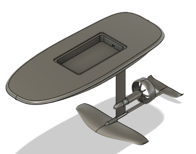
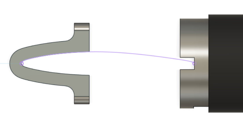
CAD snap-shoots:
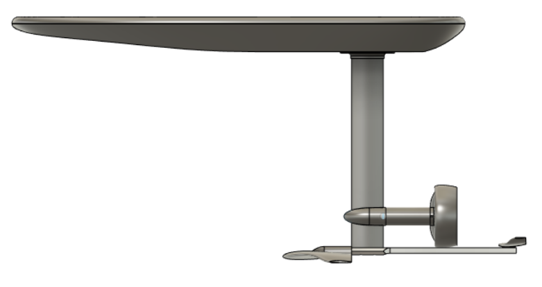
Side:
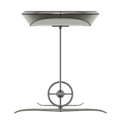
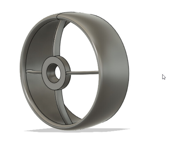
Front:
The Board:
165cm Long
96L
Hatch space: 57cmx29cmx7.5cm
Hatch lid: DPI marine Flush series 13x24"
https://www.dpimarineinc.com/flush_series
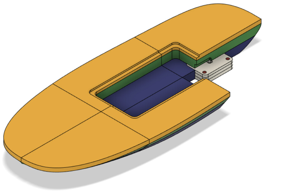
I will be carving the EPS foam core on my CNC router. Due to machine size and EPS foam availability in my area (Ontario, Can). I will use twelve 2x14x22" foam blocks and 6 1x14x22" blocks. 1lbs density. and glued together with EPS foam glue. I designed the board so that the draft angles of all the blocks will only require machining on one side.
Foil mount:
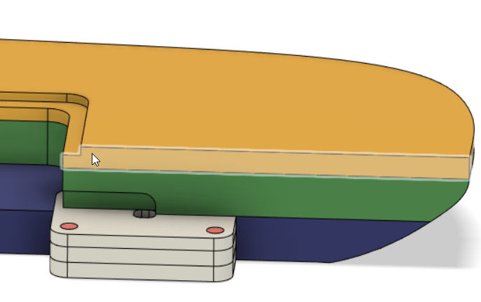
3 layers of plywood cut to fit into the foam core with aluminum rods that I can drill and tape for my foil mount. I will epoxy this into the foam and there will be a few layers of carbon between the 2" foam layers.
The whole board will be covered in carbon and glass.
Mast and Mast Plate:
Slingshot 71cm
Wings:
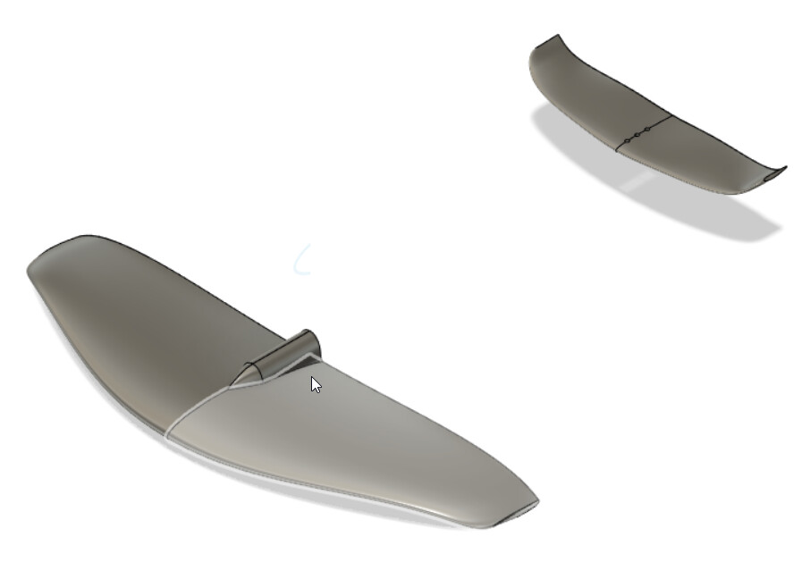
Front wing is about 1500cm^2 loosely based on the slingshot hoverglide wings. 80cm wide and 25cm long. NACA 2412 profile.
Rear wing 350cm^2 and 40cm wide.
These will be all carbon made in a close mold. Still working on the build process.
Electronics:
I debated long and hard about what to do here, there doesn’t seem to be many options. I decided to go with “HGL-Tech” motor, esc, and controller, because it is an all in one package, including propeller, and I have seen it be used successfully in other builds.
https://www.hgltech.com/collections/efoil-products/products/electric-hydrofoil-kits-65162-motor-7inch-propeller-300a-esc-wh4-remote-controller?variant=32981039808589
For batteries I am using 3 4s cells set up in 12s. 18amp hours. Amazon.ca Something Went Wrong / Quelque chose s'est mal passé
I have them stored in a waterproof computer hardcase: 1075 HardBack Laptop Case | Pelican Official Store
Fuselage:
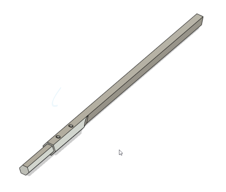
Carved from a piece of 1" aluminum hex rod. Length undecided at the moment.
Motor Mount:
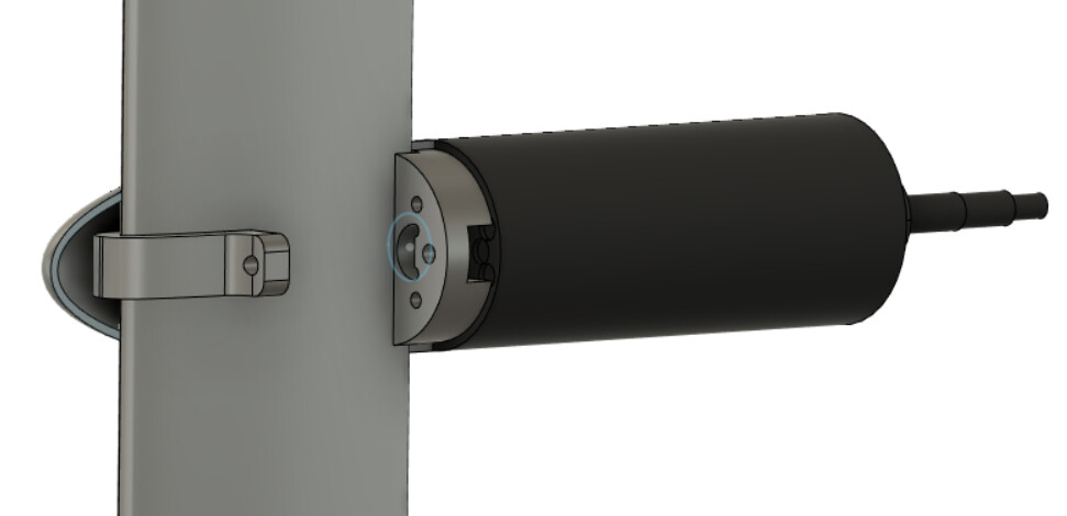

I will be using 19mm HPDE plastic as a mounting plate for the motor, and clamped to the mast with bolts through an HPDE Piece fit to the mast.
The fairings will be made out of carbon
Duct:
I am moderately worried about getting my toes cut off by the prop, so this duct is mostly for safety. I do not have the fluids experience to design a thrust increasing duct, this one will only serve to create drag, but may save my toes.
Right now the plan is to 3D print it from nylon Carbon filament, then skin it in carbon until it is strong enough. Will require lots of sanding and fairing but I think will be the easiest way to build it.
I have future plans for a folding prop, water-cooling, and a brain to motor the systems and throttle response curve. But these will not be included in the Mark 1 version
The build starts next weekend with the board. It is a few hours of machining for all the foam blocks, then they will be glued together and skinned in several coats. I will respond to this post with photos of the build process. I look forward to hearing your feedback.
-Z
 but typically when exceeding hull speed(that is very low on this length) a sharp shape might let go the water easier?
 , I’m in the middle of doing mine and my thumbs are sore and cracked from all the sanding.
 , would increase efficiency too.