Yes, I agree. It must have to do with the propeller as you say. The FR propeller is very inefficient and low speeds (“boating mode”) and very efficient at high speeds. I wonder if we have the parameters that were used in designing the prop? Target speed / rpm / thrust etc…
Your speed varies in a 600-1400 Watts range that is 1000 +/- 40% at a fixed 2700rpm. Interesting.
1 Like
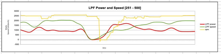
Speed displayed is x100 !
So I applied a low pass filter on the speed and power data. The time curves are much smoother
an example:
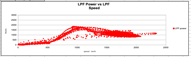
The power vs. speed looks like this:
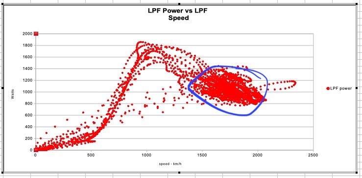
If you increase the Y scale, you get this below, which clearly (lol) highlights various modes of operation of the eFoil. The area circled in blue corresponds to the Foil Zone…
Actually I think we’re on to something as far as analysis in concerned. Filtering will be quite useful. The corresponding unfiltered data looks like this:

I’d be glad to test any propellers that are sent my way…
Yes, there is a huge amount of variation! I am still learning to ride, so I am making a lot of little corrections on my foot pressure all the time
How noisy is your setup?
I need some suggestions to make mine quieter. I printed this rubber pad to put between the board and baseplate of the mast. Any other suggestions?

Very quiet, no damping pad needed. Is your controller running FOC?
No… My husband designed and built the ESC and for some reason, we cannot run FOC. Is FOC known to be quieter?
Also, my board is very thick (GONG Mint). I’m wondering if it’s not acting as a sounding board?
Very quiet as your motor receives sine waves:
Some FOC ESCs are quieter than others… FreeFLY ARC200 (discontinued since sept. 2019) was quieter than VESC in FOC mode quieter than APD200F3 according to @Jezza.
Signal processing helps as described here:
2 Likes
This explains your noise issues. I strongly recommend to take another look at FOC instead of damping pads, different board etc.
Generally 6-step capable motor controllers should be able to run FOC. Running FOC requires more processing power, but the power stage, current sampling and BEMF sampling should work with the same hardware resources.
Are you writing the controller code from scratch or following VESC / ST MCSDK / something else?
Are you sure about this in the general sense? FOC requires a better position sensing than 6-step afaik and that accuracy could drive a need for better hardware and a better hardware layout.
1 Like
FOC requires an estimate of the rotor angle, which can be had from an encoder or through back EMF. You are right that if the back EMF is noisy, the noise passes through to the output easier with FOC than with 6-step. However, it’s their own ESC, and I would expect that if an electrical engineer is capable of making an ESC, they would also be able to add reasonable filters if needed. The layout plays a part, but even bad layouts can often be made to work. My point was focused on microcontroller and board resources in general, FOC doesn’t require extra pins on the MCU or extra controllers and such on the PCB to work, unless their board is actually based on a ready made 6-step motor drive chip.
The reason why we cannot use FOC is that we don’t have a sensor on the motor. We drive two poles and we read the back emf on the third one to have an idea of the position.
Oops, I wrote the answer before reading jkoljo’s answer.
Code and design is from scratch. (we had PC board printed but otherwise everything else is homemade. Charlie is very proud of it)
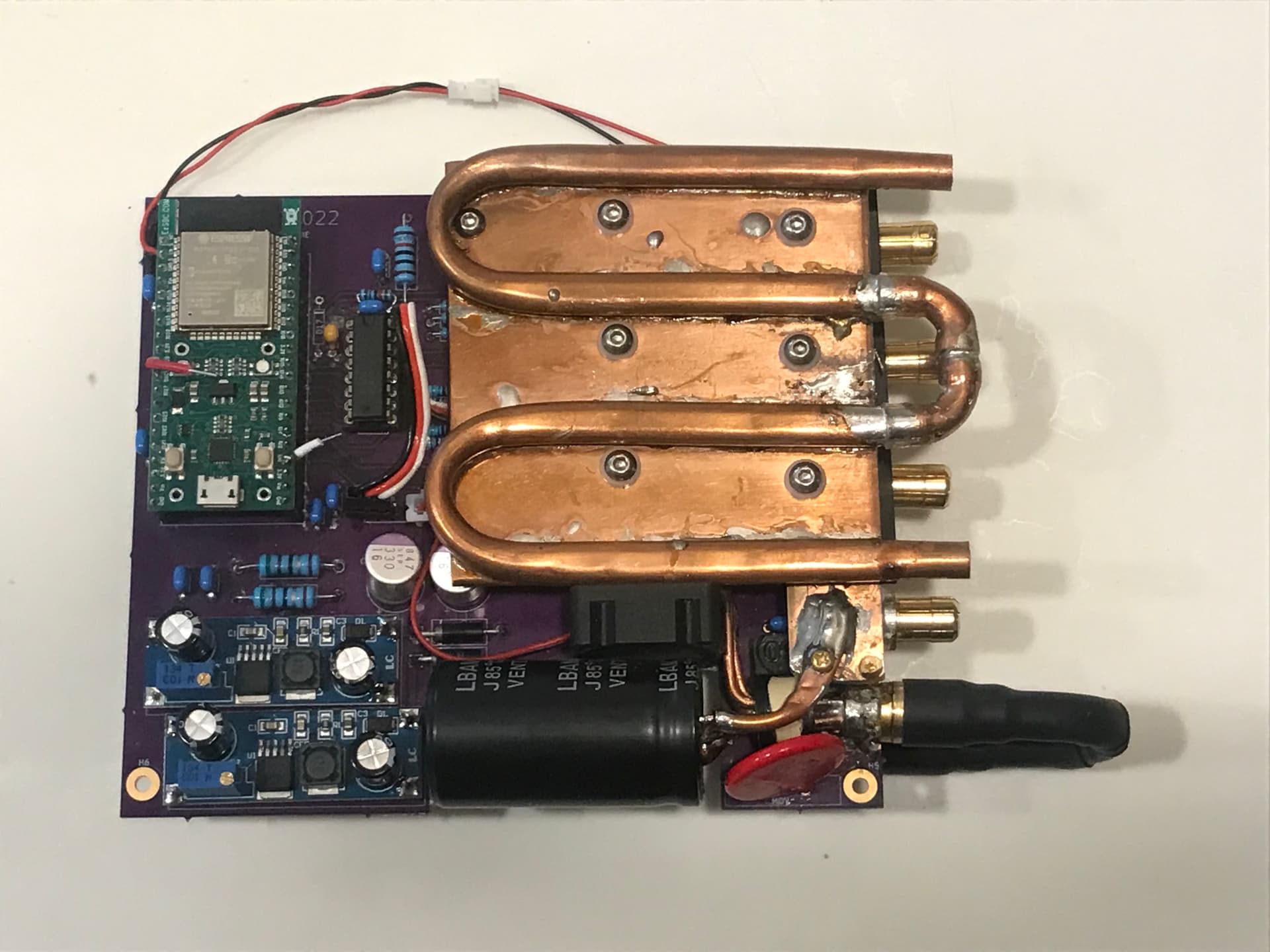
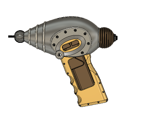
Yes, Charlie now has a new challenge! Reduce the noise of his ESC. In the meantime, I’ll keep working on my steampunk remote, to match the overall look of the project:
2 Likes
Hmm, I don’t really understand how you drive a 3-phase motor with just two phases. Can you share your schematic?
Anyway, modifying the design to run 3 phases + BEMF sensing on all half bridges will get you significantly smoother operation since it will enable not only proper 6-step but also FOC operation. 
Maybe also take a look at STM32G4 + some of their dev kits, such as the B-G431B-ESC1 or Nucleo G474 + IHM08M1. Their EVSPIN32 also has some nice things in it.
Yes, we’ll be glad to share the whole ESC design, hardware and software (but not support it…)
I meant we rotate the current between the pairs of phases, but in order to adjust the timing, we read the back emf on the phase that is not current-ly being driven.
Thanks for your suggestions, I’ll pass them to Charlie, as this is beyond my level of incompetence…
1 Like
Ah, that’s more understandable and sounds more like a basic BLDC (or 6-step) design. Since you have voltage sampling on each phase and you can drive all phases, there might be a chance to get FOC working as well. The code is much more complex unfortunately. And as discussed earlier, with FOC the back-EMF sensing needs to be clean since the 6-step function pretty much only cares about the which segment you are in, but for FOC the rotor angle in degrees also matters. ST and VESC motor control projects have examples on how to observe rotor angle from bemf. BTW for development purposes it’s easier to get started with an encoder if you have the spare inputs.

Does that qualify as very noisy? It sure is compared to the Fliteboard eFoil.
1 Like
Yeah, that’s extremely noisy 
2 Likes
I thought so… We’ll try some hardware and software modifications today.
I’m not sure on budget limitations, but an option may be to get a vesc and run it to compare against your own design. That way you have something to work towards/beat.
1 Like