Thank you, that is very useful information.
Well, I get too decide on everything… I think my board will be pink!  or red, since red is faster…
3 Likes
Nice video and nice work with the icebreaking!
That happy foil definitely looks like it wants to scoot.
1 Like
Impulse ans thruster, I have to, but no time for test
Greetings Frank
The orange foil with a low AR Front wing (546 x 225mm) and a thick mast released in 2015 ( continued in 2016) had different names during the development phase in 2014. It was then called "Happy foil’ or "Fun Foil’ to differentiate from the race foils from Europe.
Q3 2014, Liquid Force to offer a complete foil+board combo under 1500usd decided to recycle their heavy Kite Fish board (a bomb proof wake board). So the Foil fish combo was released and the first LF hydrofoil (with no official name) sold alone without board became the Foil Fish. People today still call this foil the Happy Foil or Fun Foil.
The first edition of the Rocket foil appeared in 2016. Coloured in anodized red, same plane as the foil fish (source of confusion) but faster than the orange Foil Fish due to a thin and long chord mast (13.5 x 124mm)
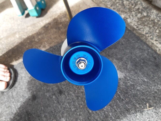
The name Happy Foil was not lost and was officially used in 2016 to name the anodized blue foil (continued until 2018). Fitted with the (new) same 13.5mm thin mast as the rocket foil, plus a higher AR F wing (615x155mm), ok for kiting but too small a surface for efoils.
1 Like
OK  thank yo for Info
Greetings Frank
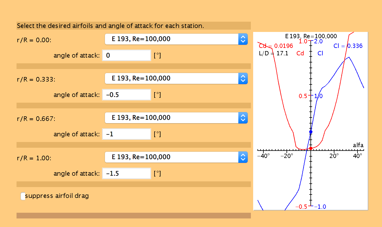
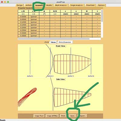
Next step, design the 6x6 propeller to my specifications, using JavaProp. Here are my design cards (I requested 222N of thrust instead of 111N that was computed using Dmitry’s FoilBoard application, just to be on the safe side).
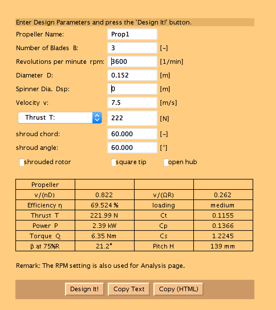
(don’t forget to set the medium to “water” instead of “air” in the option card).
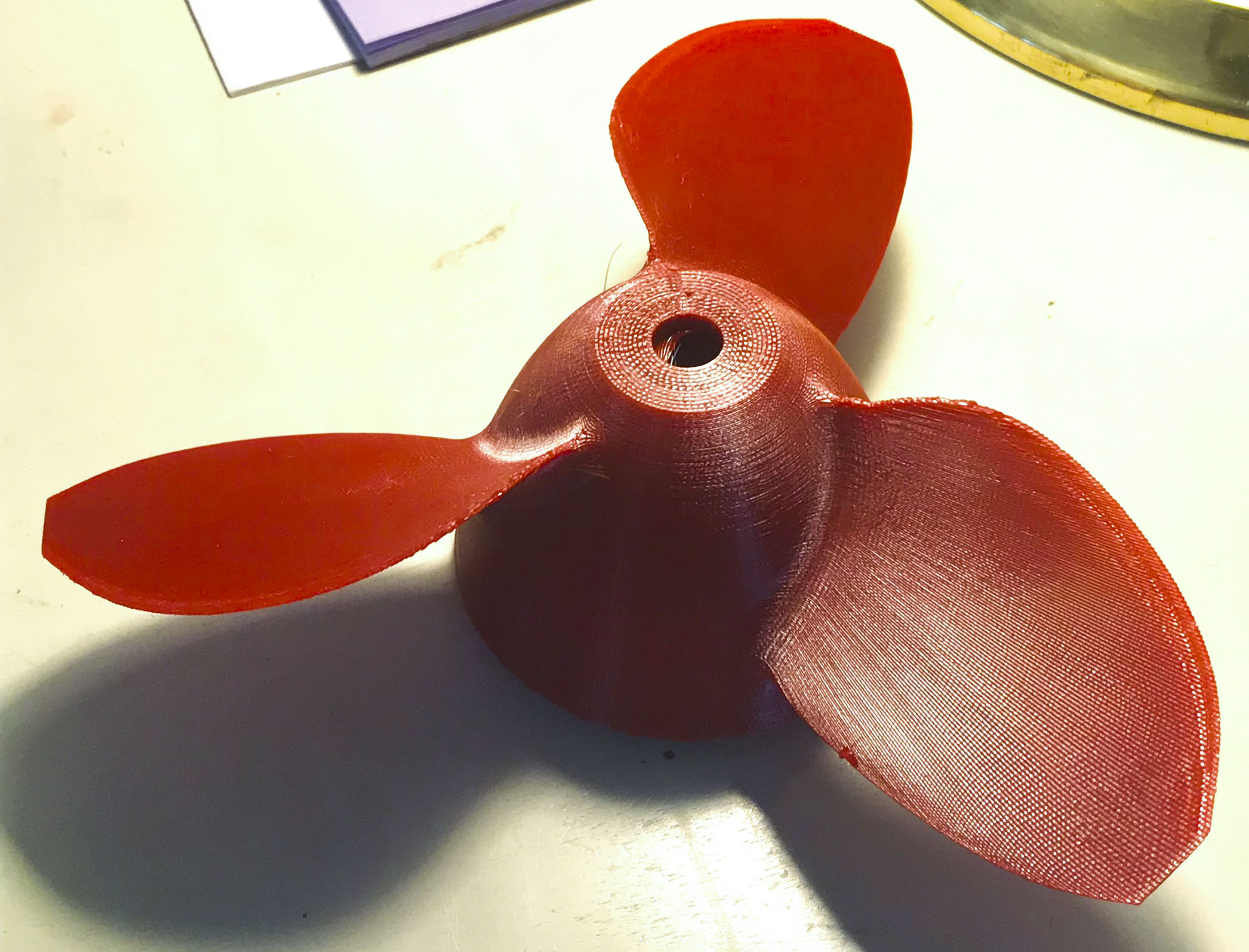
And, after importing into fusion 360 and adapting to my splined MTI65162 motor shaft, here’s what I got (notice the high speed red color):
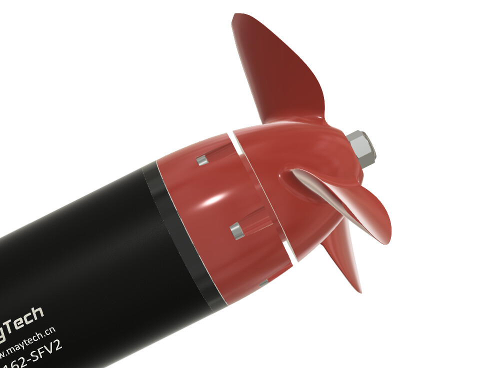
7 Likes
Looks very promising! Can’t wait to see your data!
1 Like
Can you share please the CAD from your propeller?
I want Test it in the summer 
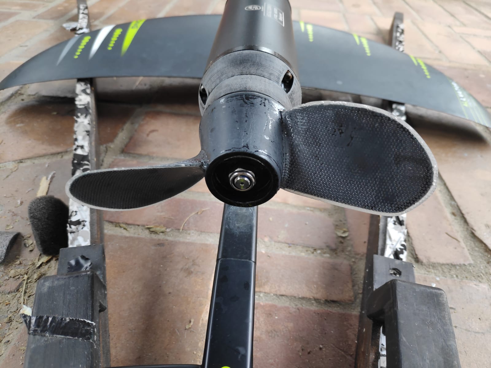
Interestingly, the most silent prop have a hollow termination, here FR who call it the “Ninja prop” for its discretion… This prop is fitted on a 6516x motor as yours. Credit to @michion
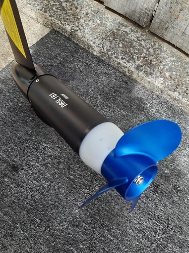
1 Like
But there are other tracks like the longest possible boss seen here so far:
How did you manage to import the data from Javaprop into your Fusion?
Typically the open termination is an exhaust outlet and not required (no exhaust). A tapered termination is much quieter and more efficient, less negative pressure at the termination. Take a lesson from a nuclear sub and what Electric Boat folks are using for silent running. (I worked for General Dynamics Electric boat Div. back in the seventies and used to walk by their prop setup daily).
Not being critical of your post at all, just wanted to provide solid info so we don’t try to reinvent the wheel (pun intended)
In JavaProp, after designing the prop, go to the Geometry card, press the “Save” button on the bottom row.
Select location and filename, add the .IGES extension (that’s how JavaProp knows what format to use).
In fusion 360, UPLOAD your .iges file (in the data panel on the left).
That will create a design in the data panel. When you open it, you get an unstitched surface that you need to make into a solid object by patching and stitching in the “surface” work space.
Sure. I will soon put a link to it. This is still totally experimental. The printed part looks fragile. I will, I hope, have better designs later.
Here: https://drive.google.com/open?id=1OXrzUhglrOrYG3eaNeCNGqHEfXEgSKto
PRINTING THE PROP
This guy’s channel here has a lot of information on how improve the strength of 3D printed parts. Following his advice, I printed my propeller in PETG, with the following setup:
- layer height 0.15 mm
- line width 0.56 (140% of nozzle width)
- perimeters, top and bottom layers: 6
- infill 50%, full honeycomb
It printed nicely, but looks fragile. I will try to improve the design, but at the same time, I’m looking at ways to reinforce the part after it’s printed.
How propeller works in reality compared to theory is always a very interesting topic. In the small outboard segment, let say 6hp, You see propellers with both exhaust through propeller and other versions without, having the tapered termination. Still in performance no significant difference either way. As far as have seen, FR is considered one of the best props still having the “wrong” design. Actually it looks a bit like a cut mercury 5-6 hp but with cut diameter. A pity its a LH drive prop, would be fun to test it on a outboard and compare. The more tapered style Yamaha clone prop has as a dimeter cut version been tested here by a few, but believe the FR prop is still so far the best working design.
In higher speeds the hollow “tube” is also adding some lift, this feature is probably less on tapered version.
Another interesting thing is that in theory, a Rise speed nozzle should increase efficiency compared to propeller only in speed up to 18 knots according to some studies on larger vessels, but think in our application the practical result has been the opposite.
1 Like
Also, we need a complete new design optimization for “small 3D printed propellers”.
You can put GFK / CFK pieces on the blades (front and back) to enhance the strength. My only printed props broke quite fast; the new ones are still ok.
3 Likes
Not going by theory but actual testing. I would take some video with my gopro but the drag from the camera might alter the results. Most people are static testing, which only gives you a close estimate of the foot pounds of pressure your dealing with. You can check for pressure differences using different prop configurations but you might not be able to check cavitation with a static setup. Moving through the water at full power is quite different. Keep in mind we are dealing with fractional horsepower at high RPM and an outboard at multiple horsepower at a much lower RPM by as much as 20X . so in the outboard you wouldn’t notice much difference…
It was mentioned in this thread that the open ended prop was quieter than his original setup. It may have been an unbalanced prop in his original setup and the new prop is more precisely balanced and therefore quieter…
For your left hand drive prop run you outboard in reverse gear (a lot of small outboards have the same gearing for forward and reverse)…
The hollow termination only adds drag and no lift at all and adds to cavitation. air and water mixed together equal less bouyancy for your craft to stay afloat and less available power when it happens at the prop.
I agree on the nozzle, there is quite a bit of extra wetted surface and aside from protecting your feet and legs from the prop they reduce efficiency up to 10% depending on the design. I printed one but don’t plan on using it or testing with it on the motor.
1 Like