Coming to the first test run.
The board overall worked fine.
A bit of rework is needed, because the controll unit gets quite hot. I hope I can do something in the settings to reduce it.
Those 3 wire inlets into the box are not perfekt waterproof. small drops came inside.
Does anybody has a better Idea how to make the inlets waterproof, but still easy to disassemble.
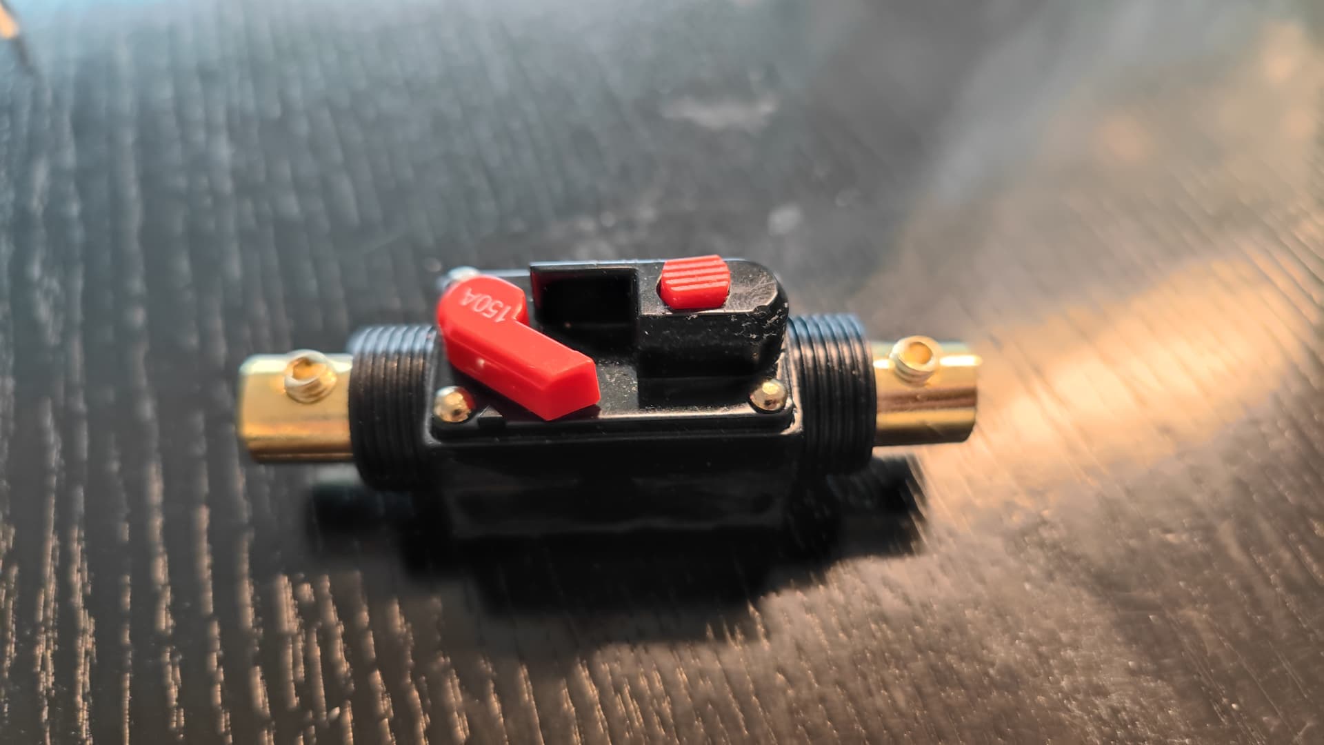
The last thing is that the cheap china fuse can by far not withstand what is written on it (150A). Something in the inside melted and now it is not possible to trigger or close the fuse anymore. Is that issue know or did I just could have a faulty part? Anybody also using that part or another better one?
Who wants to see what such a cheap efoil can do, see below.
I will improove the issues and then making a calculation, what it was overall. I assume it was more like 700€ but the battery is quite big.
People used those in the early days 2019/20 but most cheap ones could not withstand more than 60A, no matter what they were rated.
Better use an antispark connector like xt90s or QS8S. If you want a fuse, midiOtto 150 - 200A is rated for 58V and is quite compact. Works well in my 2 boards.
Here an update. I opened the fuse and the metal pins which are making the conection inside are held by cheap plastic which melted down. I excluded the fuse and did a second testrun:
(proper foiling skills ;))
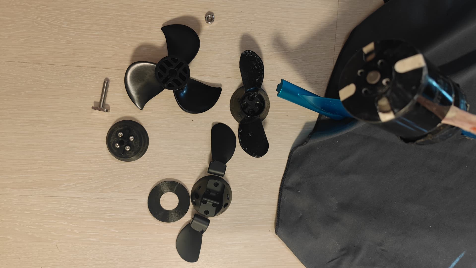
Unfortunately the the ESC got to hot and is shutting down. I got a hint that maybe my prop does not have good efficiency. It is the prooven Volkers prop, but I printed with a bad printer and I deformed the prop maybe also a bit due to heat (I wanted to eliminate burrs at the edges and flamed it. The prop got very soft while that) and I also fixed an edge with UV-epoxy (I crashed the prop inside my door :D).
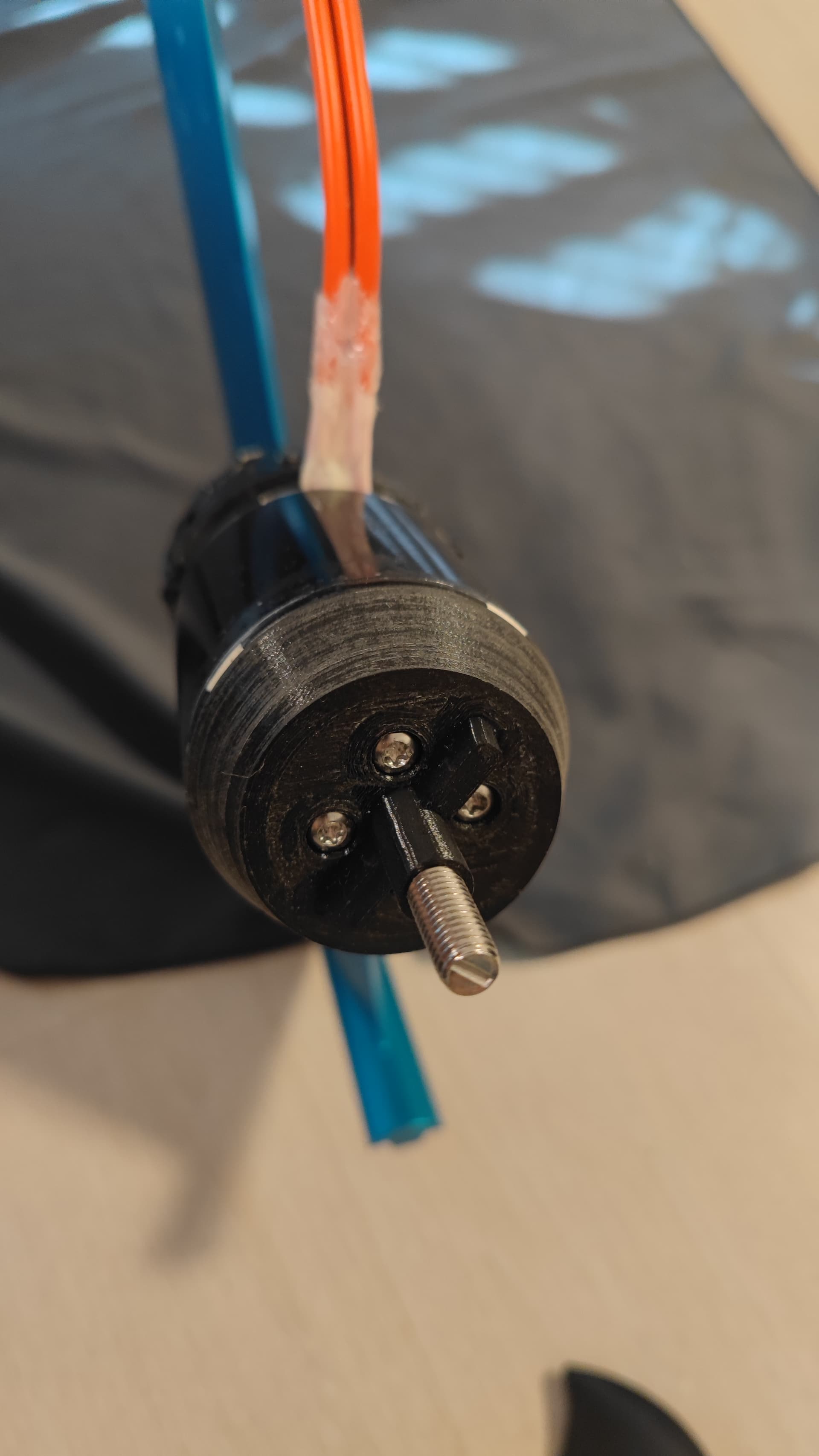
So I have bought a plastic flite prop and a 38€ flipsky aluminium folding prop (https://a.aliexpress.com/_ExFvH3u) and printed mounts for it:
I also bought a cheap china wifi amp/power meter and built it in the board to compare the new props (conection to smartphone works fine): https://a.aliexpress.com/_EzZ7fiA
The fuse I exchanged to 175A also from Ali: https://a.aliexpress.com/_EIVDPfu
So on the weekend I will test at least the flite prop. So let us see how it is going out.
that adapter for the flipsky folding prop is from @seagull_nz (BDUAV 120kv Motor Flipsky Prop Void Fill by seagullnz - Thingiverse). I could not find his original post, so I hope it is also fine referencing him like that. The fit on my 6384 is excellent (perfectly centering and in line with the outer diameter). It fits also to the flipsky prop which I got, anyhow the outer diameter transition and centering the prop could get even more improved (maybe Seagulls prop has slightly other dimensions).
I ordered this 38€ alu folding prop: https://a.aliexpress.com/_ExFvH3u
The flite adapter I did myself. Centering on Motor is quite good (not as good as seagulls for the flipsky. He has here really 0 play). Centering on the Fliteprop side is perfect for mine, because I optimized for that. But it could be, that it does not fit to others, because there is also a flite prop measurement of someone else in the forum and that is deviating for several 0.x mm (3 blade prop file? - #3 by SoEFoil). So looks like there is quite a lot of fluctuation in the part.
Here is all of my data(creo, stl). I printed it with the motor side upwards to have a really smooth surface on the motorside to fit better to the motor. https://www.dropbox.com/scl/fi/wgwijfsukrtipn820o3ka/Fliteboard.rar?rlkey=u11s3kgsfxi8x5u8ni76h43tk&st=2idw0cxx&dl=0
Screw which I used is in M8 x 40mm: https://a.aliexpress.com/_EzxgdmW
For the flite adapter attaching to the motor, I use quite short screws (10mm) to keep everything compact)
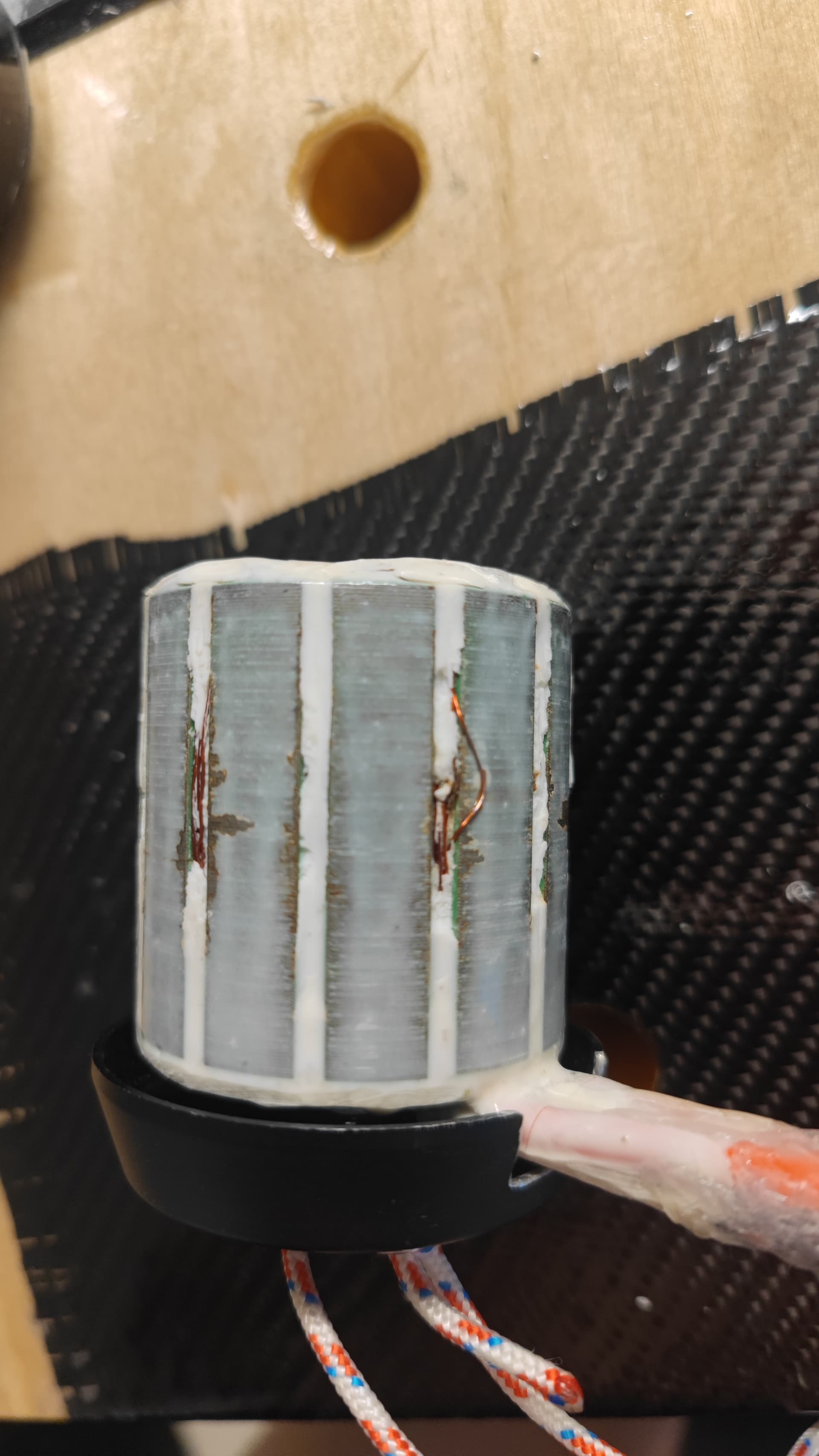
I tried today the flite prop. Seemed to be much better to me. Had more power at lower throttle. Current I do not know in detail because I do not have measurements from the self made prop. But now coming to the issue. After 400 meter of driving I got a complete shut down and motor started stuttering. I opened the motor and unfortunatelysome epoxy got lost and the wires got pressed out. that is strange to me why the wiring moved out between the rotor and stator. Does anybody have an idea?
I ordered now a new one (unfortunately a sensored one, but this was the only one I could find here in germany on ebay to get it fast. This time I will do it with corrosionX for eliminating corrosion inside. Let us see how this works.
Is it possible to remove the sensor easily or will I get issues with that?
The same thing happened to my 6384 flipsky motor. I have two options: the epoxy layer is breaking down due to vibrations from bad bearings or poor propeller balancing, or it is heating up and breaking down because this type of resin is not thermoplastic.
No, I did not prepare the motor. Also to my mahnets onn the outer rotor it is not sticking. So I removed it from the magnets with a screw driver. Now there it is just between the magnets. I put grease on the magnets. Let us see if this works. Next time for sure I will not don it myself and will pay double the amount for the flipsky
With the new motor I did the same coating again, because corrosionX did not arrive before I had to leave to lake garda. Unfortunately the same issue happened once again. But this time I kept the circlip off, that I can pull off the rotor. So I analyzed the motor immediately after first signs of same issue occured. This time epoxy was not removed but it smelled burned. So I assume my coating does not conduct heat enough. It also looks like that it burned at the end surface facing towards the propeller. So next motor I will for sure not do on my own. 3 options which I am thinking about right now.
-flipsky 6384 and using it with short cooldowns between starts
-flipsky65161/maytech65162 to get some more power. (starting against wind waves I was not capable of, only going with the wind waves)
-65220 with integrated esc (I am feared that I get overheating problems with my esc which is right now just placed in the batterybox without any active/passive cooling).
What are your thoughts/opinions on that?
I have a Flipsky 6374 which is working great so far.
Compared to your picture above, there is barely any coating on the stator.
The gaps with the wires are actually recessed, so they are not flush with the stator.
I assume your coat is way to thick, probably due to the white stuff mixed in.
Above you see visible rubbing marks.
Your epoxy is probably rubbing against the magnets and thereby creating the heat you are talking about. At least that is my guess.
On your motor I would try to sand away as much of the coating as you can and then try again.
Thanks for your comments. Helps a lot for reflecting. With the thickness I had indead issues with the second motor in the beginning (there is grease on the outer rotor, so it gets black where it got in contact). The first one was thinner. On the second I grinded down the contact points and thereafter, there were no contact points (also not under load). Overheat of the motor happened after grinding. Due to the fact, that I do not want to loose more time on the water, I am giving up with the selfbuilt of the motor.
After some more thoughts on the burned motors, I think the option with the aluminium did not work. The thermal cunductivity I assume is to low. Bubbles in my epoxy did not improve the situation.
I dont know if someone else tried already the aluminium, but for me it is not working. I bought now the flipsky 65220 with inside esc in 120kv, uart mode and threaded shaft. Hope this will go better.
Hi everybody, the 65220 (75100 vesc + 65161 120kv motor) is instaled and this time I also designed a proper hydrodynamic cone for it (will upload everything). Unfortunately while the first testrun on mirror flat water today, I got to less thrust (12s fully loaded) to come out of the water. I used a fliteprop and vesc is limited to 95A phase current. The vx3 transmitter (uart) is showing only 43A while the testrun.
Right now I am a bit lost.
Does anybody has an idea what the reason could be or how I can find out the rootcause?
Is the fliteprop maybe known to produce to less thrust at 120kv 12s? Otherwise I can only imagine that somehow the rpm is limited in the vesc. But I could not find anything in vesc tool.
Can‘t be the prop, I use a flite prop on a 63100 outrunner (135KV). It has plenty of power on 12S. I can get up to 110A battery current and 160A phase current. I suggest you increase phase current to 120A and abs max between 150 and 180A. Make sure to also set battery current to 2/3 o f phase current → 80A. Also make sure your battery can deliver enough current.
There are numerous posts and comments with Flipsky ESCs not being consistent with VESC Tool settings. My first experience with a 75200 can only be described as traumatic.
Based on some other comments and my experiences, sometimes you need to enter some values and write them to the ESC, even if they look good. ERPM has been one of them for me.
What you could do is save the motor config to the config file, then upload it to ChatGpt to get an opinion, or go through the individual settings and get ChatGpt recommendations. Someone was having problems here and shared their config file and I uploaded it ChatGpt, and it wasn’t happy at all listing all sorts of problems.
I used ChatGpt and it went smoothly for my 75100 setup, however when I uploaded logging files to ChatGpt and DeepSeek, they both replied it was just ESC idle. DeepSeek is usually only good for one question before it is too busy, and ChatGpt gave some rubbish about another file it was comparing.
I was disappointed on the logging file analysis, but probably expected too much, but still really good for setup.