I have unfortunately had three Flipsky 75100 Pro V2.0 fail. I have potted each Vesc and have had no water ingress whatsoever either into the box holding the Vesc or the Vesc itself.
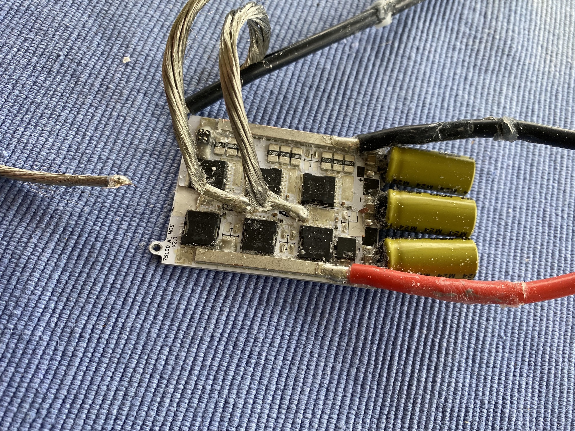
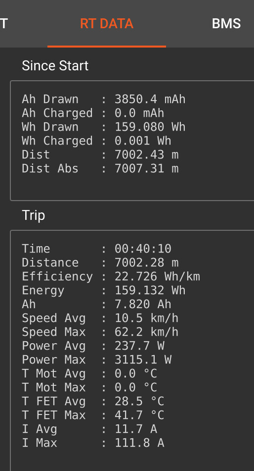
I can’t remember the exact issue with the first failure as it was in June. But the latest two I have a reasonable amount of info. The second one ran faultlessly for about a month then started cutting out giving cogging style of issues I spent many weeks trying to replicate the issue consistently but it was intermittent and very hard to analyse. After checking all my RTData on Vesctool there were no significant amp readings or temp readings. Max amps around 110 with 20-30 being normal from remote when cruising around. Temps maxed out at 52 on one session but normally maxed out at 47. Eventually the Vesc stopped turning the motor altogether and so it had to go. Now that I have had my third failure I decided to pull that second Vesc apart to see if there were any telltale signs of deterioration and the only thing that showed up was when I started pulling on the cable to check the solders and their connectedness the first one pulled off the board very easily. See picture. Is this what other are mentioning as checking for bad solders or is this something else? I can’t see how this could be fixed other than a big improvement in the building of the Vesc and that attachment at creation by Flipsky.
The third failure was quite different. Everything was working perfectly for about 6 weeks. Then out of nowhere the system just started cutting out about 30 minutes into a session. I would sit around for a minute or two and then it would work again for about 10 minutes and then cut out again. There was no consistency or what I was doing when this happened. I could be cruising around, it would cut out. I could be coming off a wave and pull the trigger and nothing would work. I could cruise in and dropped into the water to talk to a mate and then not be able to get the prop to spin with even the slightest trigger pull. Again no high temps 52 max, amps max of 111.
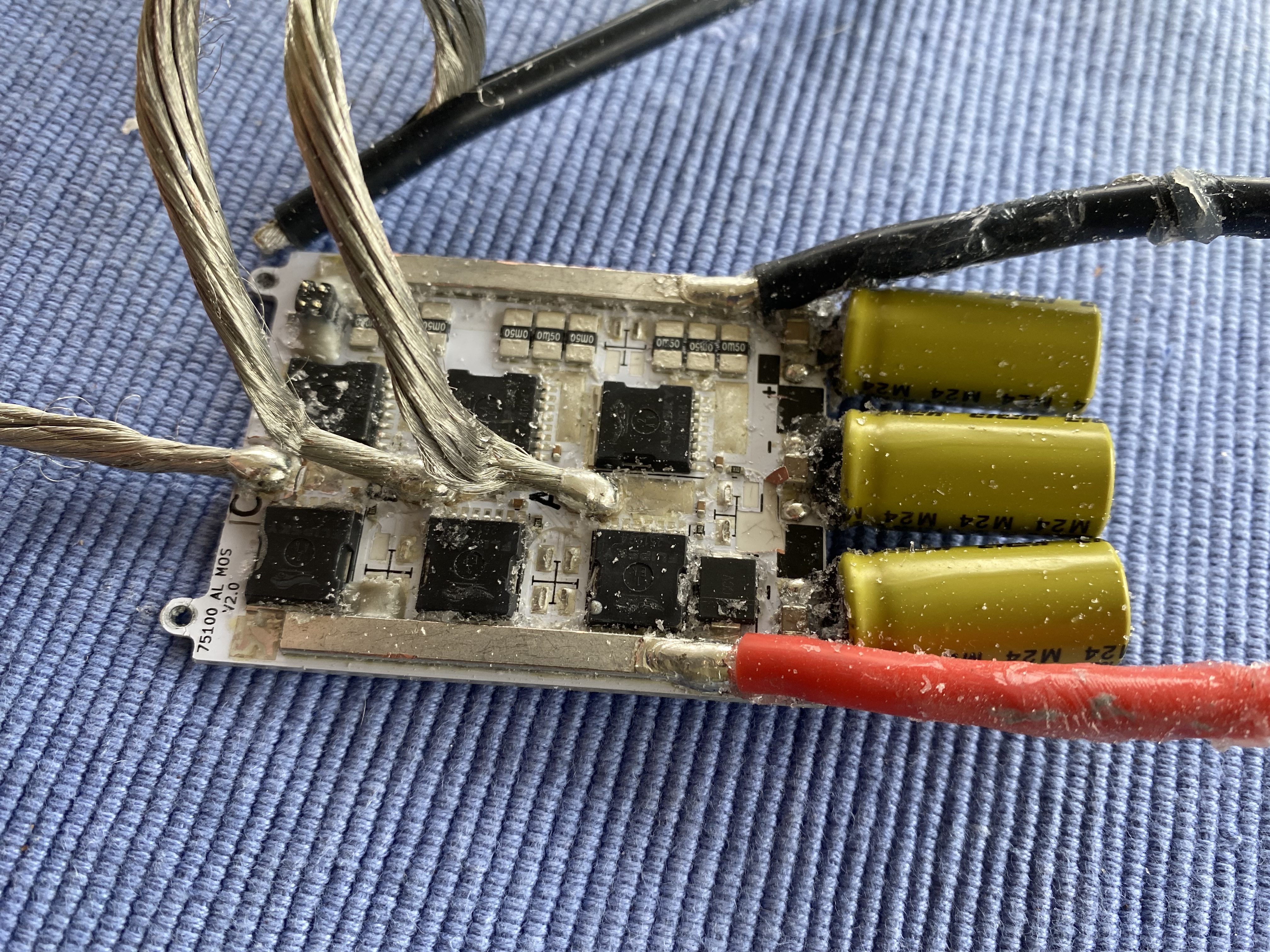
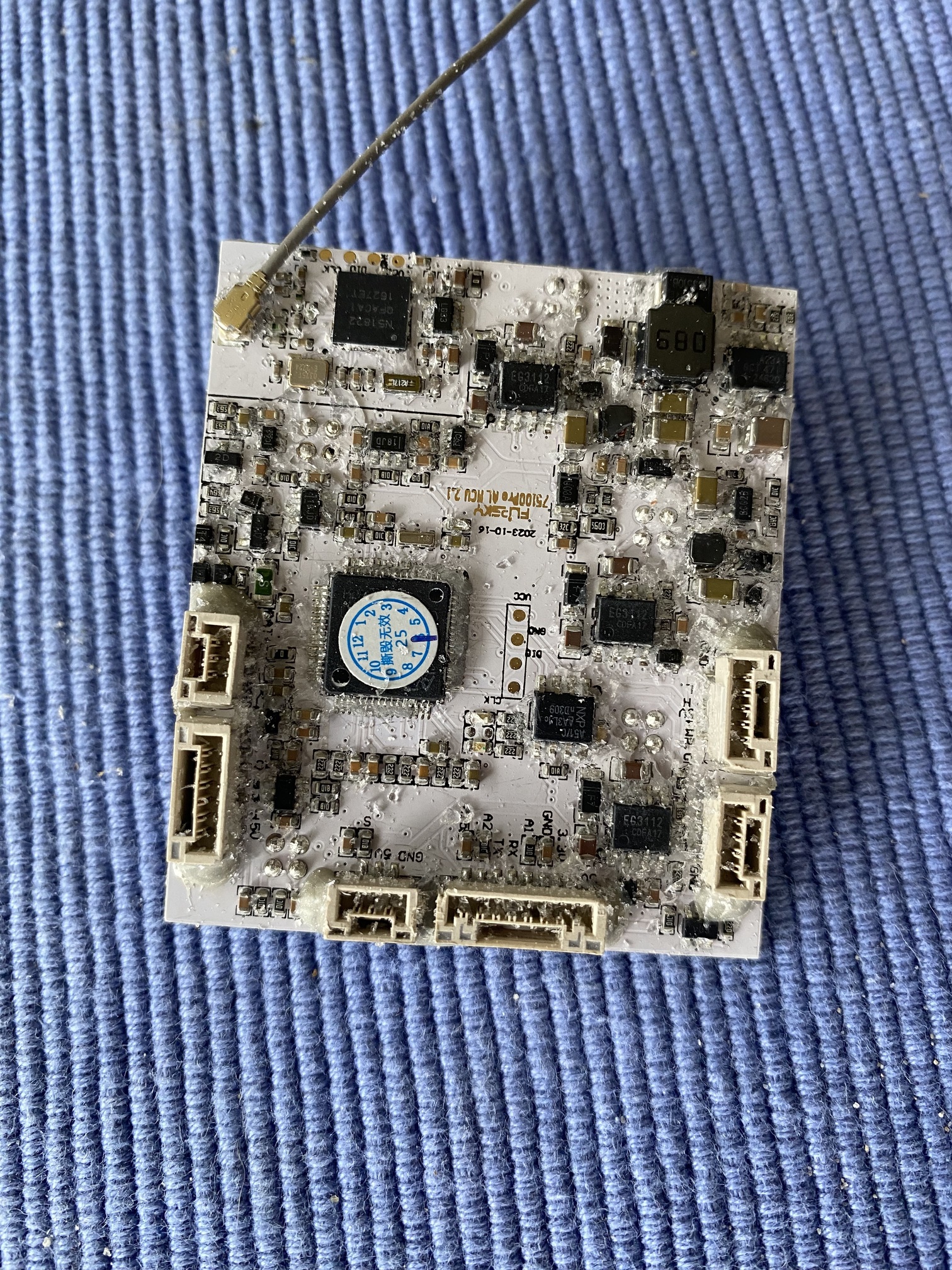
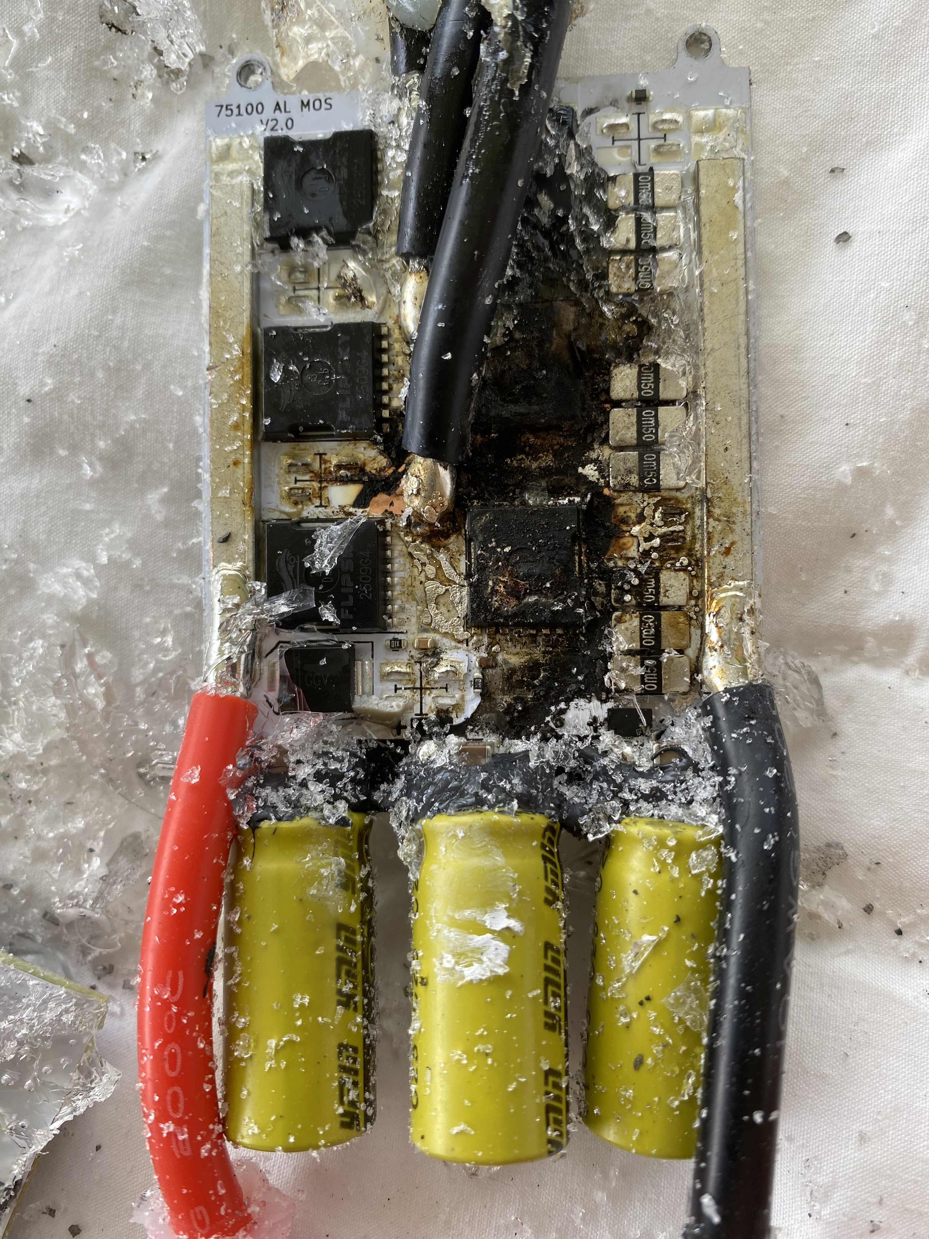
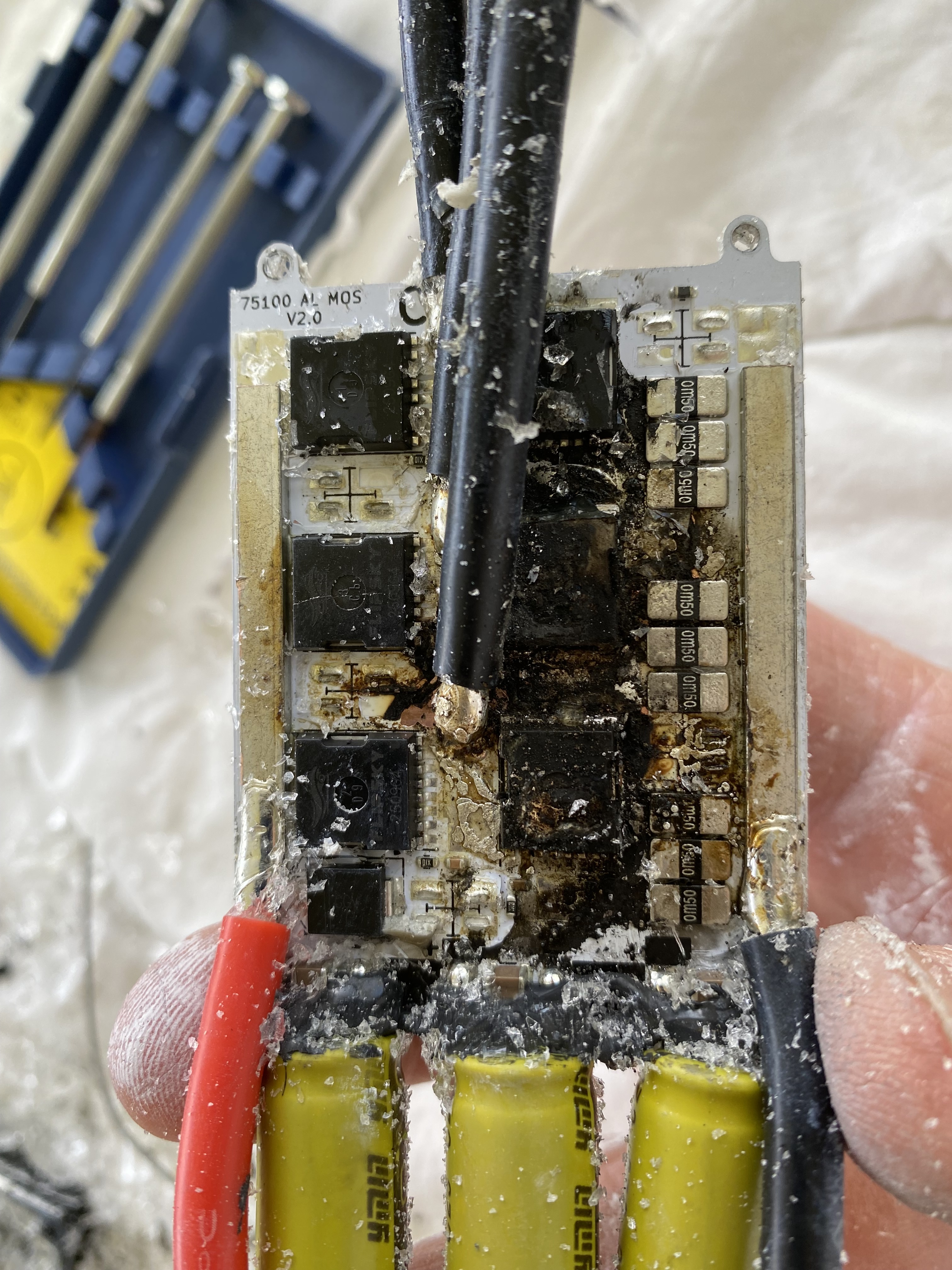
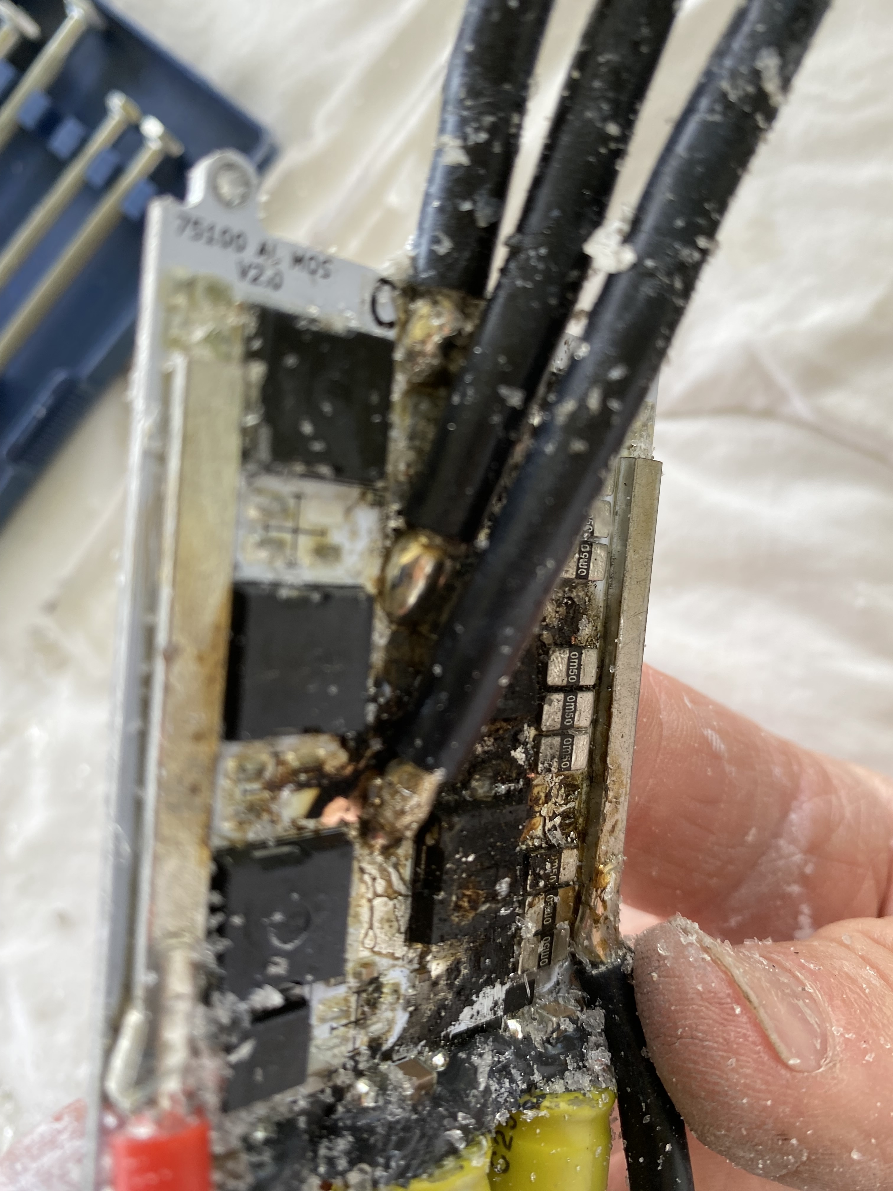
Eventually and I was extremely lucky that this happened onshore with the battery cover off the Vesc basically caught fire whilst attached to the battery. Luckily I was able to disconnect the battery and get it away from the Vesc and I have a feeling if it the Vesc want potted I could have been in a little bit more trouble than that. Pretty sure an 11S3P fire would have been a bit sketchy.
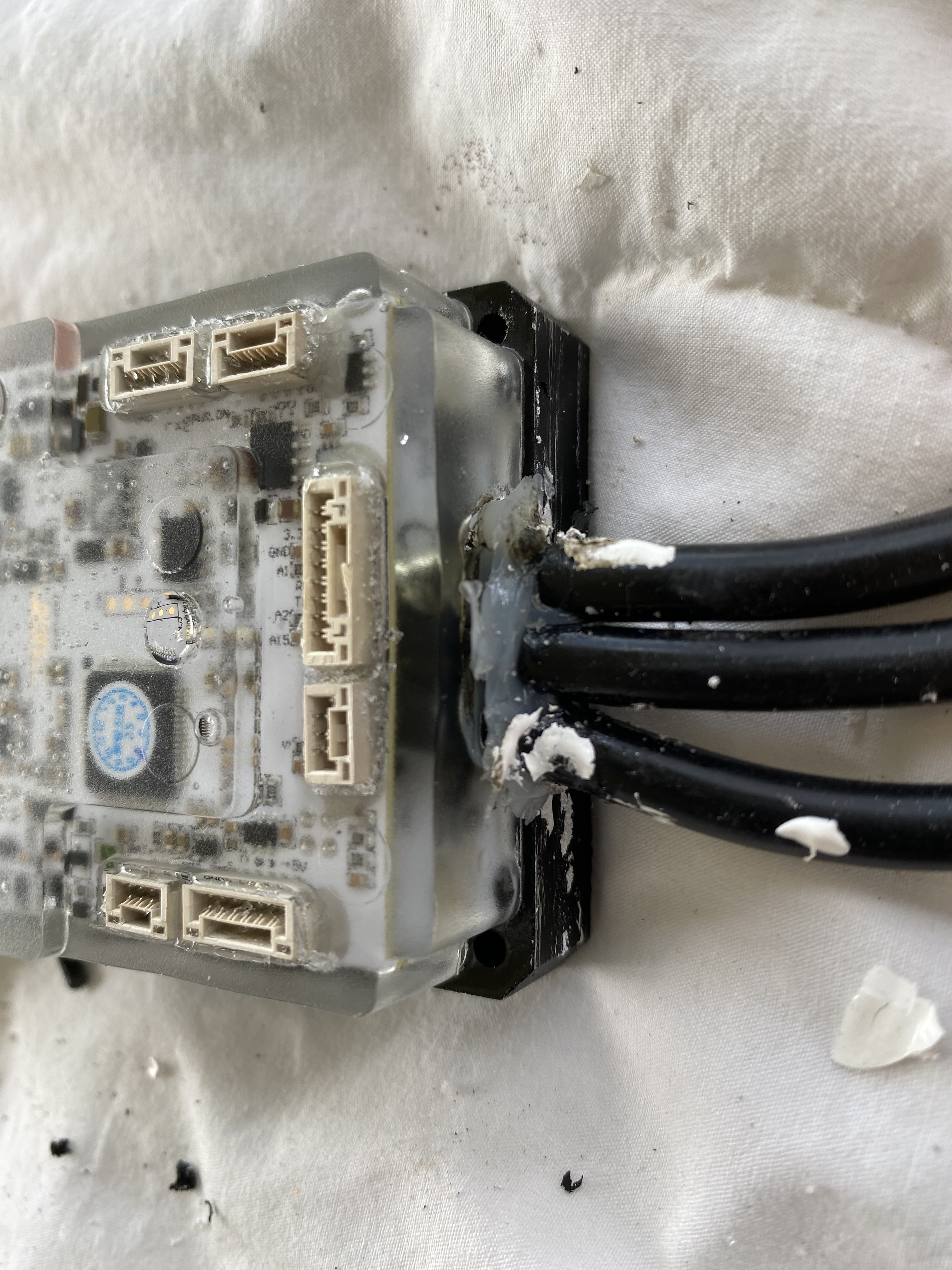
I pulled the Vesc apart and this is the result. See pics.
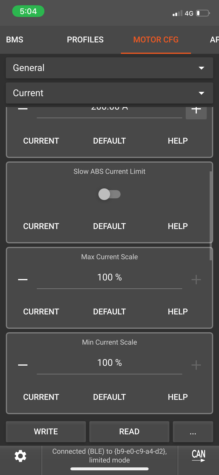
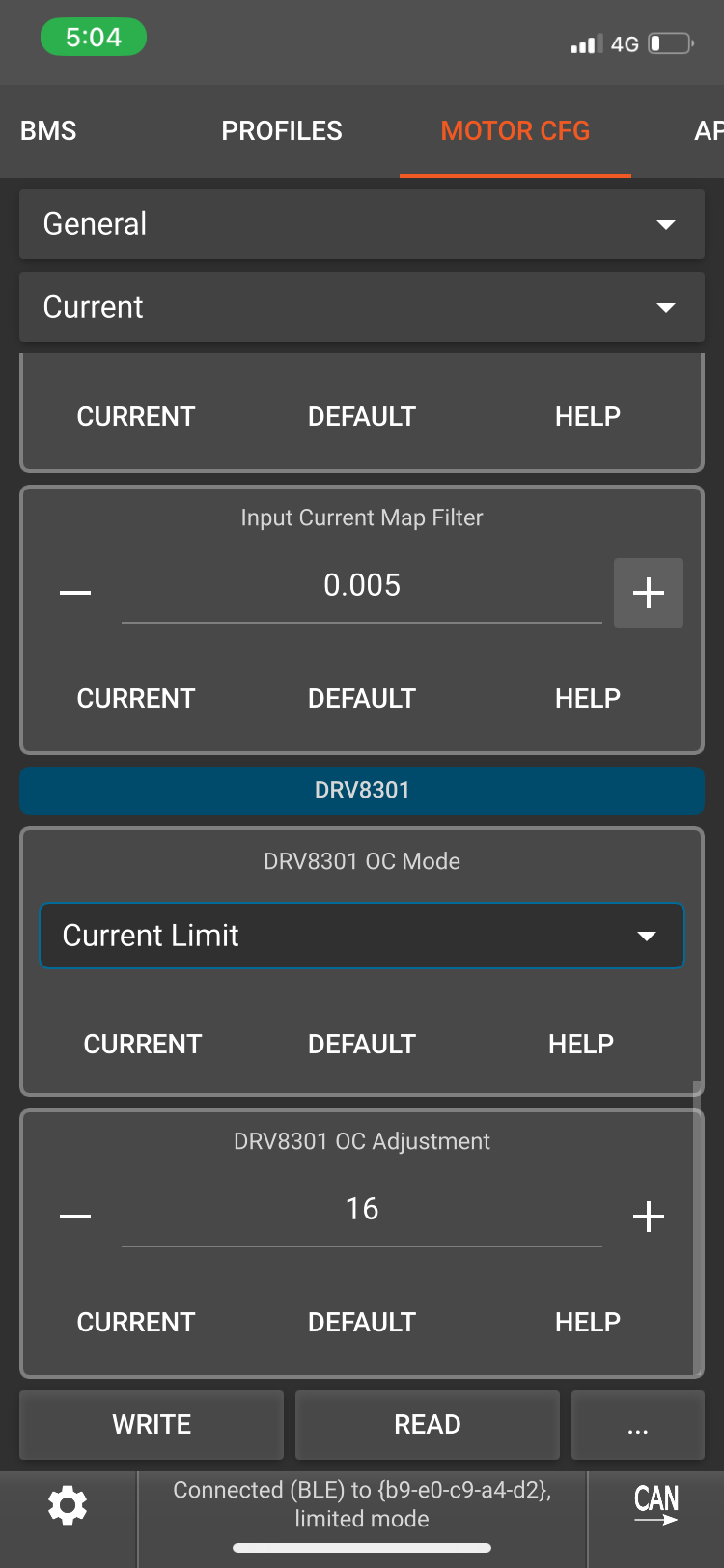
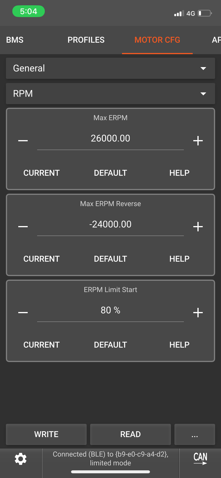
I have followed Ludwig’s setup video and feel that I am not stressing the Vesc with my temp and amps so is there anything else I can try in the Vesc tool to try and prevent these issues or is the Vesc really just not up to the task?
Any help would be appreciated.
Motor and battery setup below.
How was the bottom PCB with the FETs attached to a heatsink? Was there a good, even coat of thermal paste?
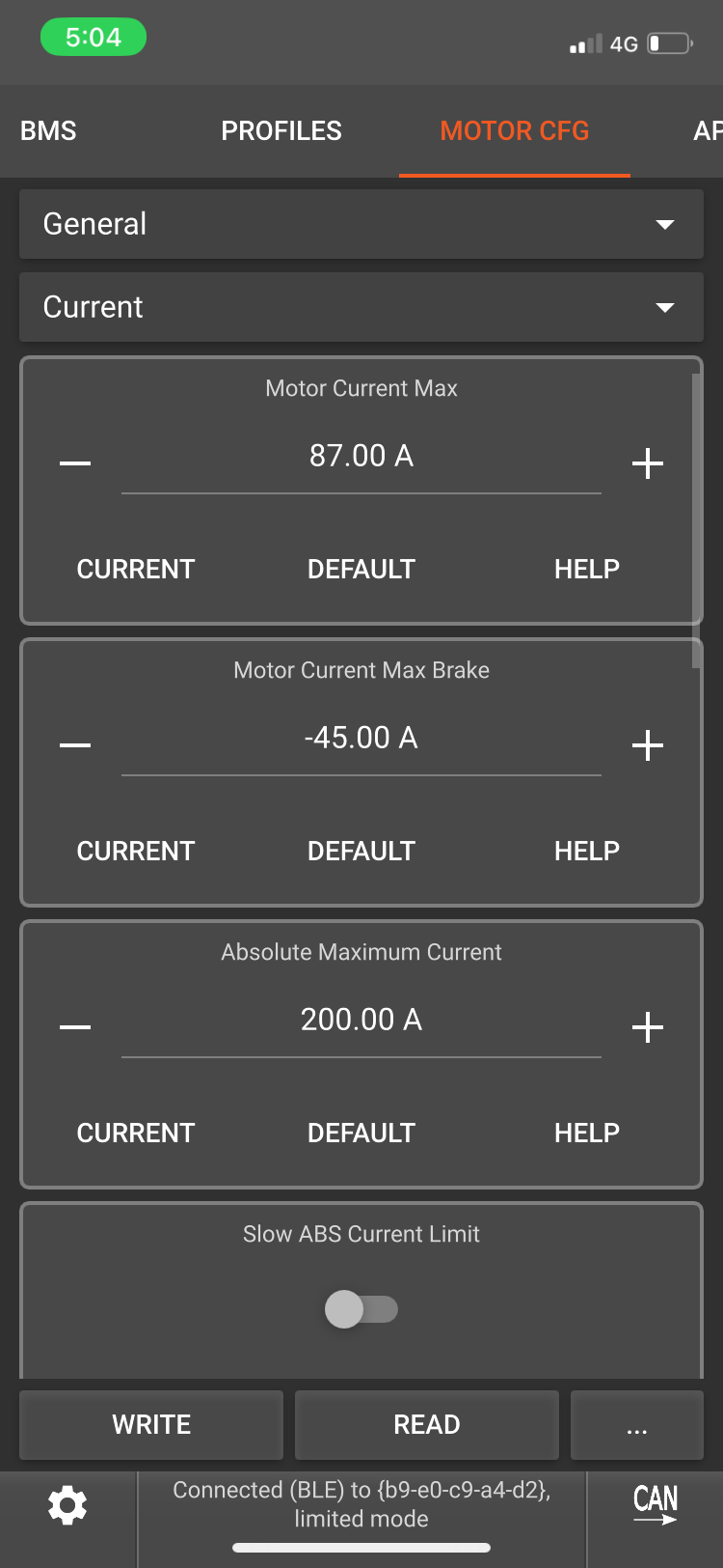
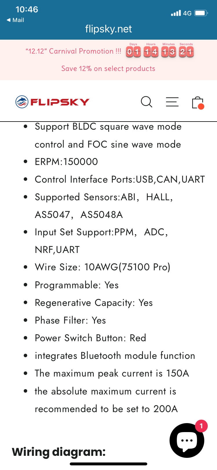
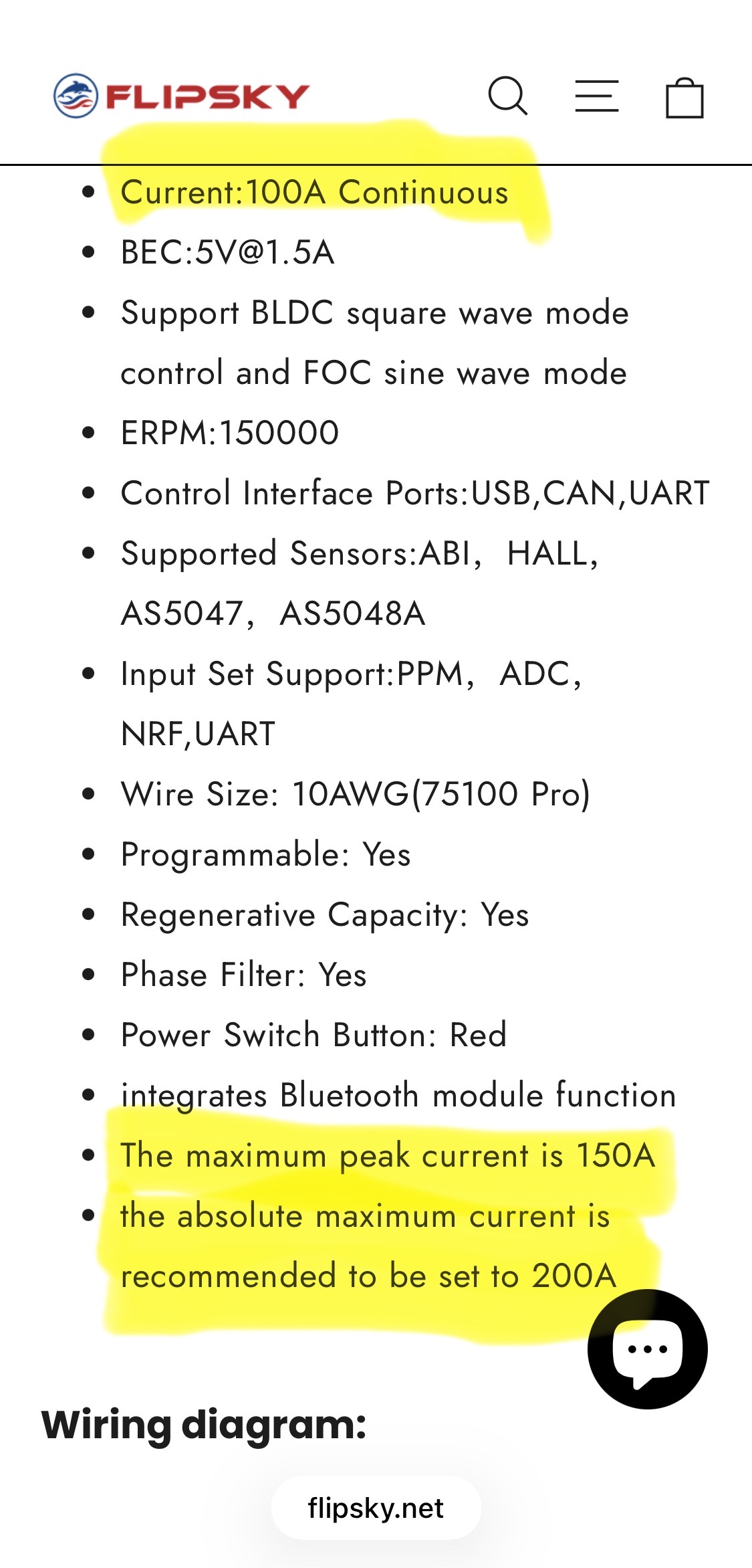
Well, with your measured 110A amps, you are over the limits specified by the manufacturer (100A) which I would generally stay away from for the “cheaper” VESCs. Setting absolute max current to 200A on a 100A controller is kind of begging for blown up FETs…
Also temperature measurement is in one place on the FET PCB, with the above described problem that sometimes thermal paste is uneven, other FETs can have substantially higher temperatures
If this happened all with the same motor, check that no screw is damaging the phase wires and that no other (intermittent) short circuits are possible. In the future stay at or below 100A for the maximum value, or get the 200A VESC
I have swapped motors back and forth and have been getting same cutouts.
I assumed that the max amps of 110 would have been a very quick spike and not for any significant time. As per the Flipsky recommendations for this Vesc that is why the 200 abs max. And as I said motor current max is set to 87 which seems far below the 150 Flipsky states possible.
I did notice as I took the last Vesc apart that the paste was not covering the gap evenly so I’ll investigate that further and see if my current 75100 is the same and make it even if it’s not.
Thanks for your input. Feel free to correct me if I have stuffed something up.
Good point, on the other hand the “waterproof” versions of flipsky 75200 and similar VESCs seem to have the same hardware, just potted by flipsky themselves… so they themselves seem to be fine with potting and hindering airflow… also the power draw and therefore heat dissipation of a 75200 is quite low (I remember 10mA @ 80V = 0,8W)
Best solution may be to use a thermally conductive potting compound… but probably overkill
You can’t push more current because the motor current should be almost double the battery current.
Set you motor current to 150a and battery to 80a. You’ll get way more power and start a lot faster.
Setting motor current to 150A allows the user to draw 150A continuously. Flipsky specifies 100A continuously.
That is 1.5x current and 2.25x the heat the manufacturer allows.
Also, while flipsky is one of the better VESC-clone manufacturers, I would stay away from the limits specified anyway
OP blew up his controllers even while setting limits lower than maximum specified, so advising him to go even higher does not make sense imo
I don’t disagree that this could happen but if a start required 110 - 120 for a brief time then the 150 should be be OK. If it was set for 100 then the start would be more challenging. Running at 150 for extended periods would likely result in failure.
I personally wouldn’t install a component and then run it anywhere close to design limits. It might cost more in $ and weight/size but the reliability is worth it imo.
Up to the rider to not push the device beyond its design limits.
Setting the motor to 150a and battery to 80a allows the user to get to the 80a battery at takeoff and get up faster actually putting less strain on the vesc heat wise. Once up and riding the 150 pulls way back down. I ride a 24L board at 95kg and haven’t ever blown any vesc even without water-cooling or external heat sinking.
If you can do 150A on a 75100 without blowing it up and OP is blowing it up at 90A even, I think there is some other problem with OPs setup
150A to 90A is a factor 2.7 in heat losses, so even if he takes 2.7x as long to fly, that can’t really be the reason
Either bad luck with the controllers he got
Or my new theory: Long battery wires or high impedance to the battery creating voltage spikes that destroy the FETs, a BMS in-between that does weird stuff,…
That and/or bad motor tuning
If I go back to his topics created he has repeatedly got over current faults. So there’s definitely something odd happening. I’d say either bad solder joints, shorting phases or long battery leads.
I think it’s time he posted some pics of the build…