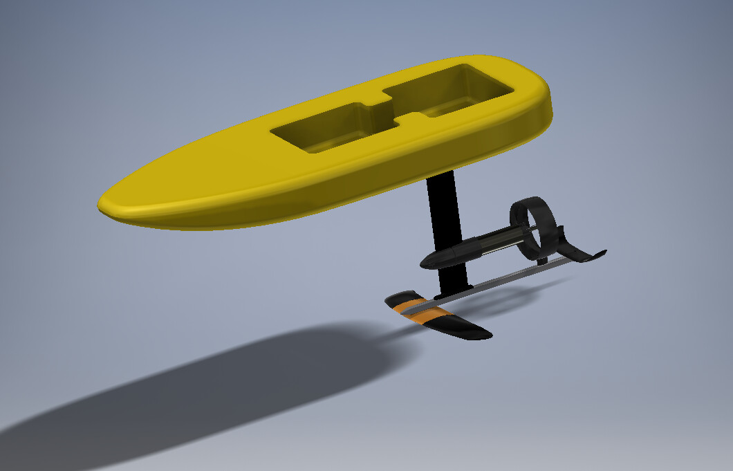
After a friend sent me a video from an e-foil rental in Spain, I was convinced: “I can build this myself!”
With loads of free time due to corona, and it being winter so no other outdoor sports, here are my first plans… I don’t need to end up with a high performance board, as long as it foils and I can surf it ill already be happy…
Drivetrain
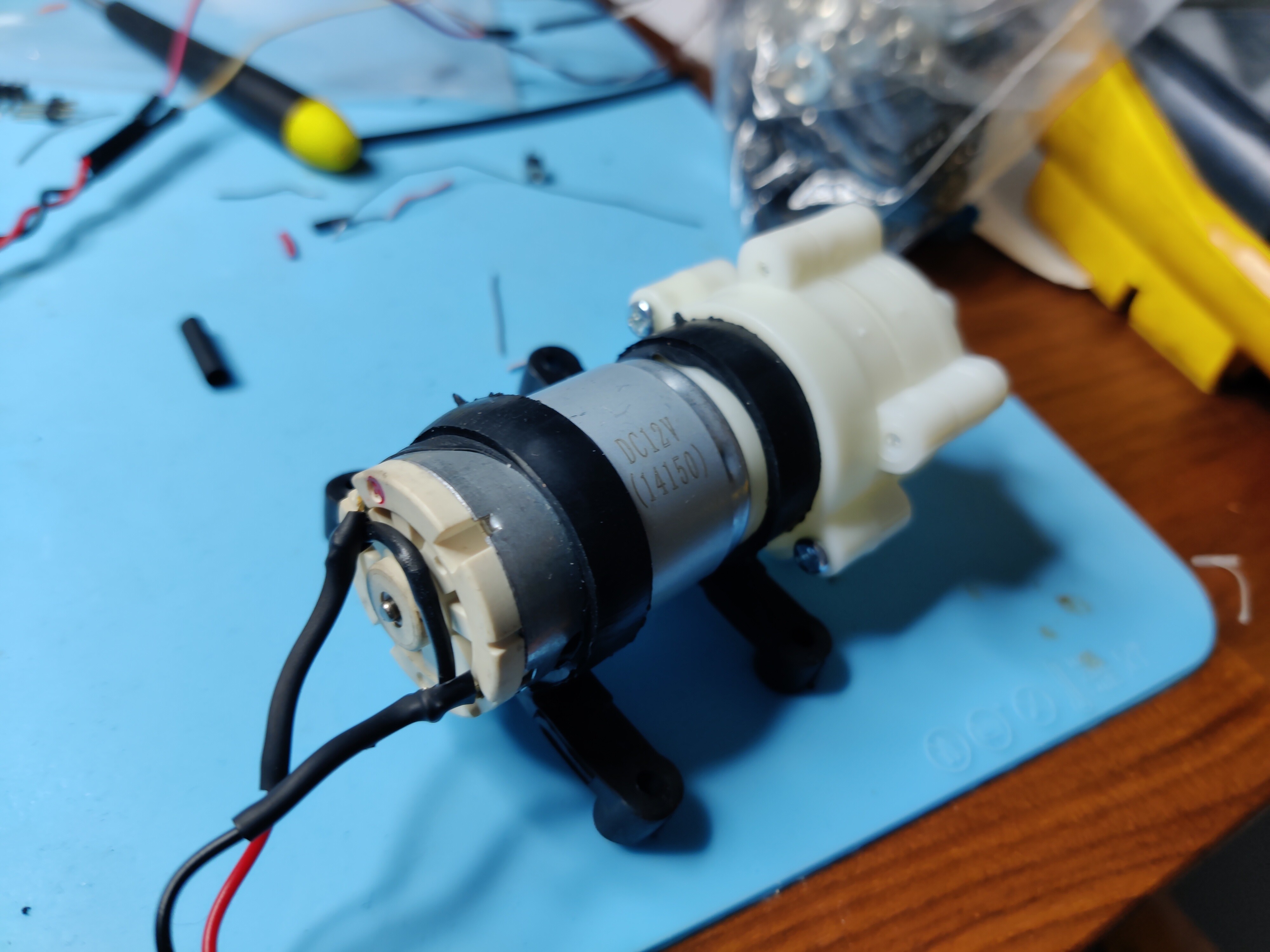
Maytech kit with motor(MTI65162-SF), remote, 300A esc, ubec and pump
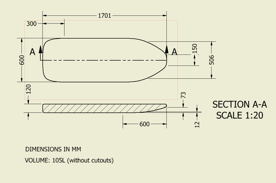
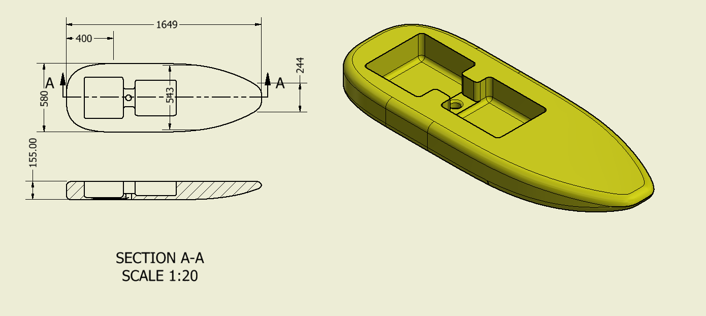
Board
Shaping one myself out of (probably XPS) foam and glassing it with fiberglass and epoxy. The mockup is below. It has a volume of about 105L, but that will probably be reduced a little after shaping and making cutouts.
Any suggestions about glassing shedule? which mat weights and how many layers?
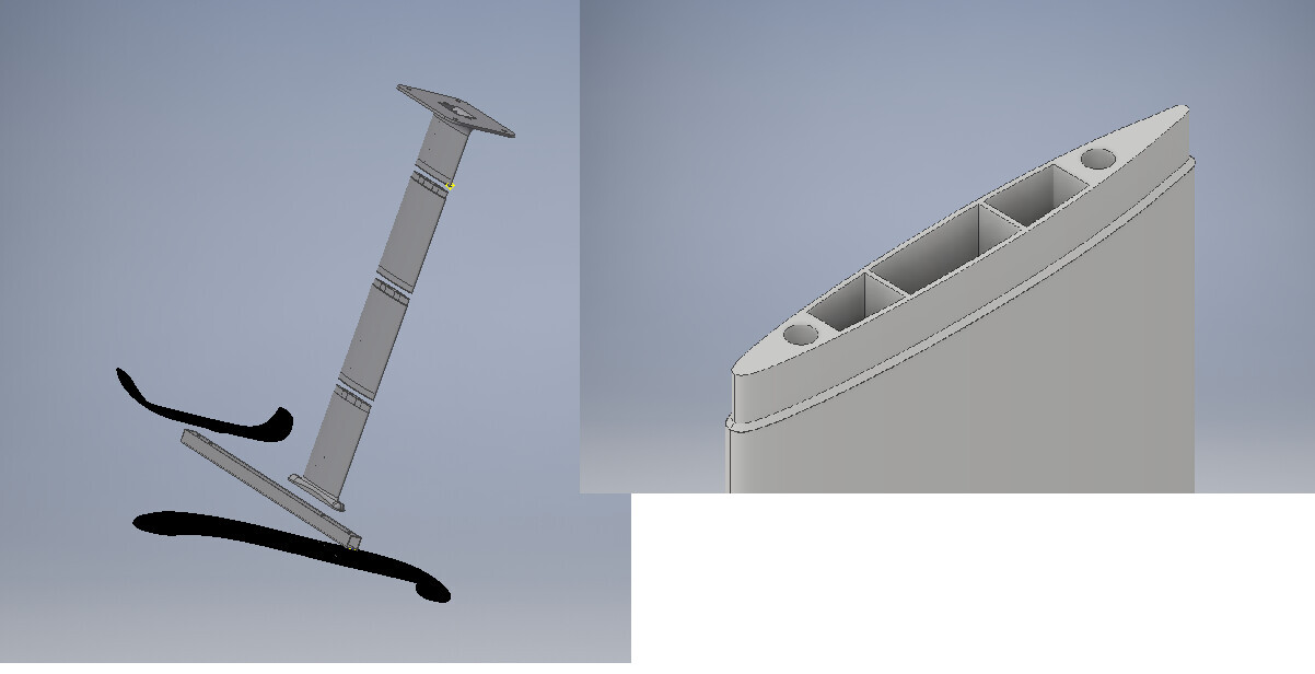
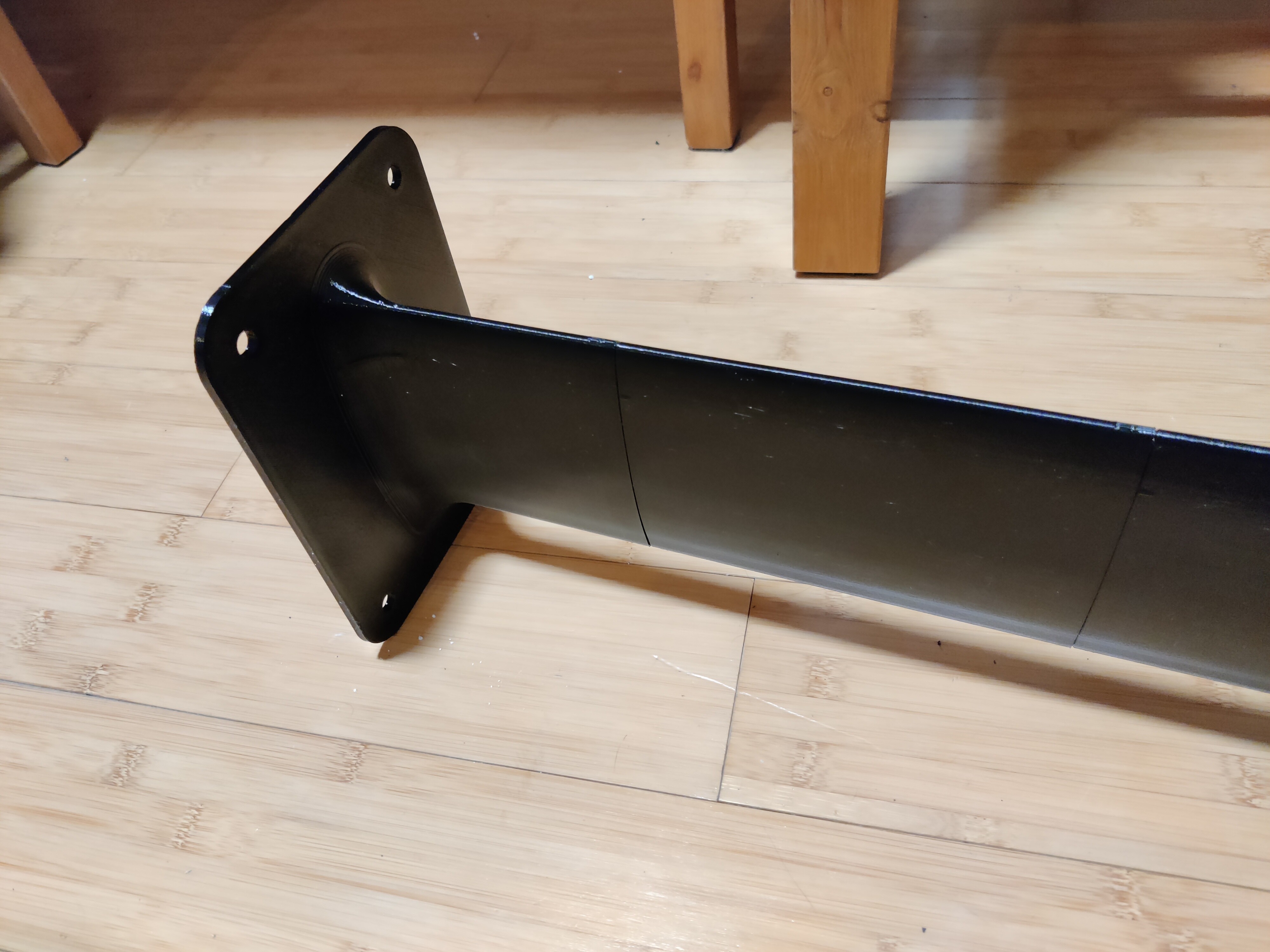
Made of multiple parts to be printed in PETG. NACA0010-35 profile. Room for cables and pump tube.
The holes are for threaded rods to pass trough, and bolt the whole length together and give it some extra stiffness. They will be epoxied in the holes. And the whole mast will be covered in fiberglass as well. No sure whether the stiffness will be enough, but I want to give it a go anyways…
Should I go for carbon fiber or will I be able to get adequate stiffness like this? How stiff does this thing need to be anyways?
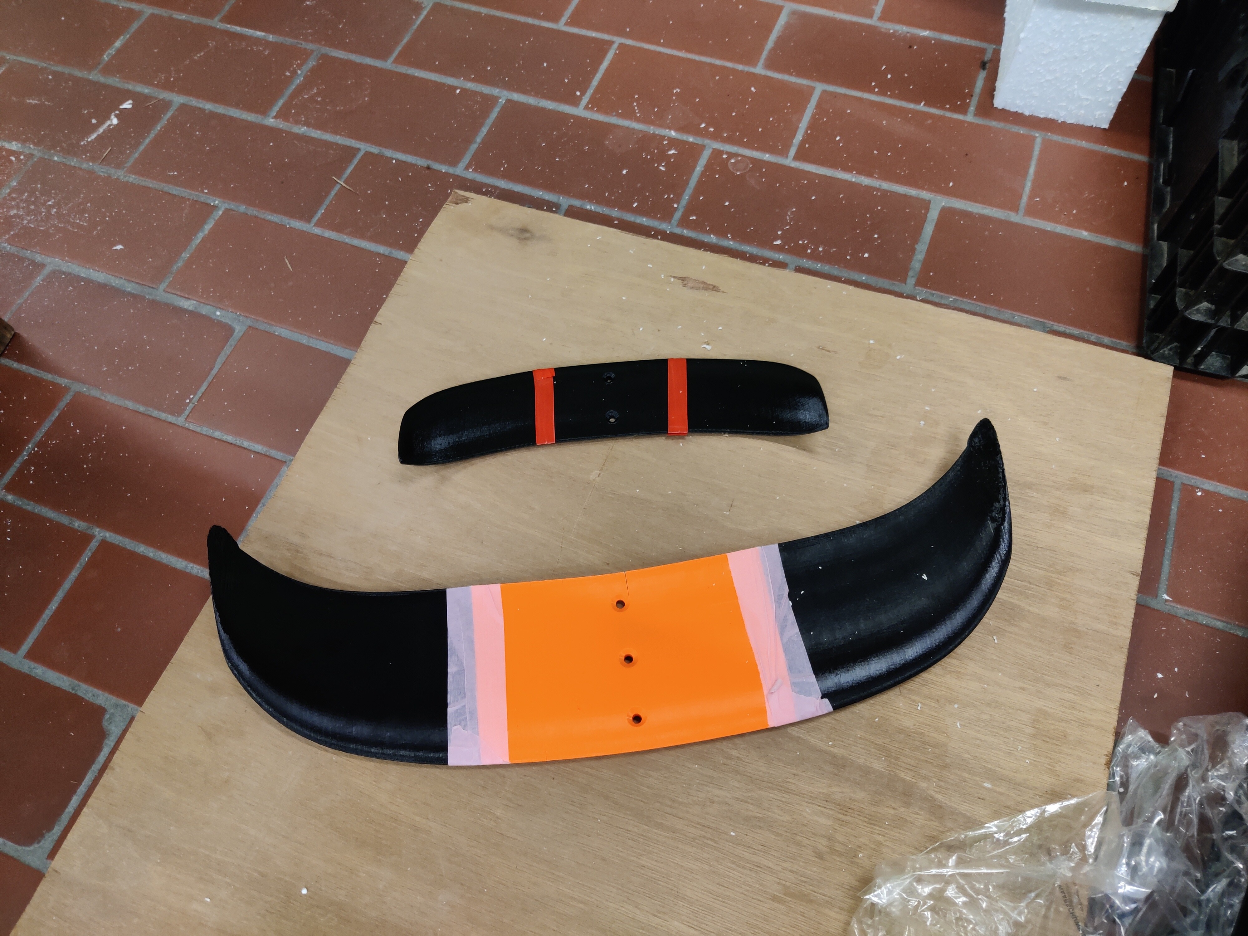
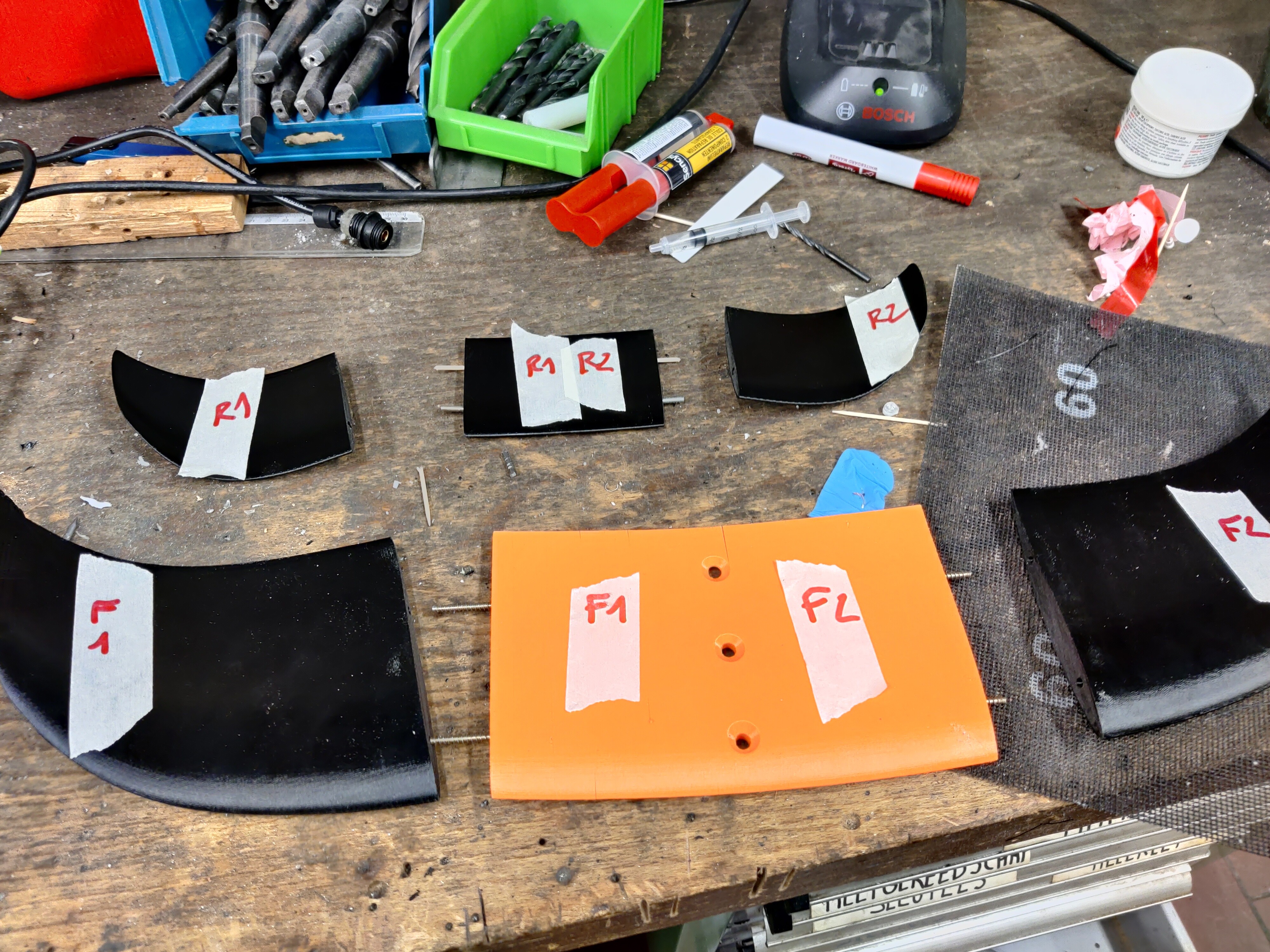
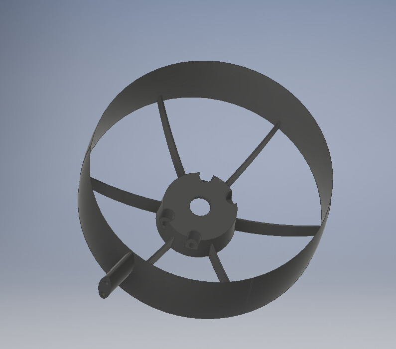
The wings I found on thingiverse: Kite Foil by Straub - Thingiverse
It is based on an Eppler 817 profile - Wing area ~600cm2 / 200cm2
Cause I’m not yet sure about the position of the mast on the board, I plan of making rail boxes to give some freedom in placement and adjustment.
I’m aware I can integrate the motor mount in the mast since I’m making everything from scratch, but I decided against that to have a bit more freedom in placement of the motor and such.
A few more questions I haven’t figured out for myself:
The mast, since it is hollow. Is it normally waterproofed such that it does not get filled up with water? or is it the opposite, not filled, and a nice little drain hole at te bottom the evacuate the water when it starts foiling?
Length of the mast: How long, pros and cons of a longer or shorter mast
Distance between front and back wing?
Position of the mast on the board. How critical is it?
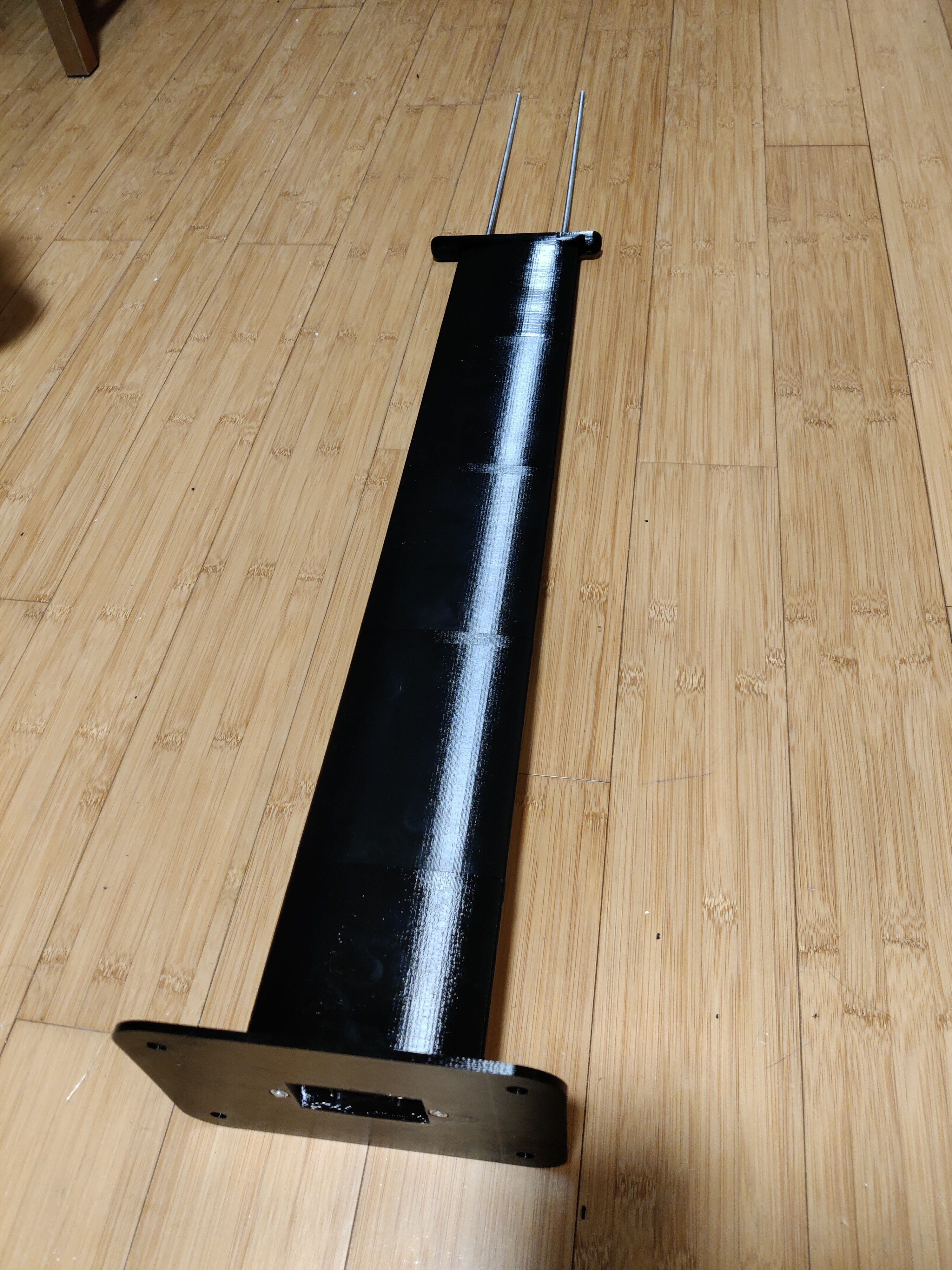
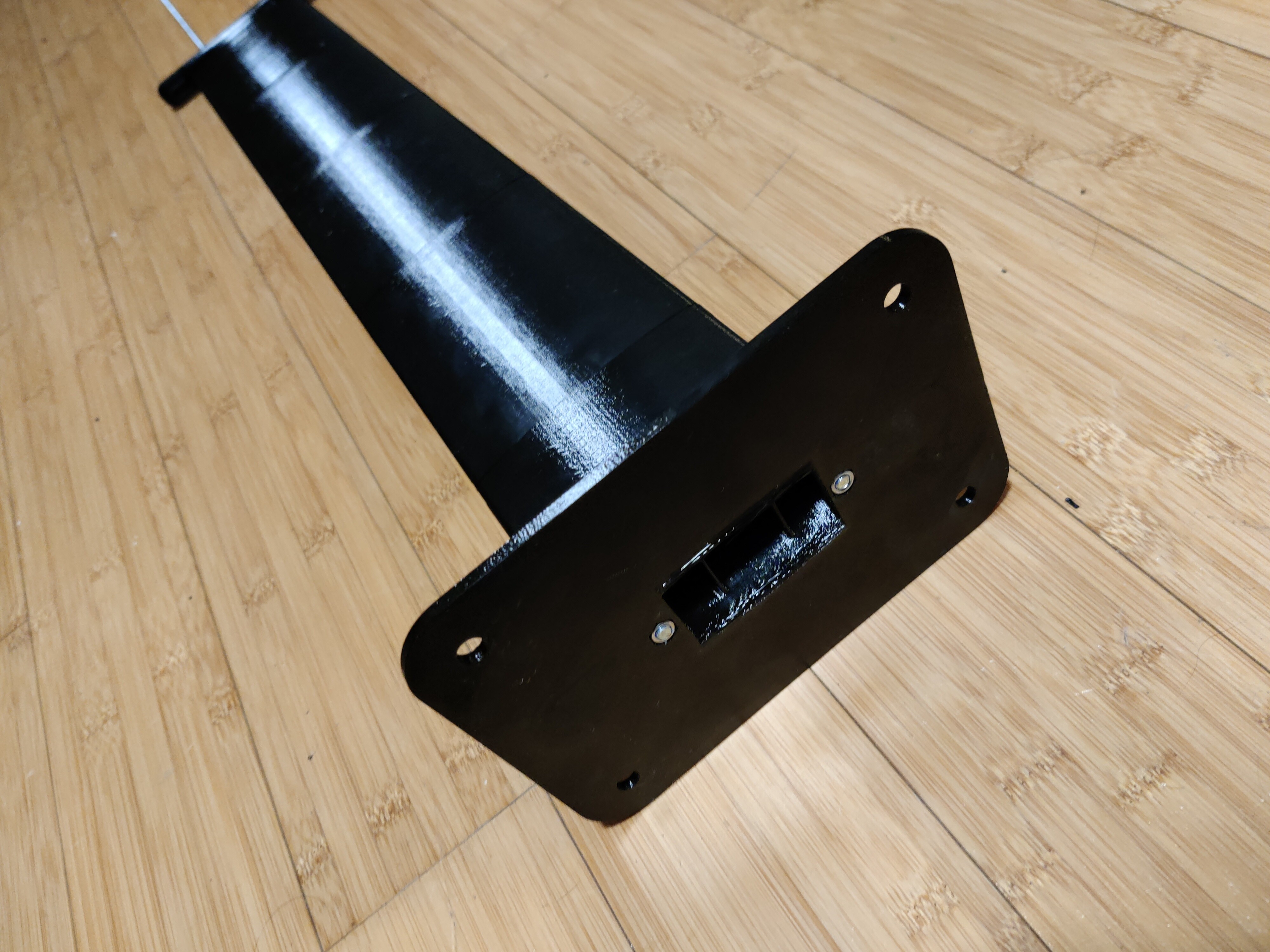
Finished the mast some time ago but did not post it yet. Its quite stiff, but I’m not sure yet of the final stiffness. If it is not stiff enough after laminating it and epoxying the threaded rods in there, I might redo it and attach aluminum bars to the side to add extra stiffness there.
Your mast looks amazing, I would go for aluminum bars reinforcement as you said but they should be thick enough, probably overkill but in your case, I wouldn’t go for less than 4mm on each side yet you would have to chisel your mast profile (or reprint) so the bars fit flush with your mast curve, you should then probably do multiple wrap layers (carbon outside) with vacuum bagging, its probably the best way for achieving high tensile strength parts
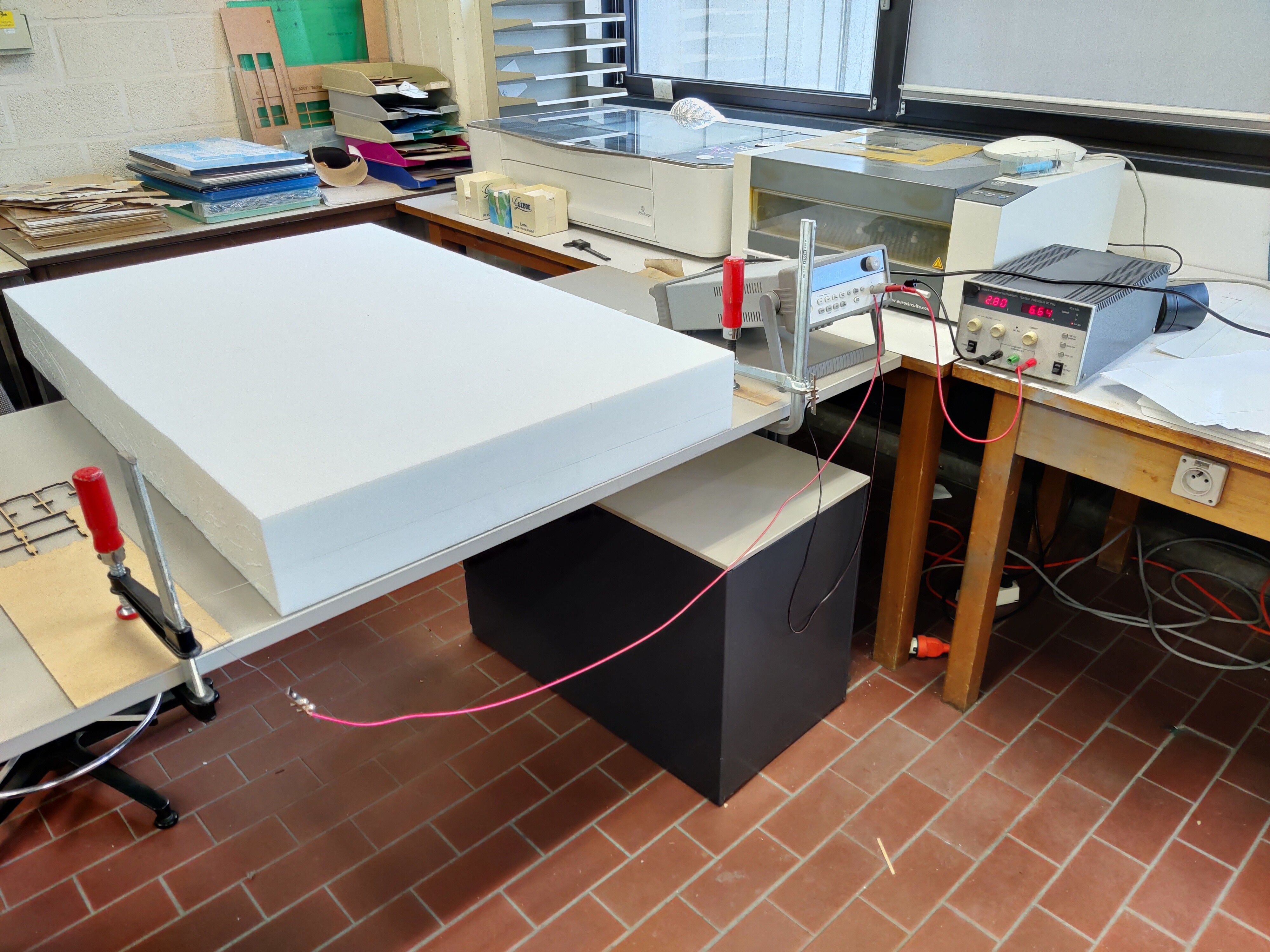
Busy day today! Got my XPS foam. Jury rigged a foam cutter to split the leftover foam to increase thickness. Two lab power supplies in parallel for a total of 18 amps. Stripped a solid core wire to serve as heated wire. A man gotta do what a man gotta do…
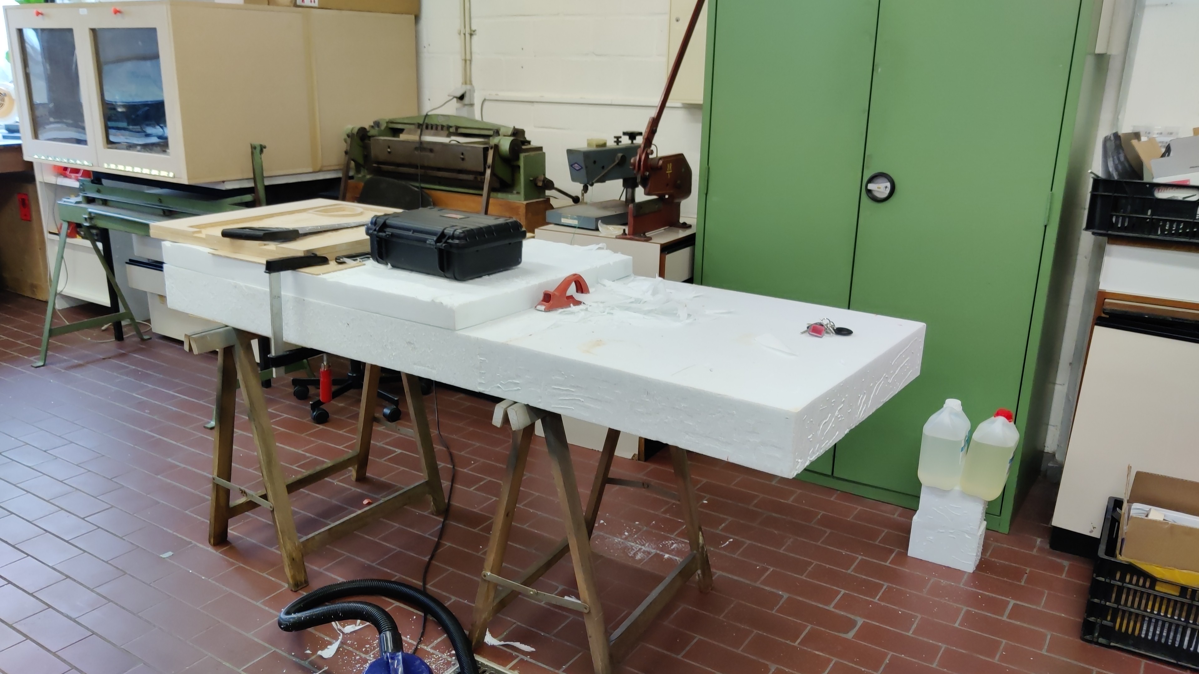
Test fit with the extra layer of foam (12cm + ~6cm). Going to shave it down to a max thickness of 15cm. The black pelicase is for the batteries, so I need a 12cm recess so that it would sit flush with the top of the board.
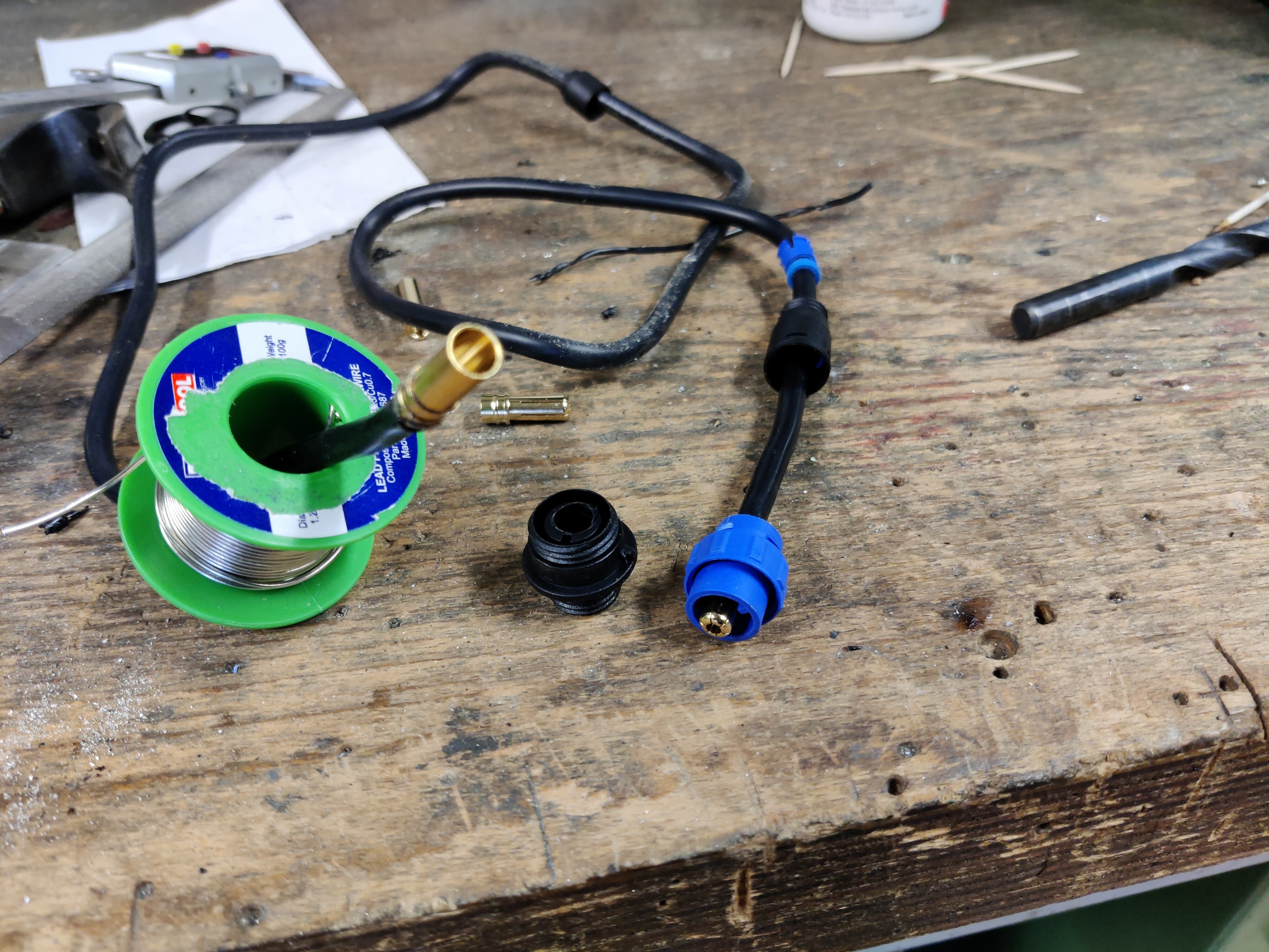
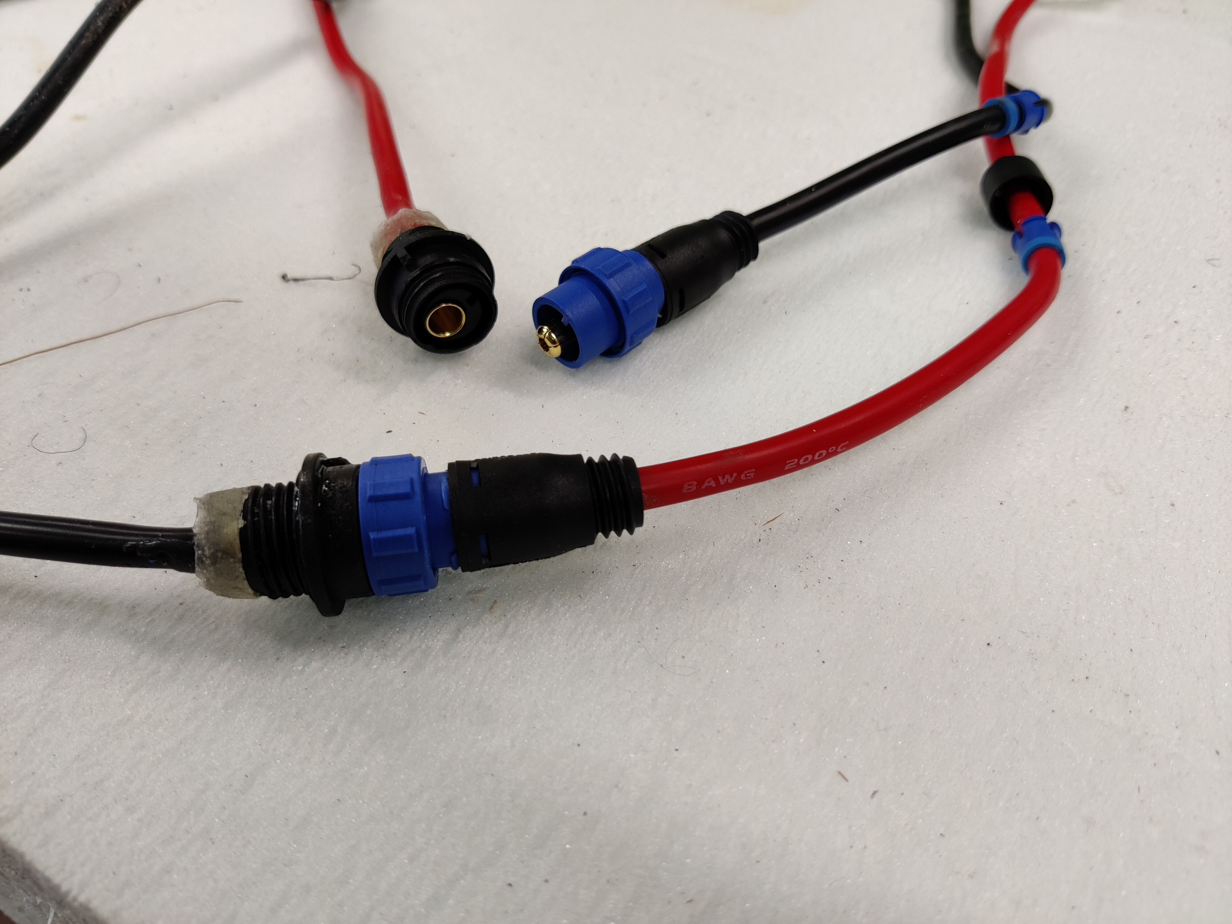
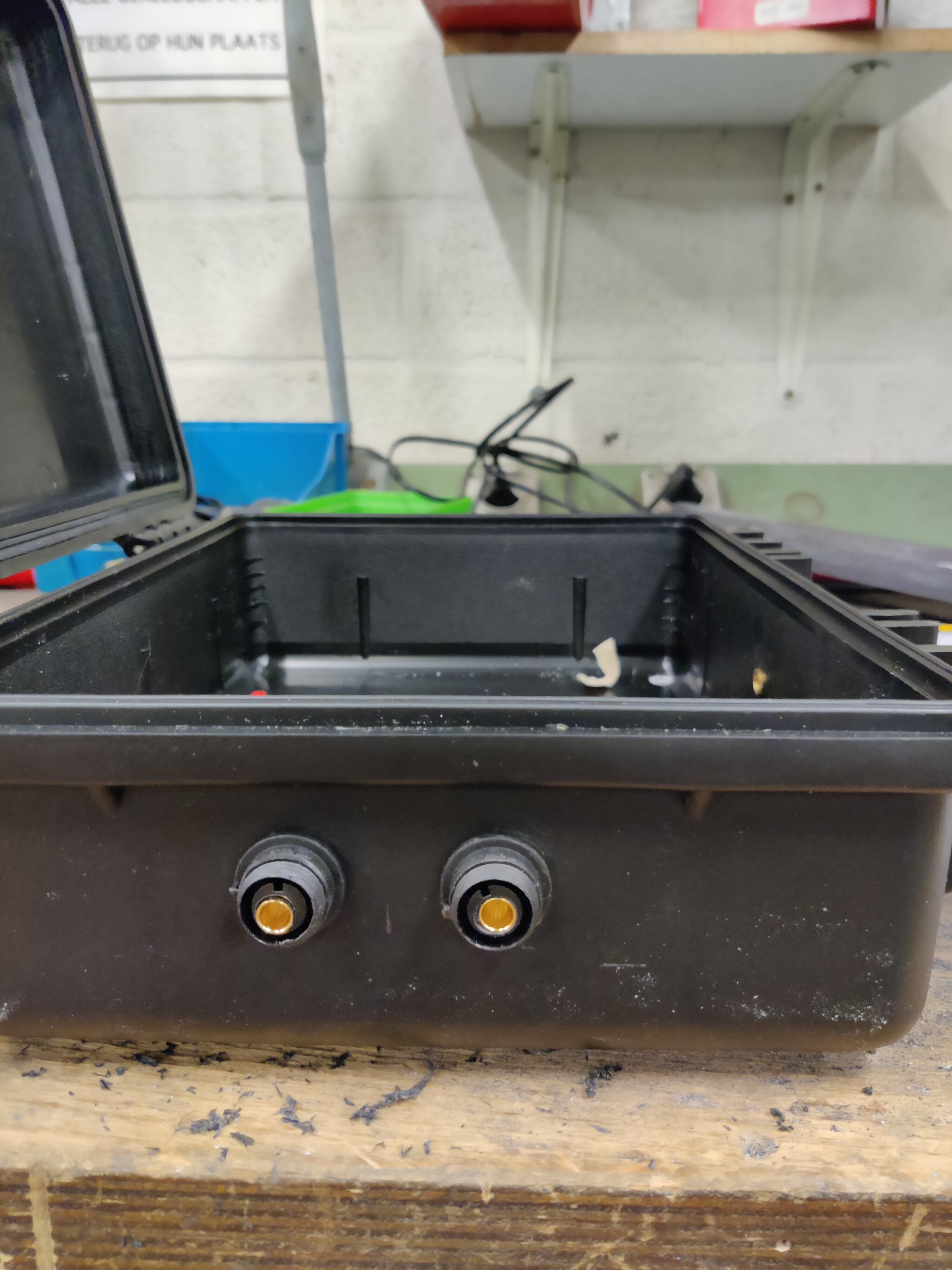
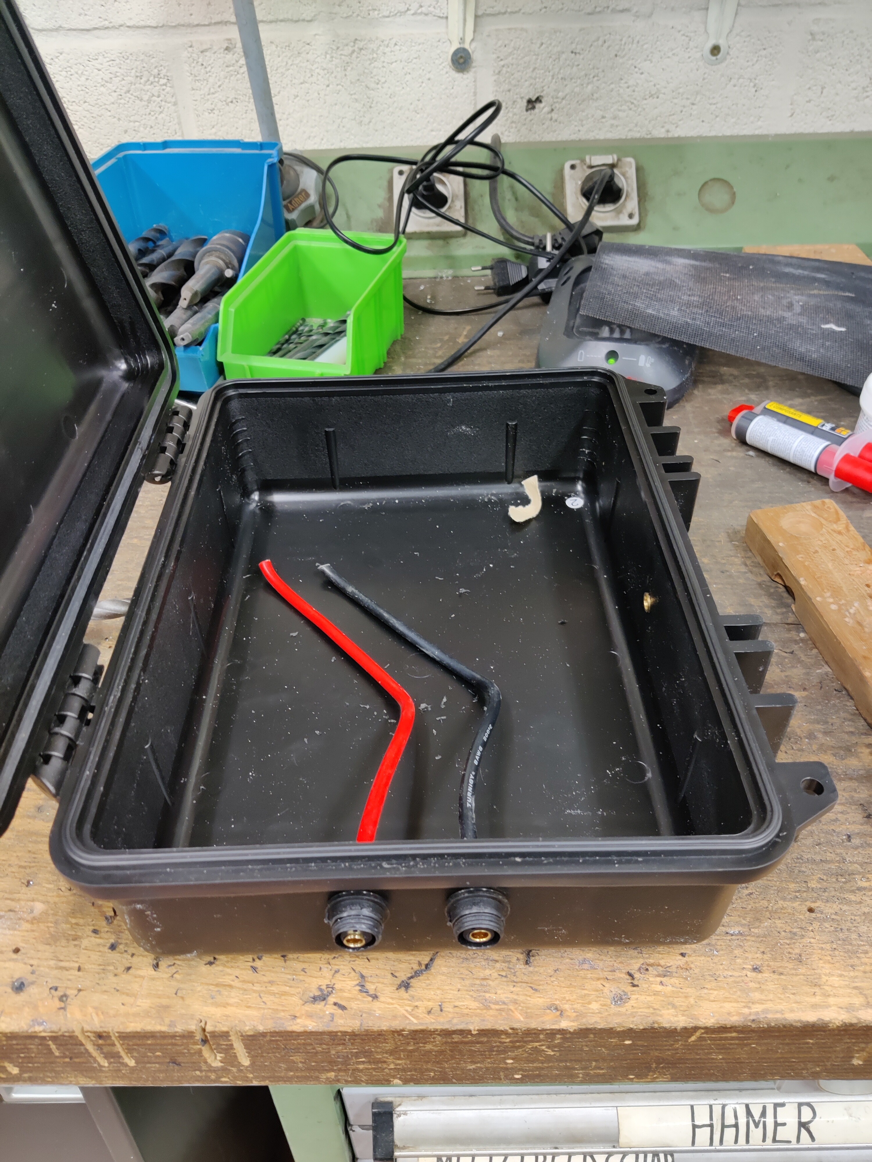
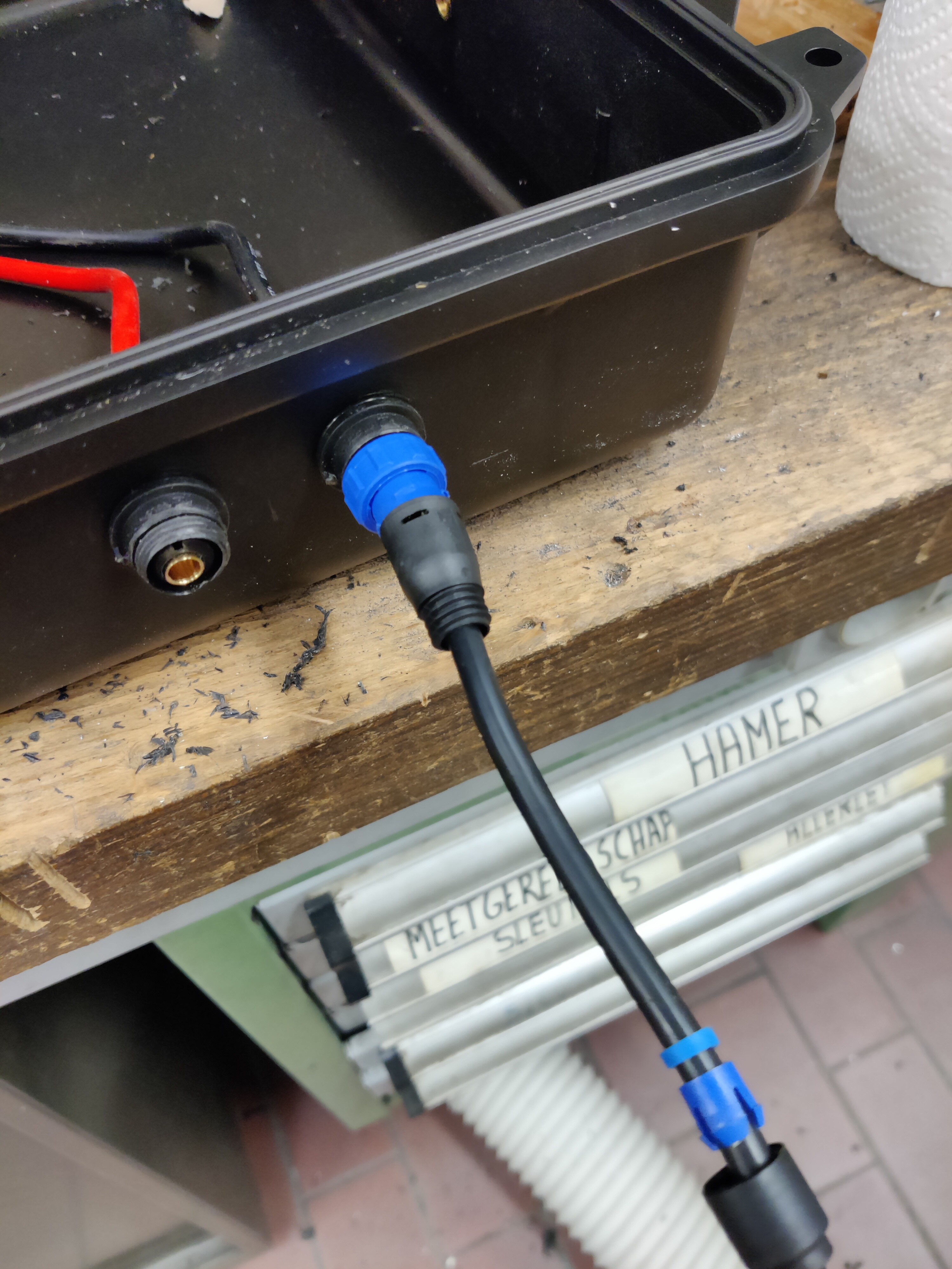
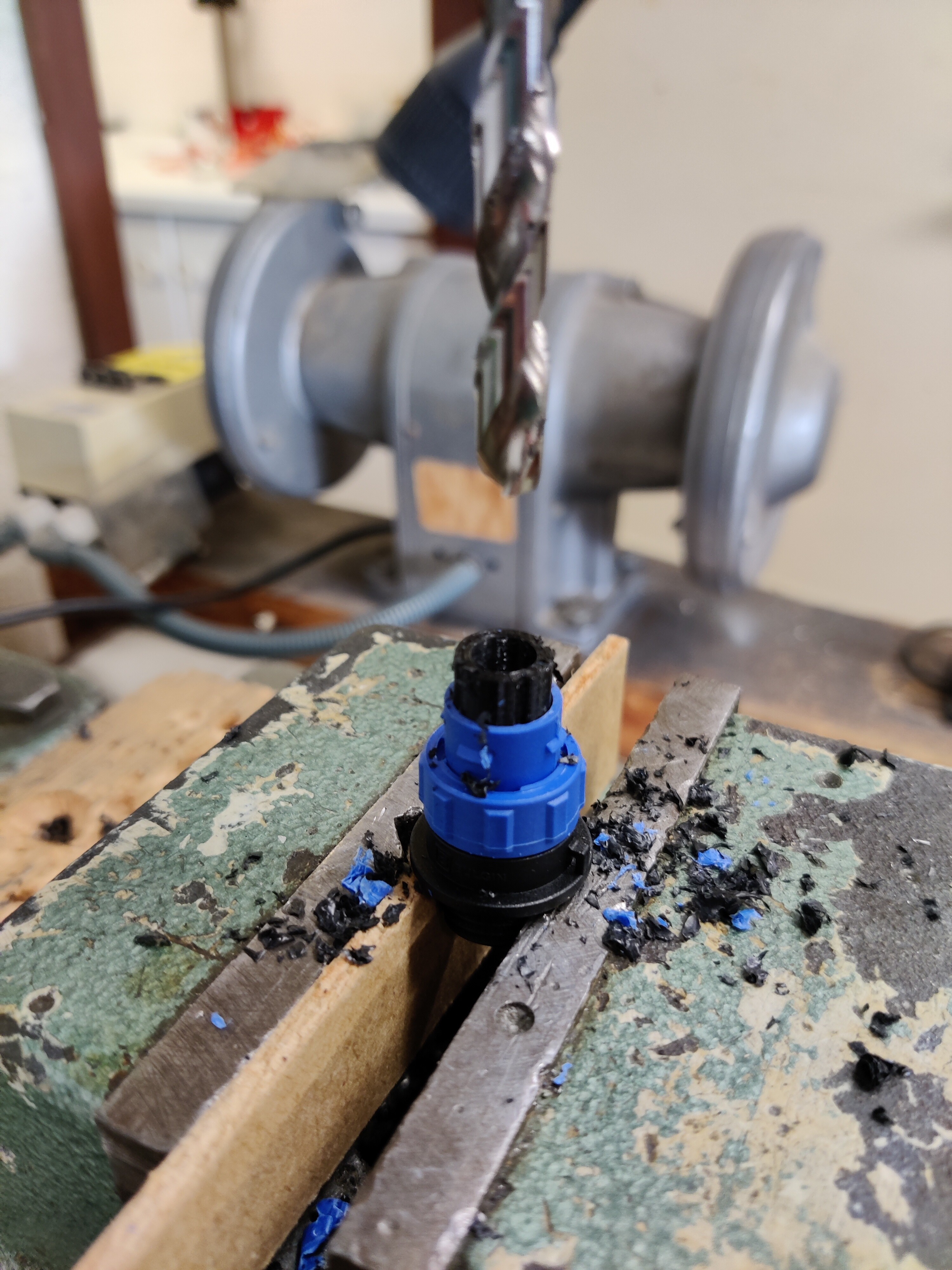
Made some IP68 high current connectors for which I wouldn’t have to sell a second kidney.
Started from a Bulgin buccaneer 400 connector. (PN: PX0410/02P5560). Its made for 6mm cable which is a perfect fit for the 8AWG cable I have. Drilled out the middle part to fit an XT150 instead. Panel mount side has a countersunk drill for a better fit of the XT150. Epoxy on the panel mount side to nicely seal everything. The connector side still needs a bit of silicone for extra sealing just in case (might be redundant since that part is already IP68 with O-rings all over the place.
Hey, I’m also also planing on building a efoil. and was wondering where you got that big block of XPS from, I’m in the USA and am looking at buying three blocks from Home Depot, but if you could tell me where you got your foam that would be great
I live in Belgium so any advice I give would probably be useless. I got mine trough a friend that works at a fablab where they use it for prototypes. You can find EPS and XPS plates as isolation material for construction. Maybe that would help…
Board is redesigned slightly to adapt for the changes so far. Volume withouth the recesses for the electronics boxes: 119 liter. A bit more volume that I’d had liked but it’ll do. Might shave off some more while shaping…
Thanks for the feedback. Indeed on the mockup its a bit much forward. I’ve read on here about 20% of the length of the board. But is that the front/back/mid of the mast or of the front wing?
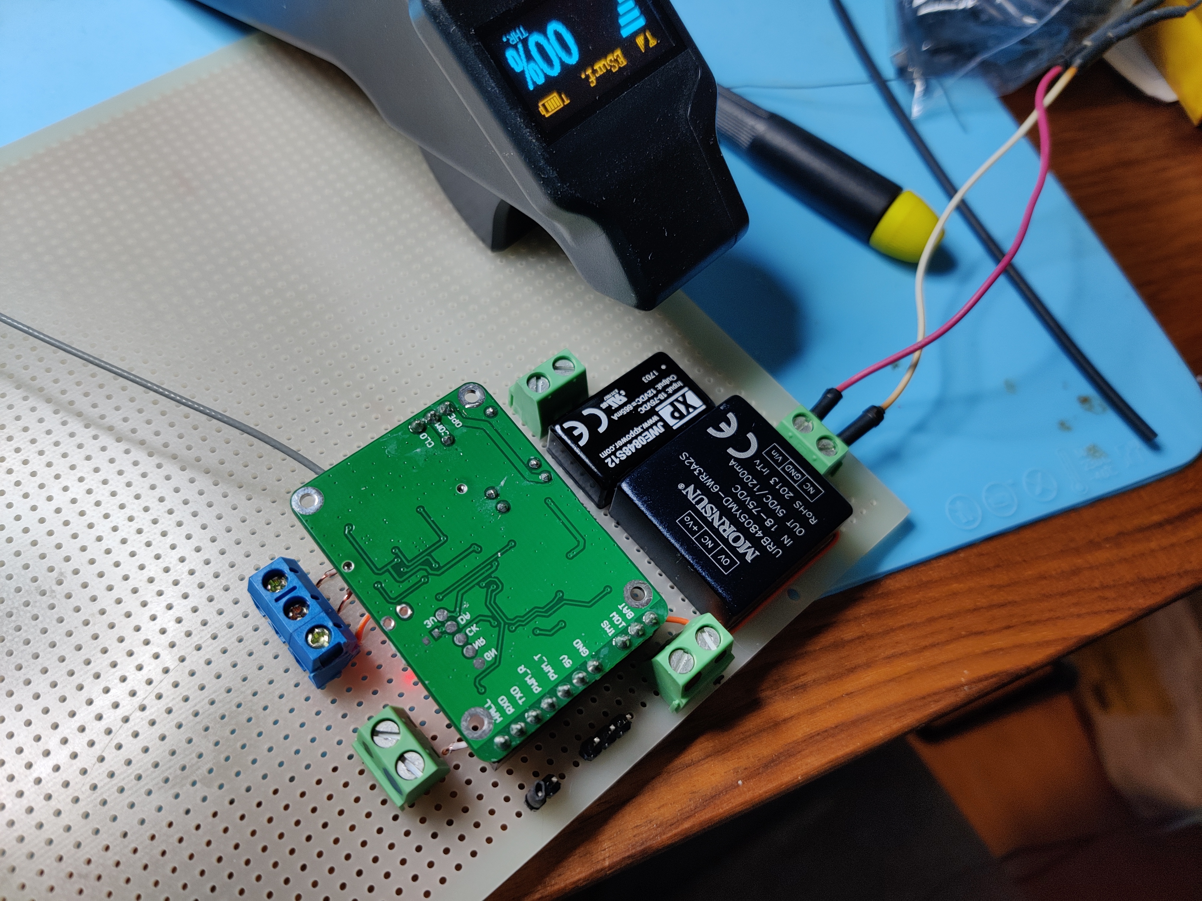
Soldered a PCB for the receiver and power supplies instead of creating a gordian knot in my enclosure. For a one-off, no need to design a custom PCB so time to dust off my shabby prototyping skills…
On the board: 5V power supply for the receiver, 12V power supply for the motor, the receiver itself, connector for the ESC and heaps of screw terminals.
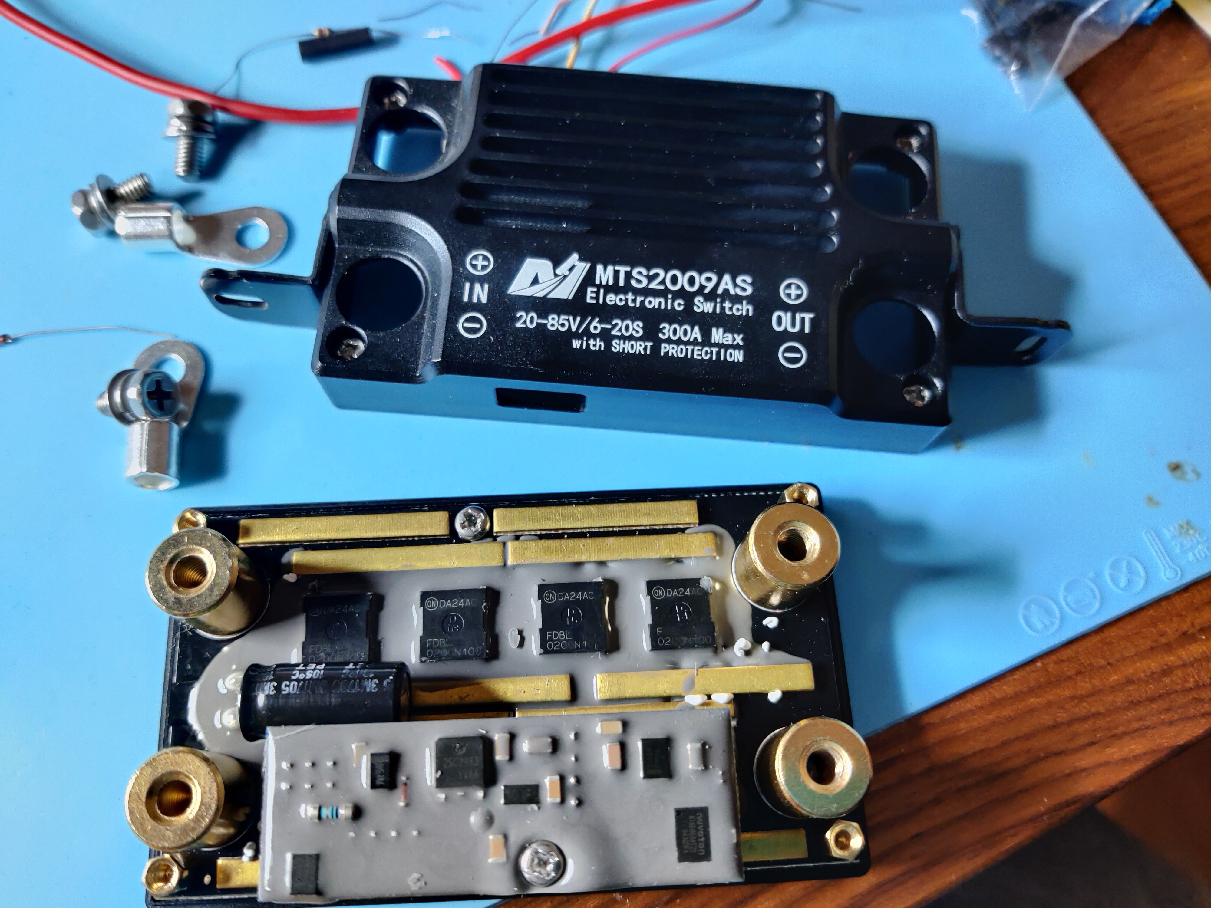
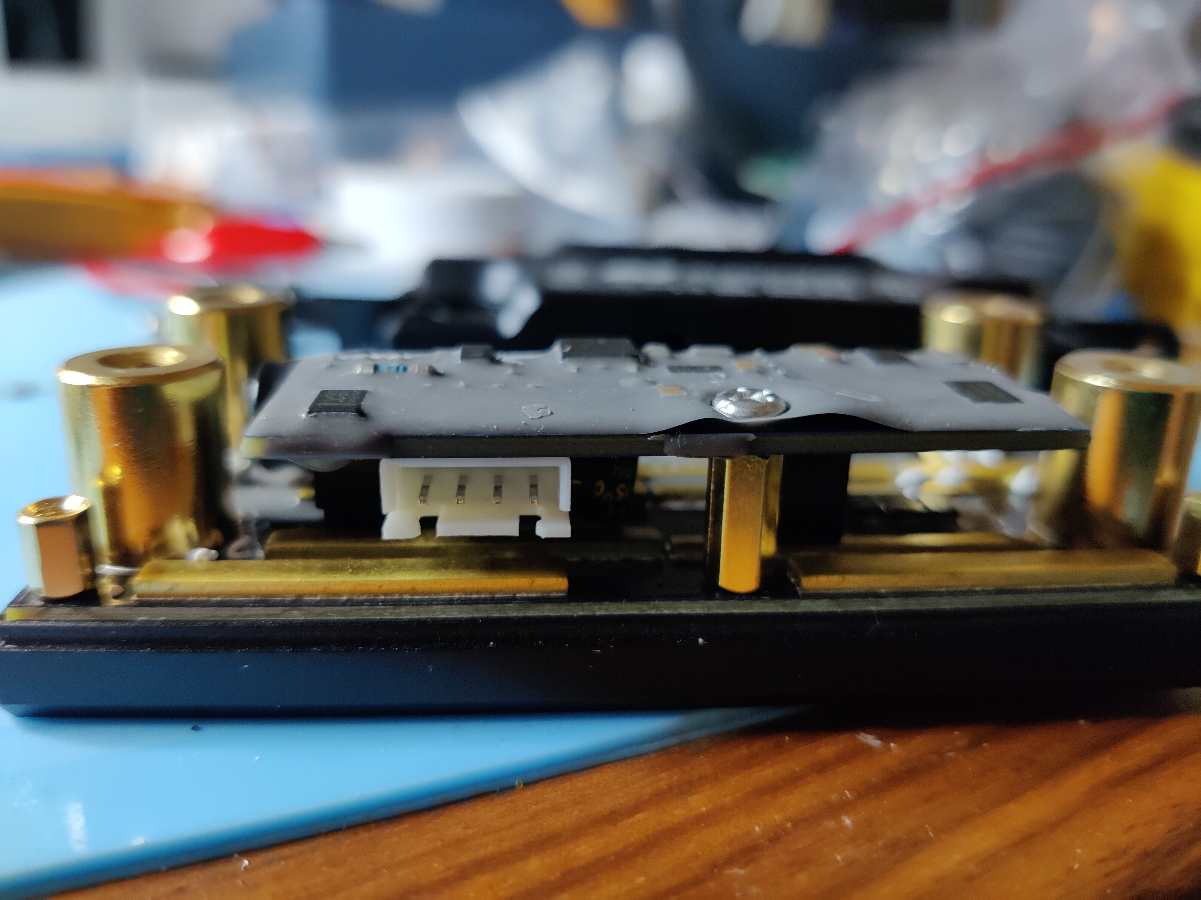
Opened up my maytech anti-spark switch (MTS2009AS). I was hoping to be able to wiring my Normal-Open boat deadman’s switch in. Since I couldn’t learn a lot from the measurements on the connector pins I opened it up. Not sure how it detects the power on, since you need to short it with VCC to enable, but it stays 0.7V below VCC. I guess something with a diode or a transistor in there creating a voltage drop. ¯\_(ツ)_/¯ Anyone have an idea?
For other people that want to geek out about the inner workings:
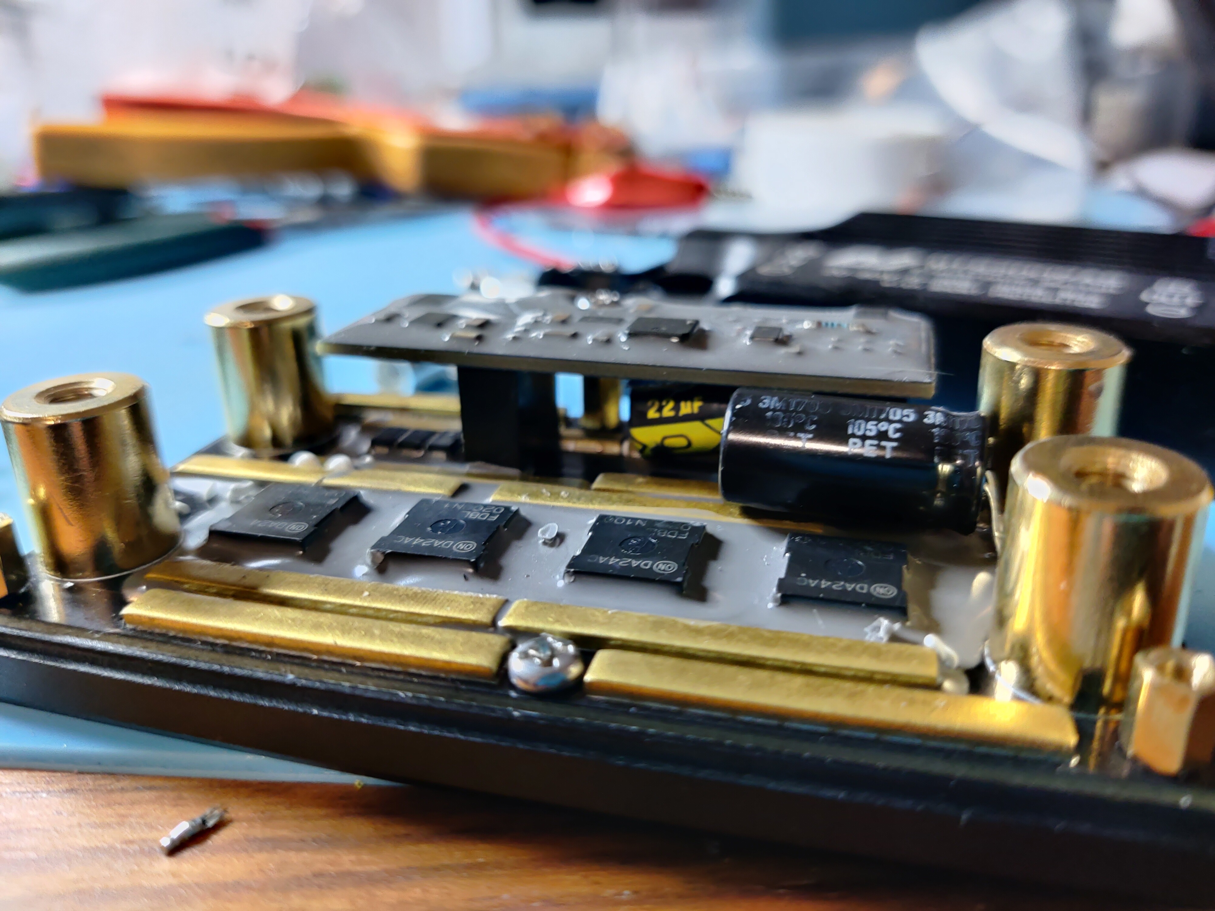
Baseboard contains some (unfindable [DA24AC FDBL 0200N1]) OnSemi N-MOS transistors. One big capacitor and some diodes. Control board has the following components:
DCDC psu module on the bottom
LM393 opamp
2SC29 NPN transistor
Nuvoton n76e003 microcontroller
NCP5106B gate driver for the NMOS highside load switching
Some miscellaneous diodes, resistors and capacitors hidden beneath the grey putty.
I have something like the same idea:
I want to switch the Maytech MTS2009AS Anti-Spark with a HAL sensor. A magnet on a leash should serve as an emergency stop switch.
I want use a NJK-5002C Hal sensor for this?
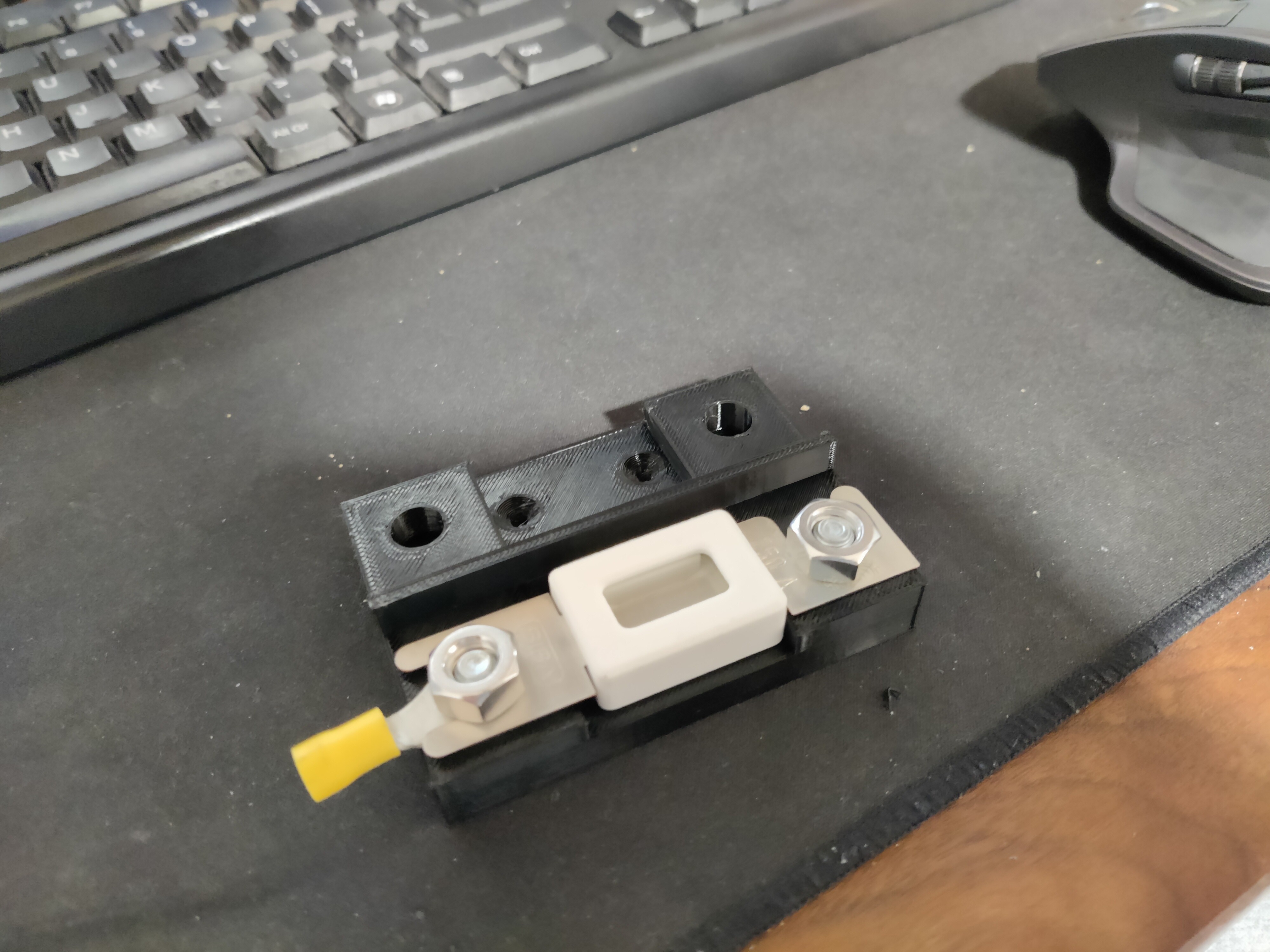
I am still looking into it. Once I figure it out ill let you know. In any case a reed switch in series with the power switch should work (cut the yellow wire). But the reliability is probably less good.
First big fail. Tried gluing the XPS foam together for increased thickness (see previous post) but after three days it still did not stick. The glue I chose probably needs contact with air to harden. So that was a no-go. Separated the pieces, sanded and now going to glue them with epoxy.
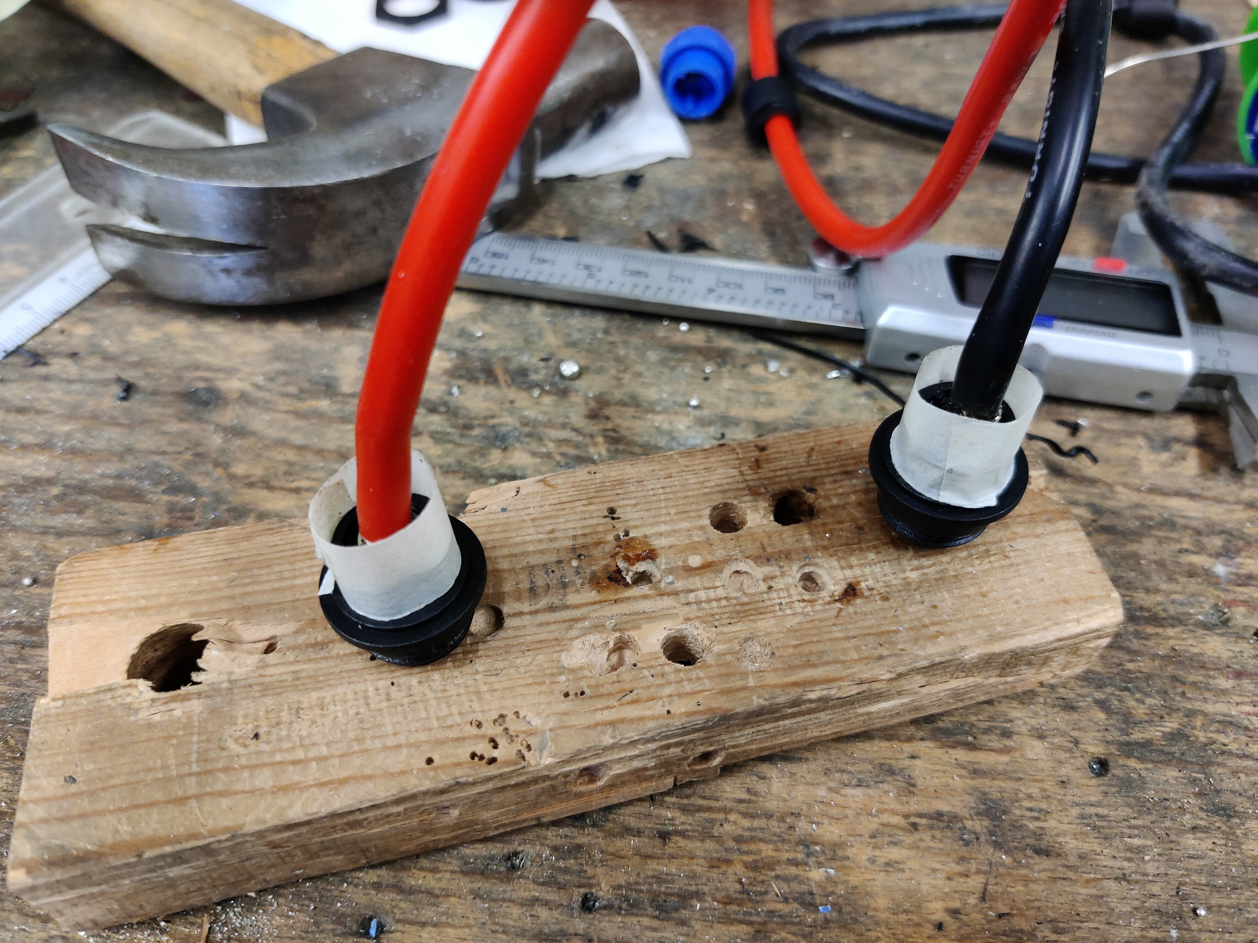
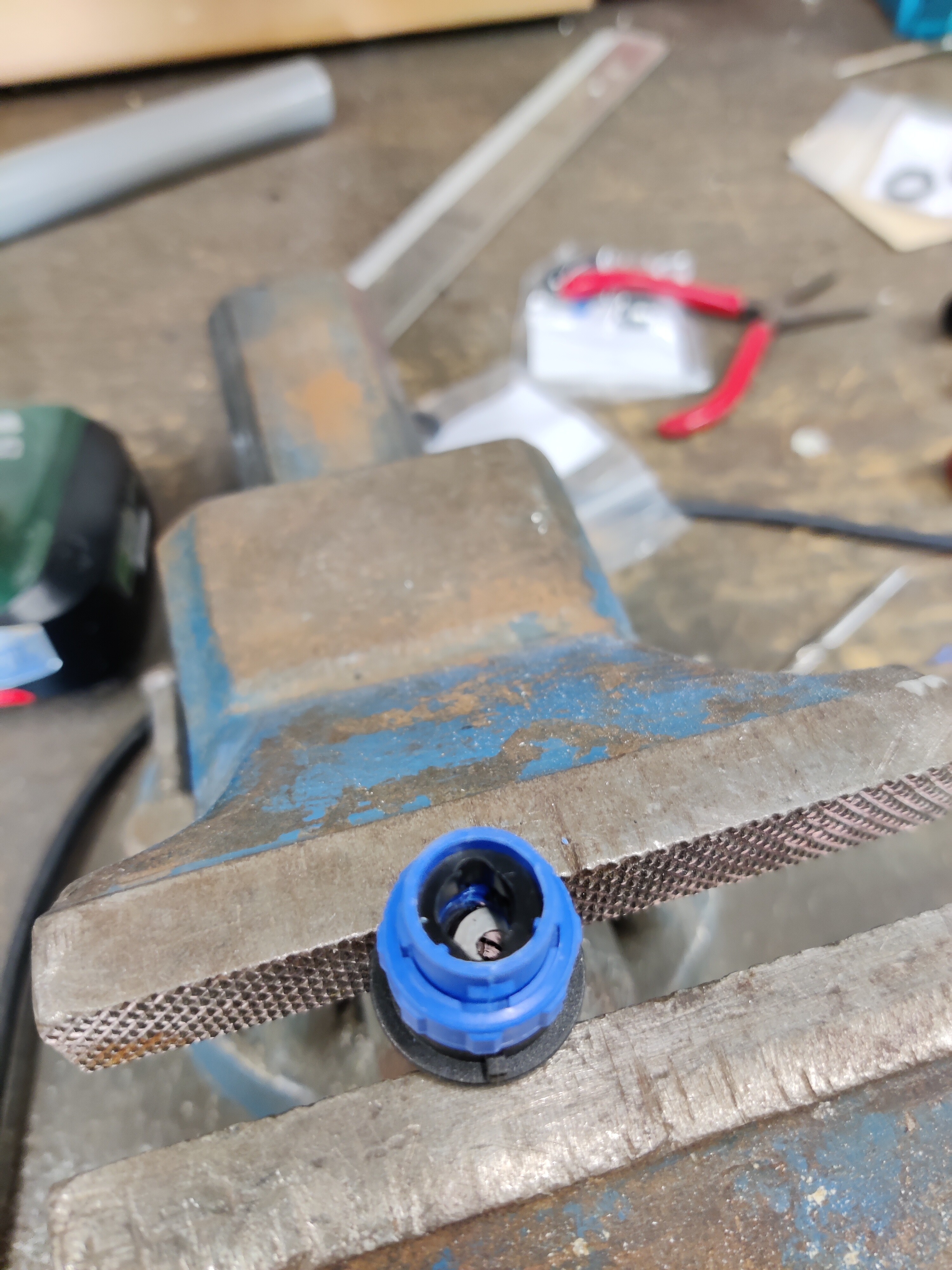
Improved my fabrication process of the connectors. I printed a ring to center the drill in the part. And then drilled both parts in one single go all the way through.
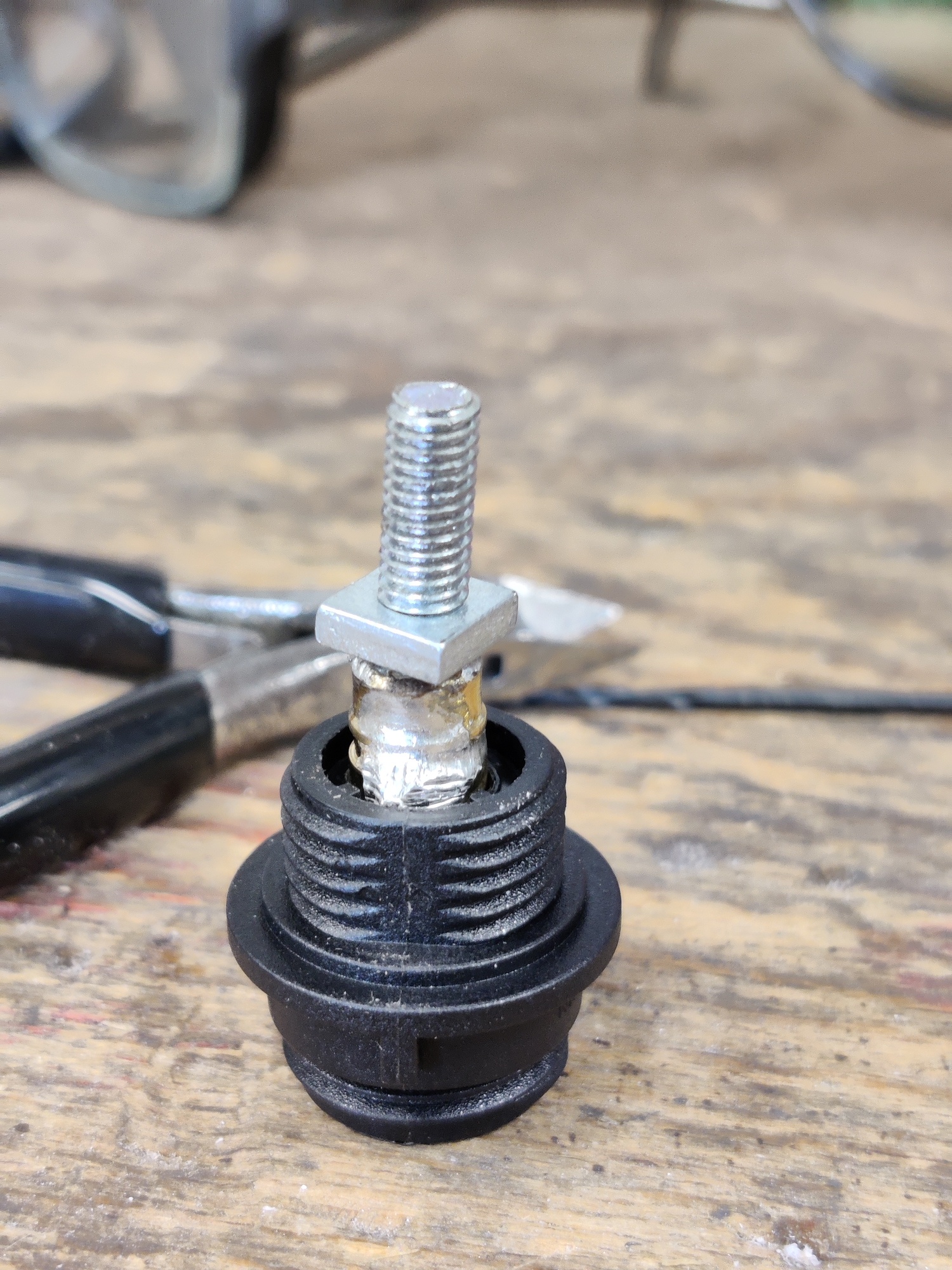
For the motor I’m gonna use the same connectors. But I made a bolt variation by soldering/brazing a piece of threaded rod into the female XT150. And then epoxying it it plate in the plastic.
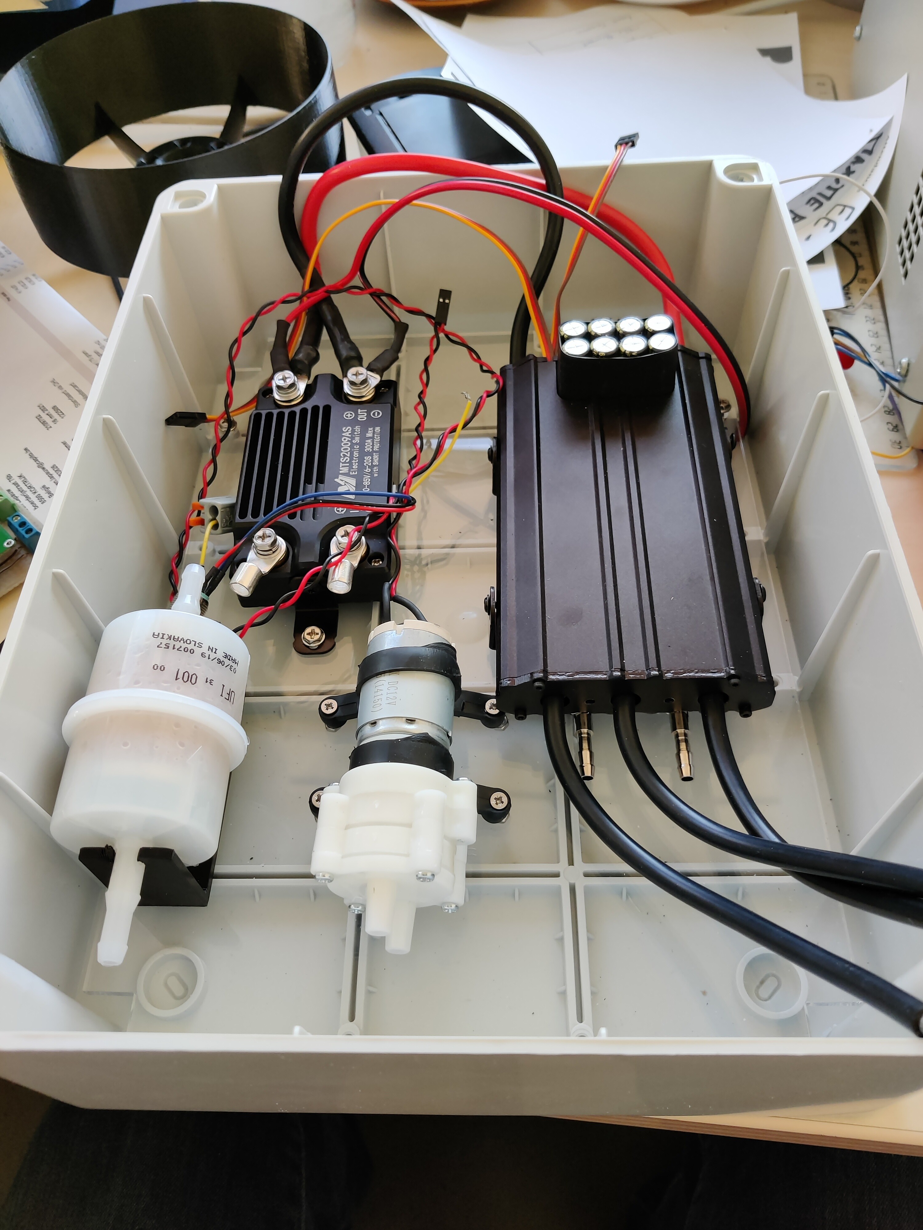
Lasercut an acrilic plate for in the “big ol’ box o’ electronics” Tapped the holes so theres no need for nuts on the other side. I added a fuel filter to serve as a filter for the cooling water inlet. I’m not sure whether this is necessary, but I’d rather have to replace a €2 filter regularly than a more expensive pump, or getting gunked up pipes. Does this make sense or am I just living too much in a fantasy and its useless?
I have some contact with “Agnes” from Maytech and there engineer …
There is no way to use a HAL Sensor without an relay …
"can’t directly use hall sensor, need to connect a relay switch as a transit. "
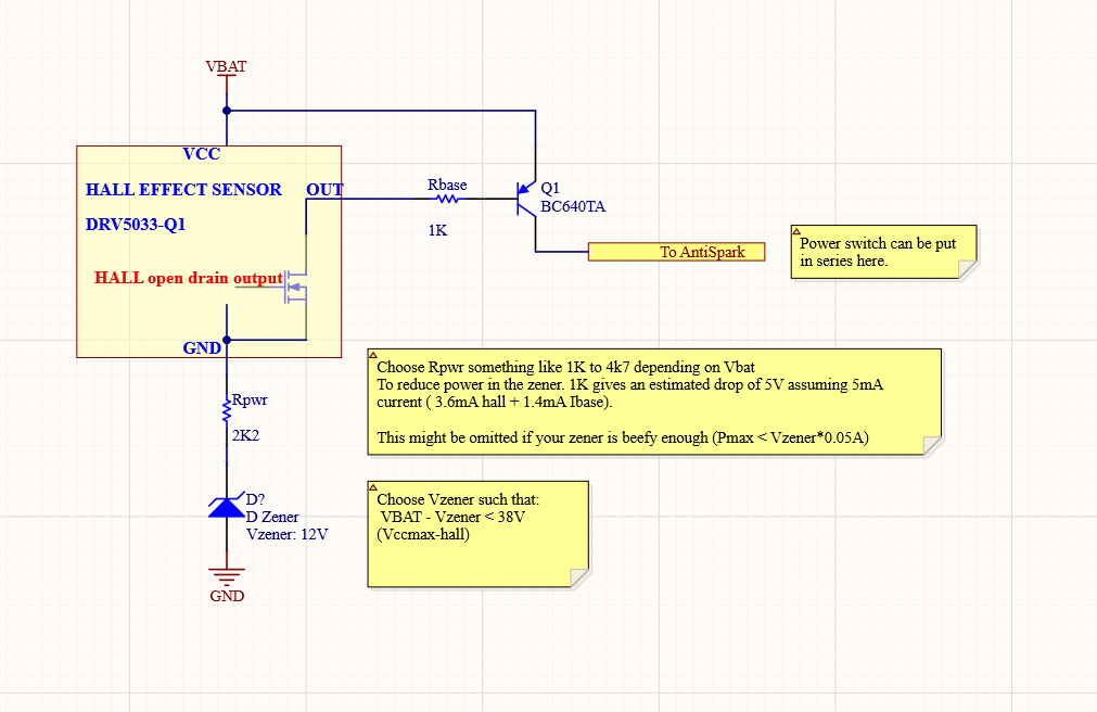
The idea is to use a high voltage hall sensor (which has an internal regulator), and use a zener diode as an additional voltage regulator which will offset the hall-sensor ground. The open drain of the hall sensor will sink current of the base and it will pull the connection high to Vbat which is normal operation. I think Q1 could also be replaced by a normal P-channel mosfet with a Vds > Vbat and a Vgs > (Vbat-Vzener) [or choose Vzener large enough to keep Vgs limited] + a pull-up resistor.
The hall sensor chosen is a unipolar non-latching one, so magnet orientation should not matter.
It is not exactly super low power since it will induce a constant current draw of about 5mA. So for long term storage the Vbat needs to be disconnected. I put some rough notes on how I would size this circuit. Rbase needs to be calculated based on the current you need and Vzener, but probably something in the ballpark of 10K to 4K7 should not kill Q1. The power dissipation of the zener is Vzener*5mA assumed so choose one with large enough power dissipation.
I’ll probably order the components and try it out soon. Ill get back to you when I tried it.
[Full disclaimer: fairly confident that this could work, but I don’t take any responsibility]