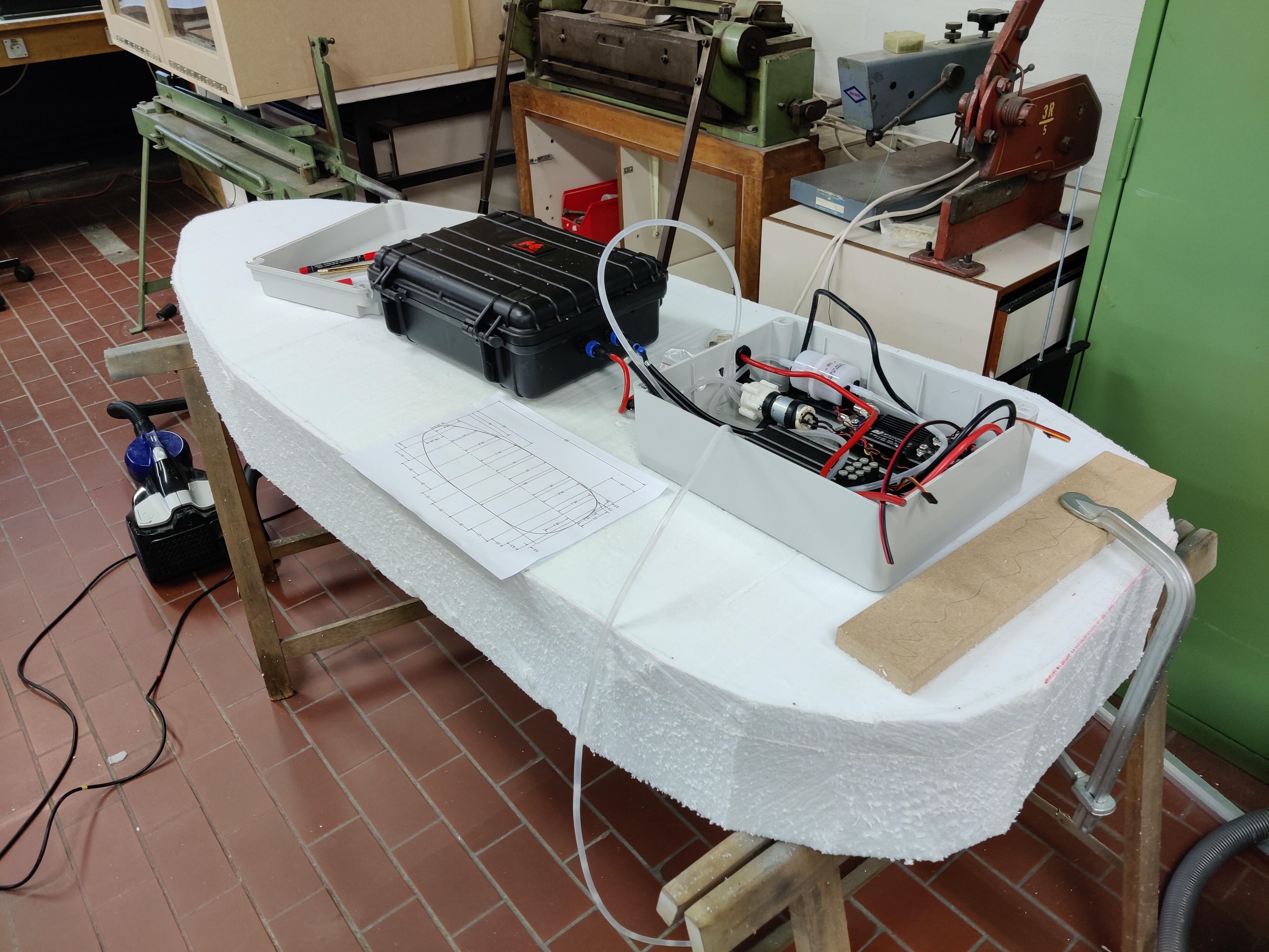
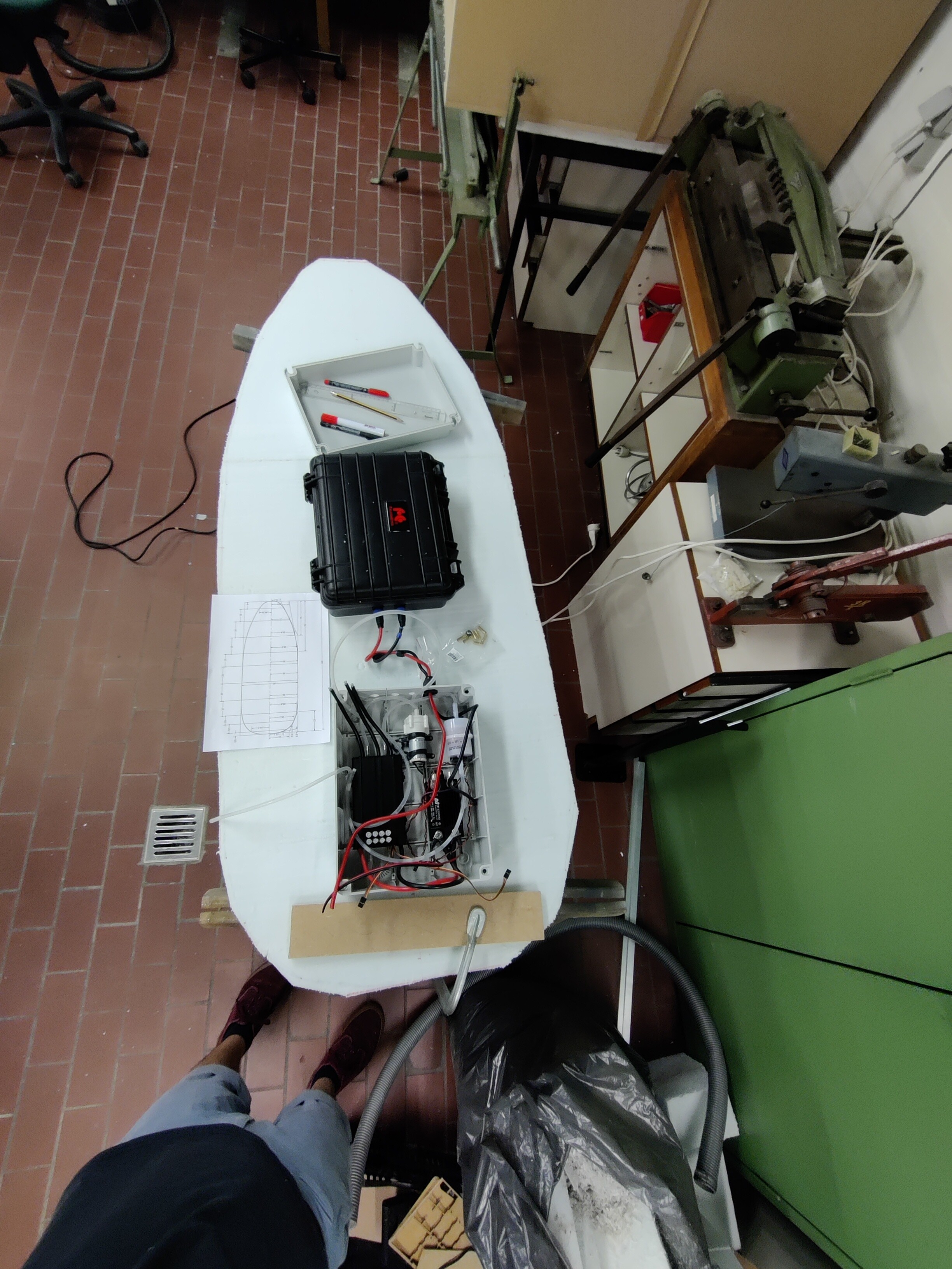
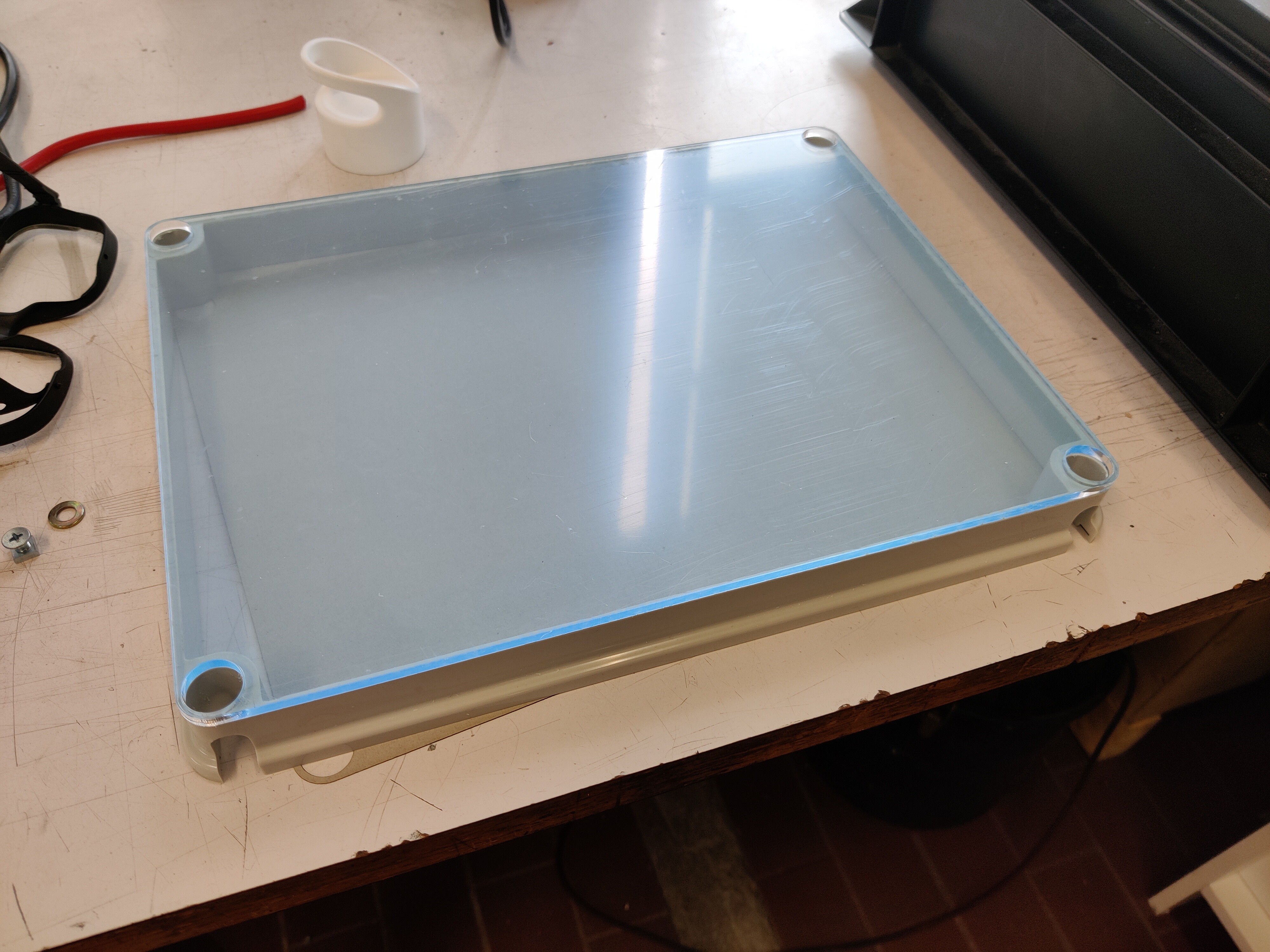
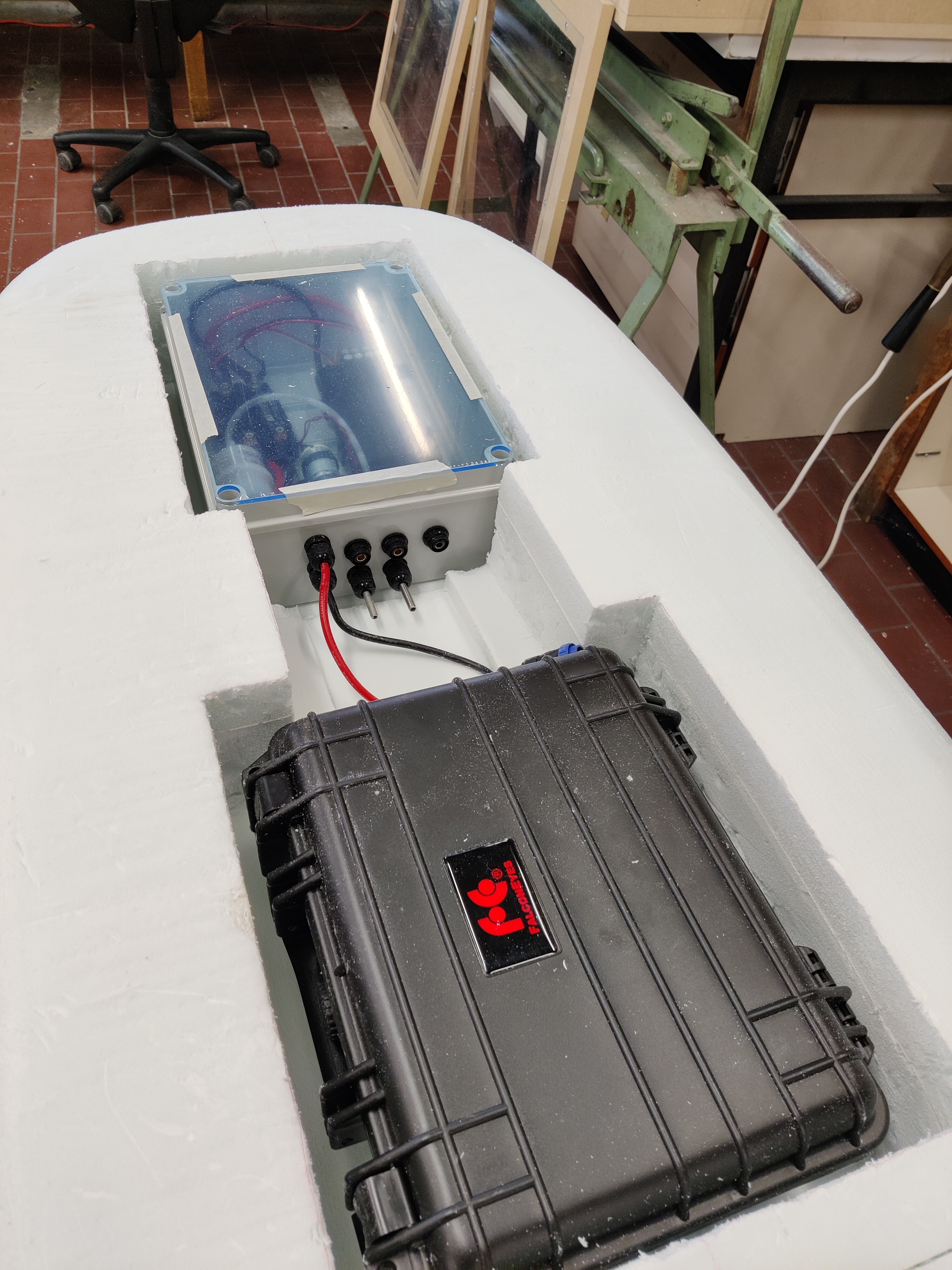
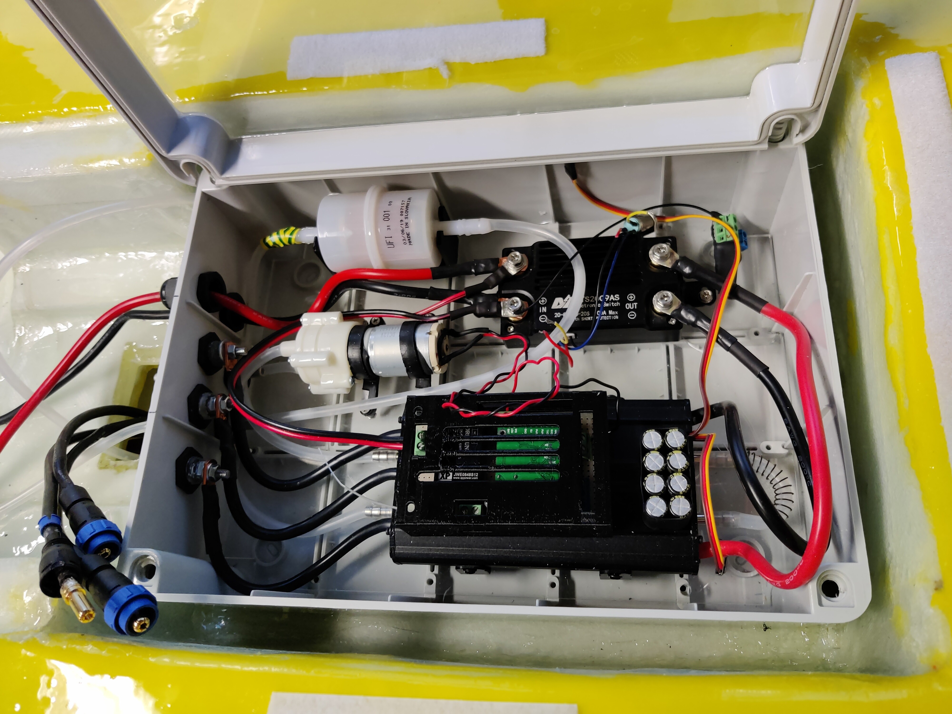
Considering to cut off the top of the grey box and glue a plexi plate on top instead to reduce the height to ~110mm instead of the now 135mm. This should allow me to thin the board slightly more to 14cm instead of the now planned 16cm without getting too thin underneath the boxes.
What do you think. Is it really a good idea to turn off the power supply under full load? I’ve thought about it and I think that the induction voltage from the motor can destroid the ESC. Do you believ that too?
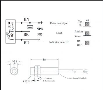
I send you the Data Sheet of the NJK-5002C Sensor. This Sensor is ready for use without any other Parts …
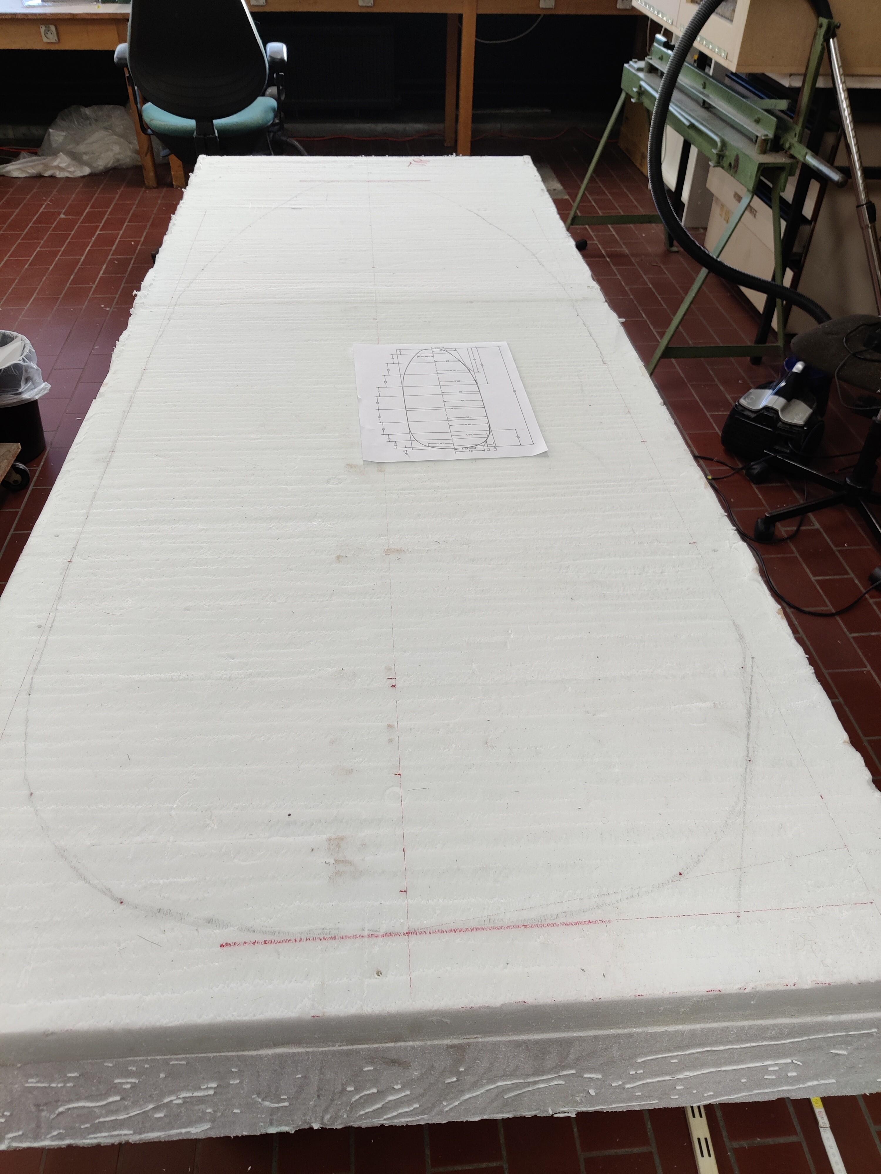
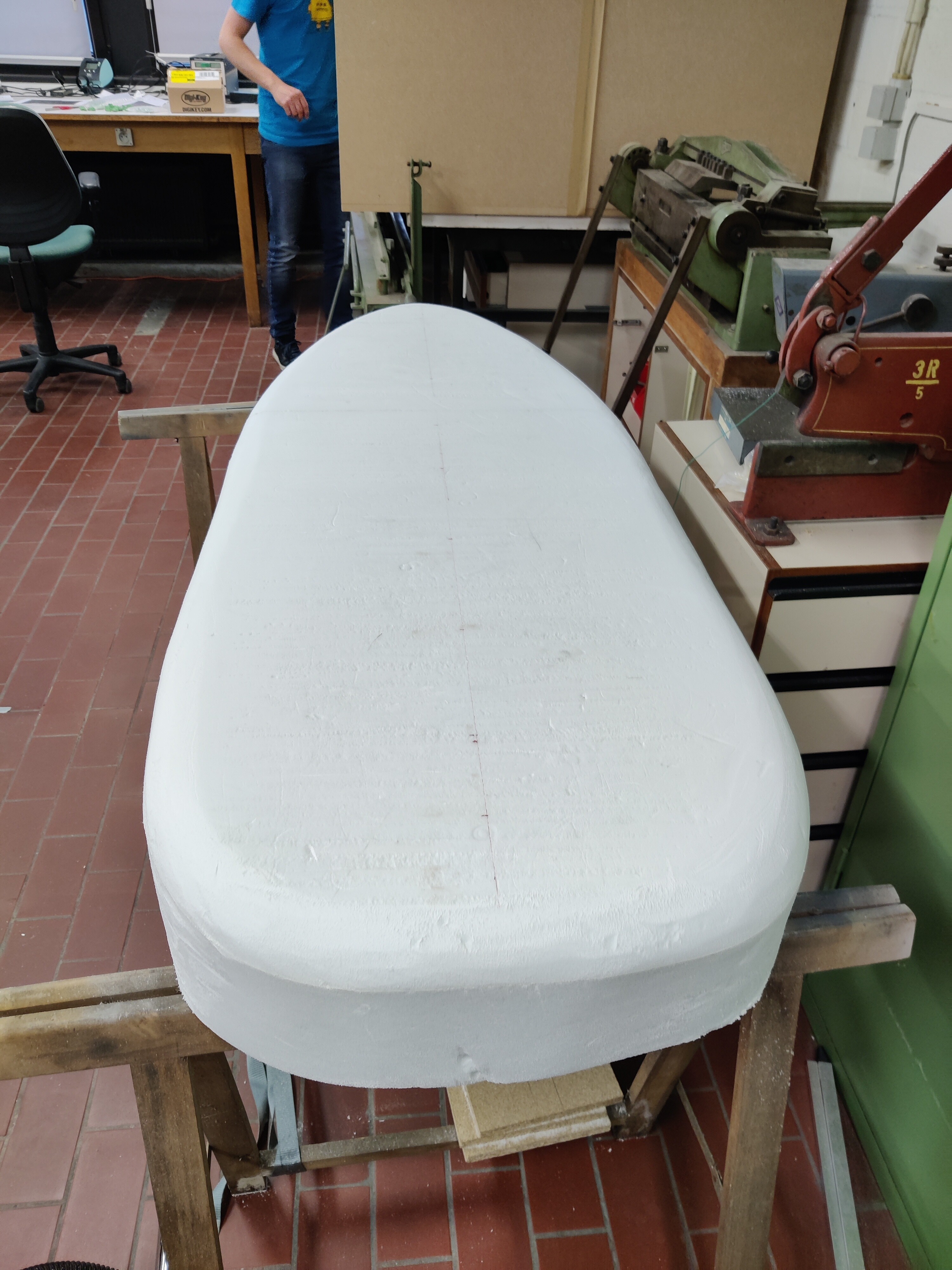
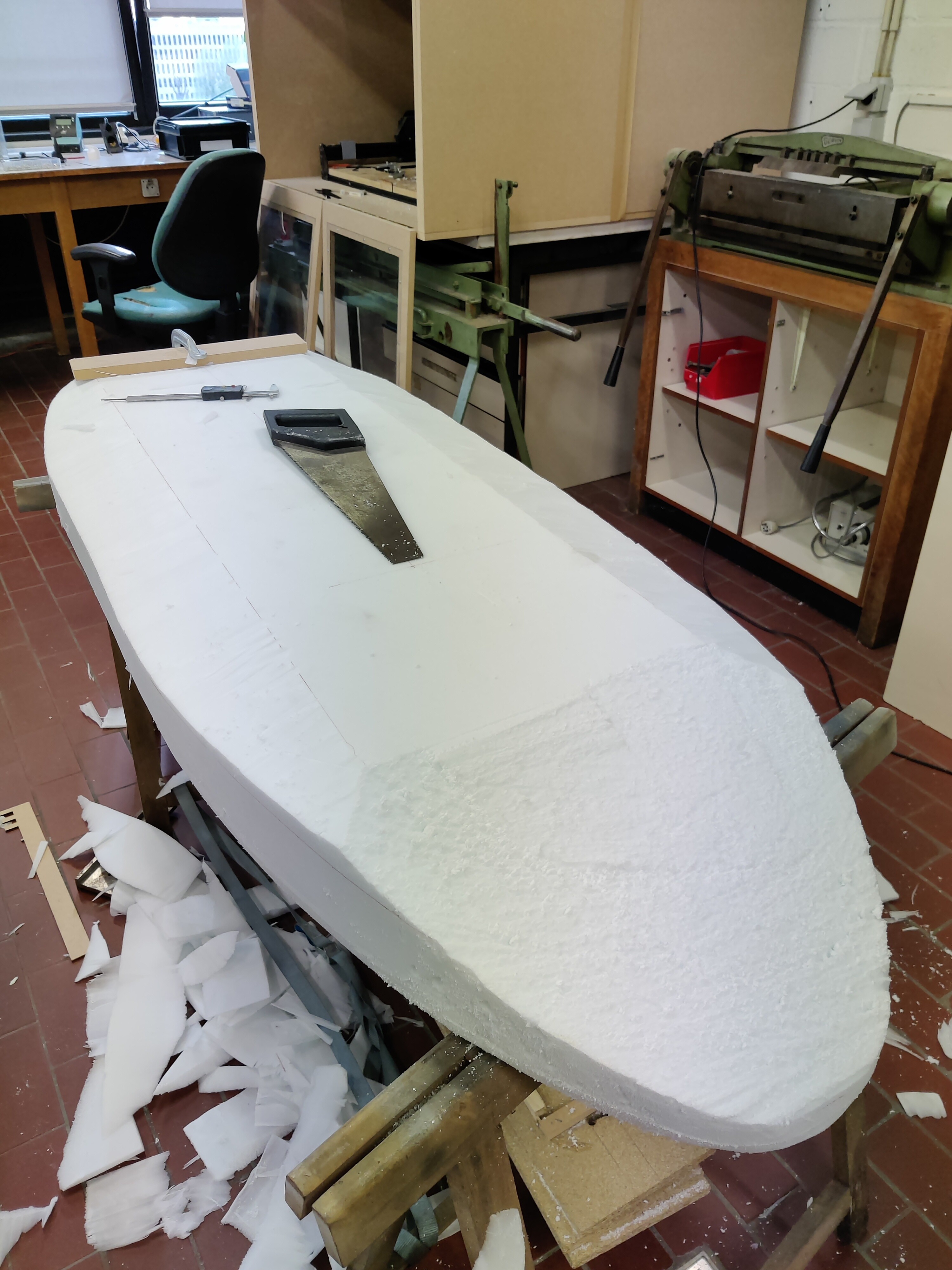
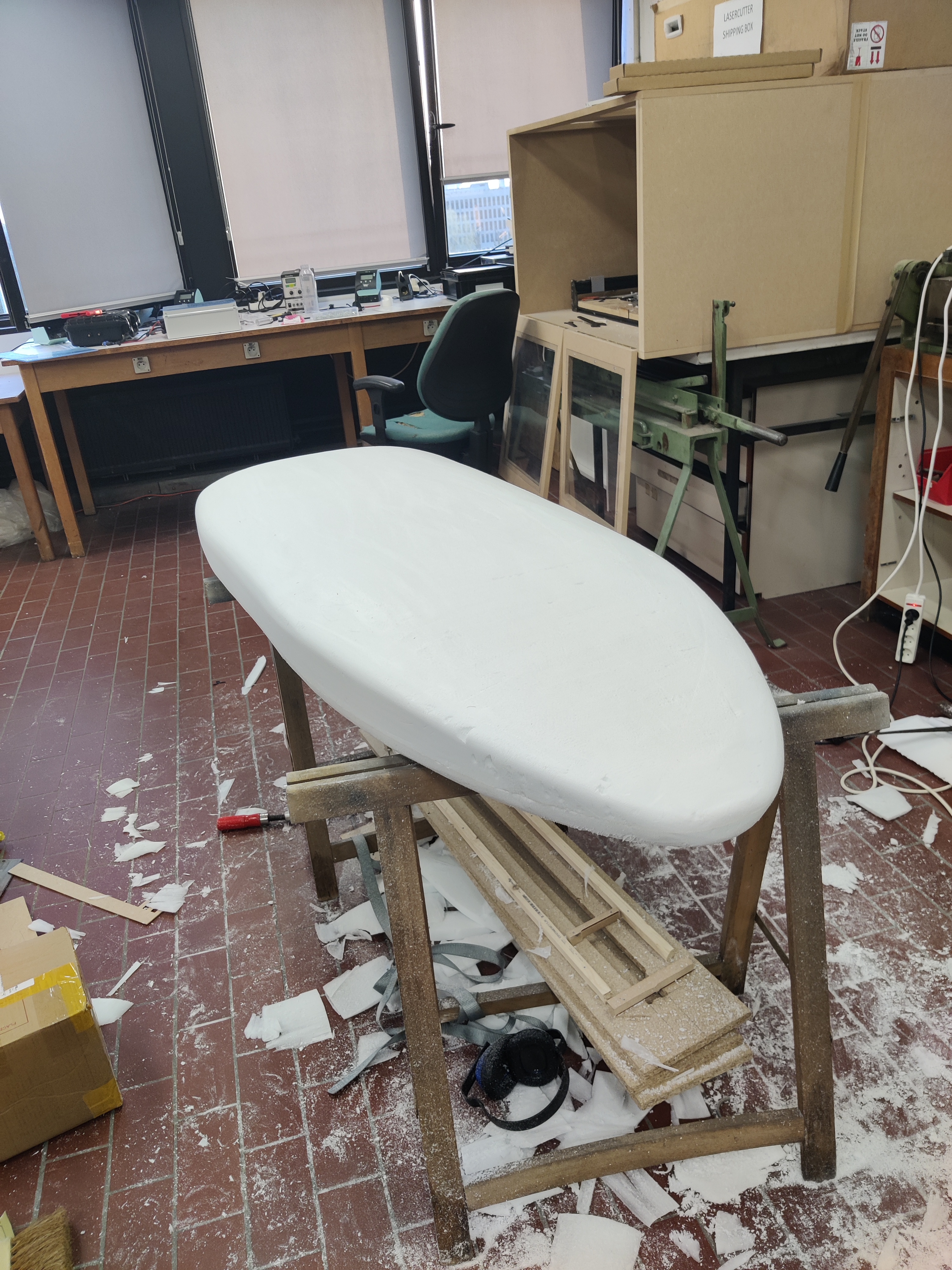
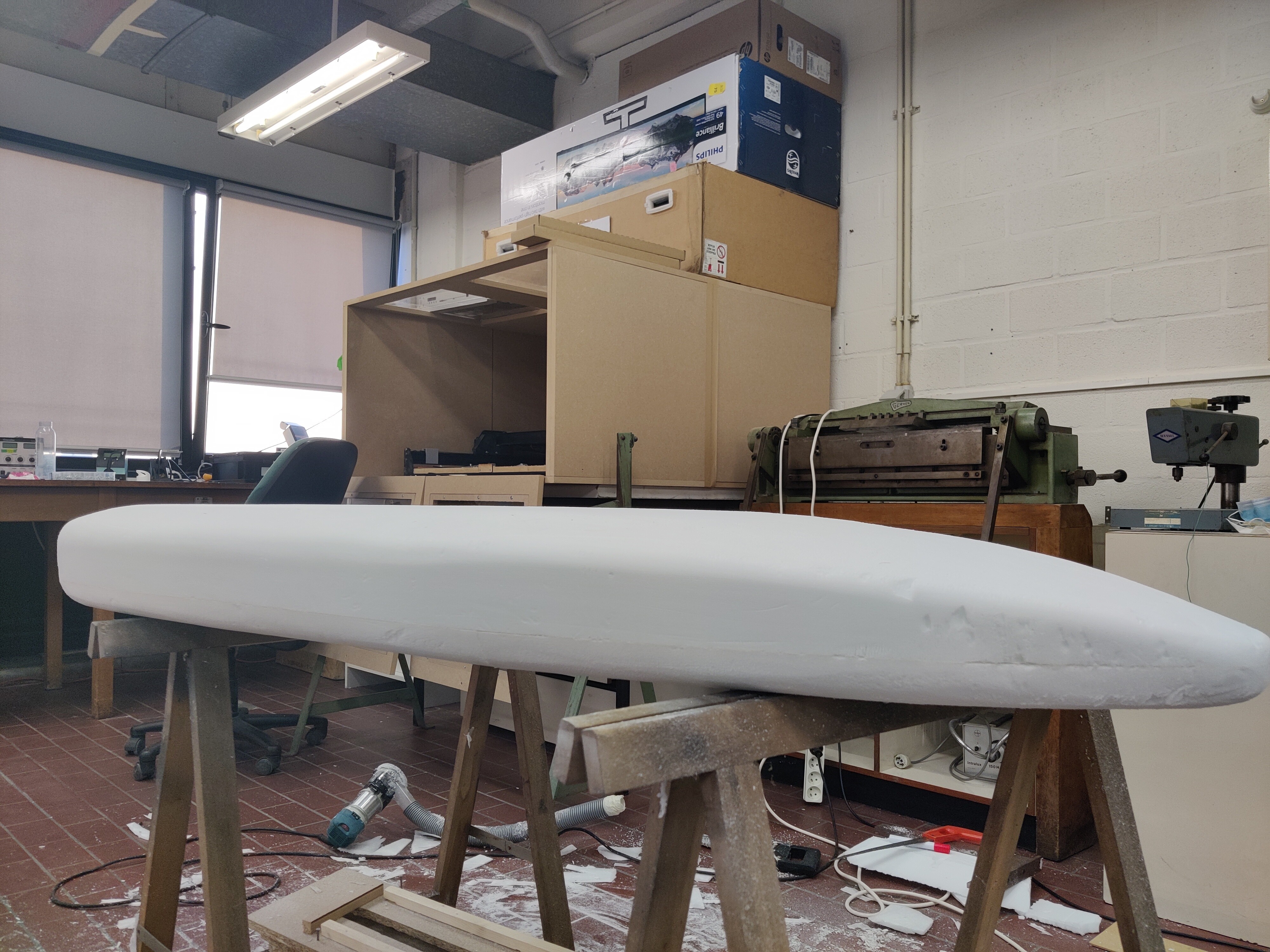
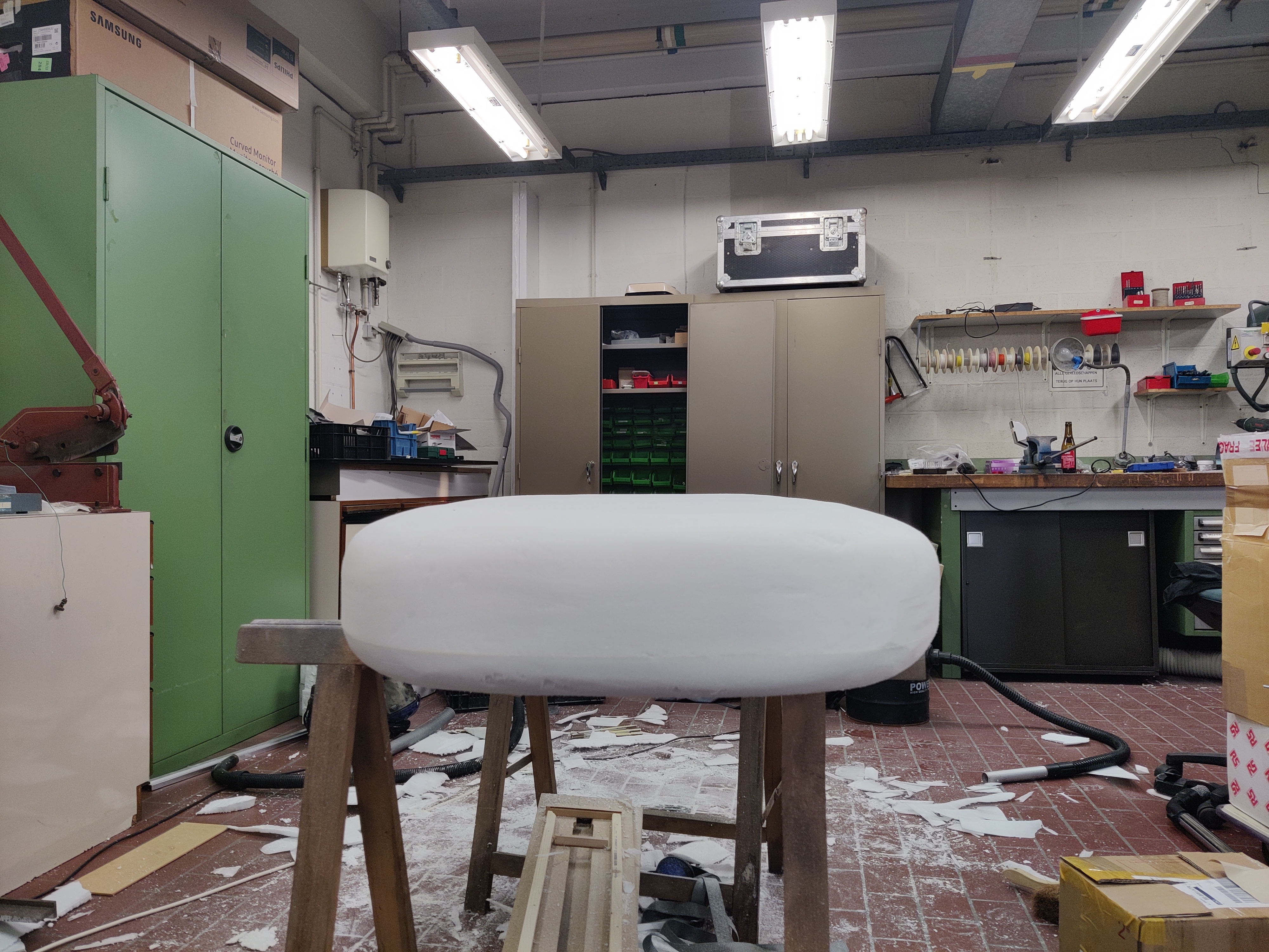
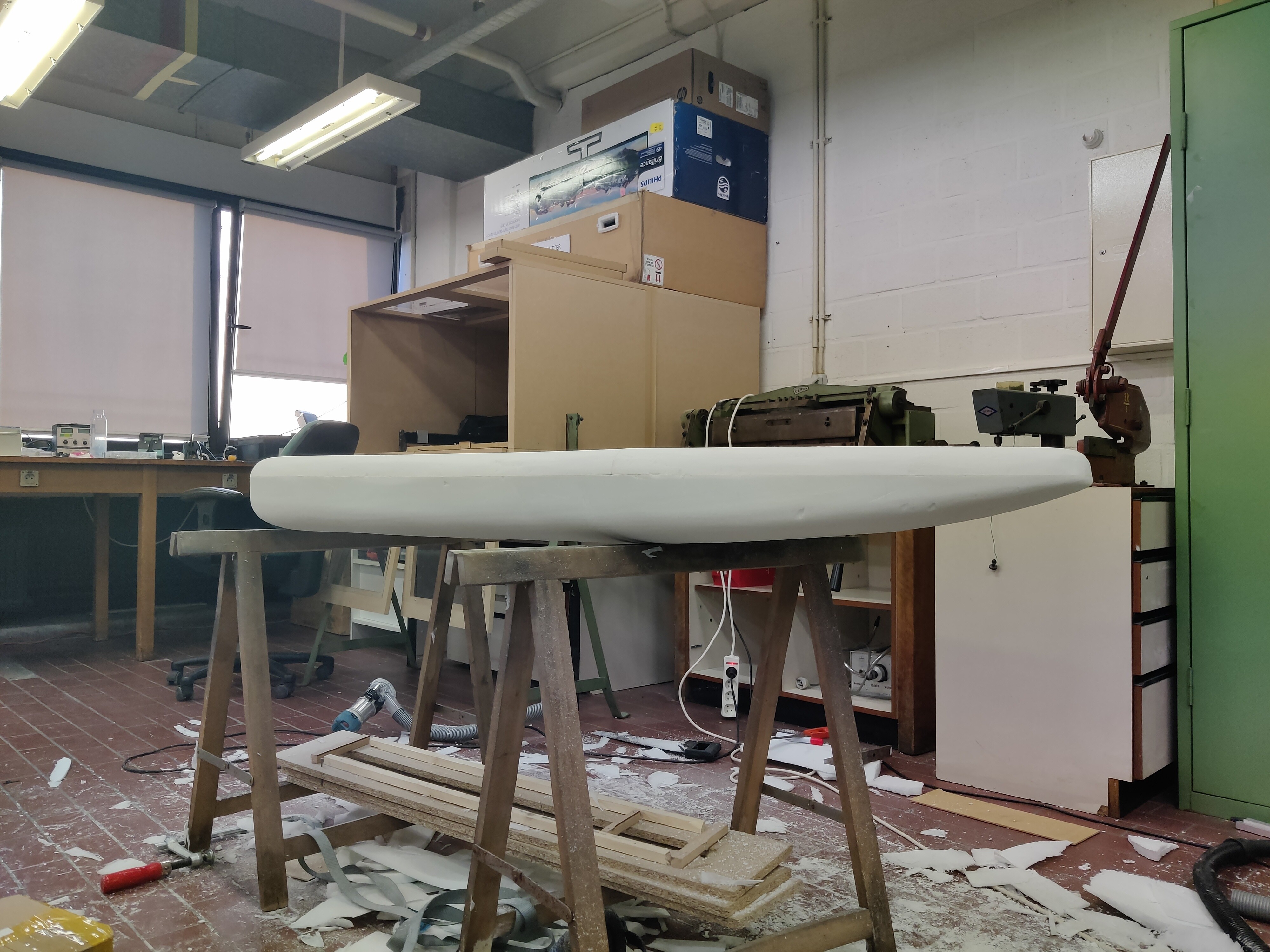
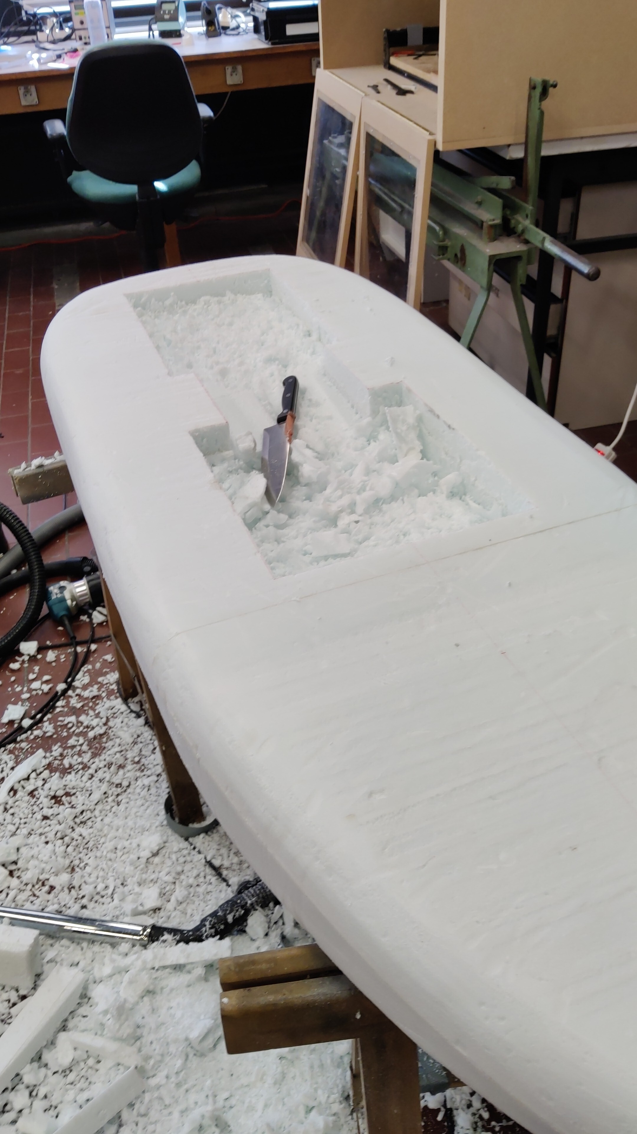
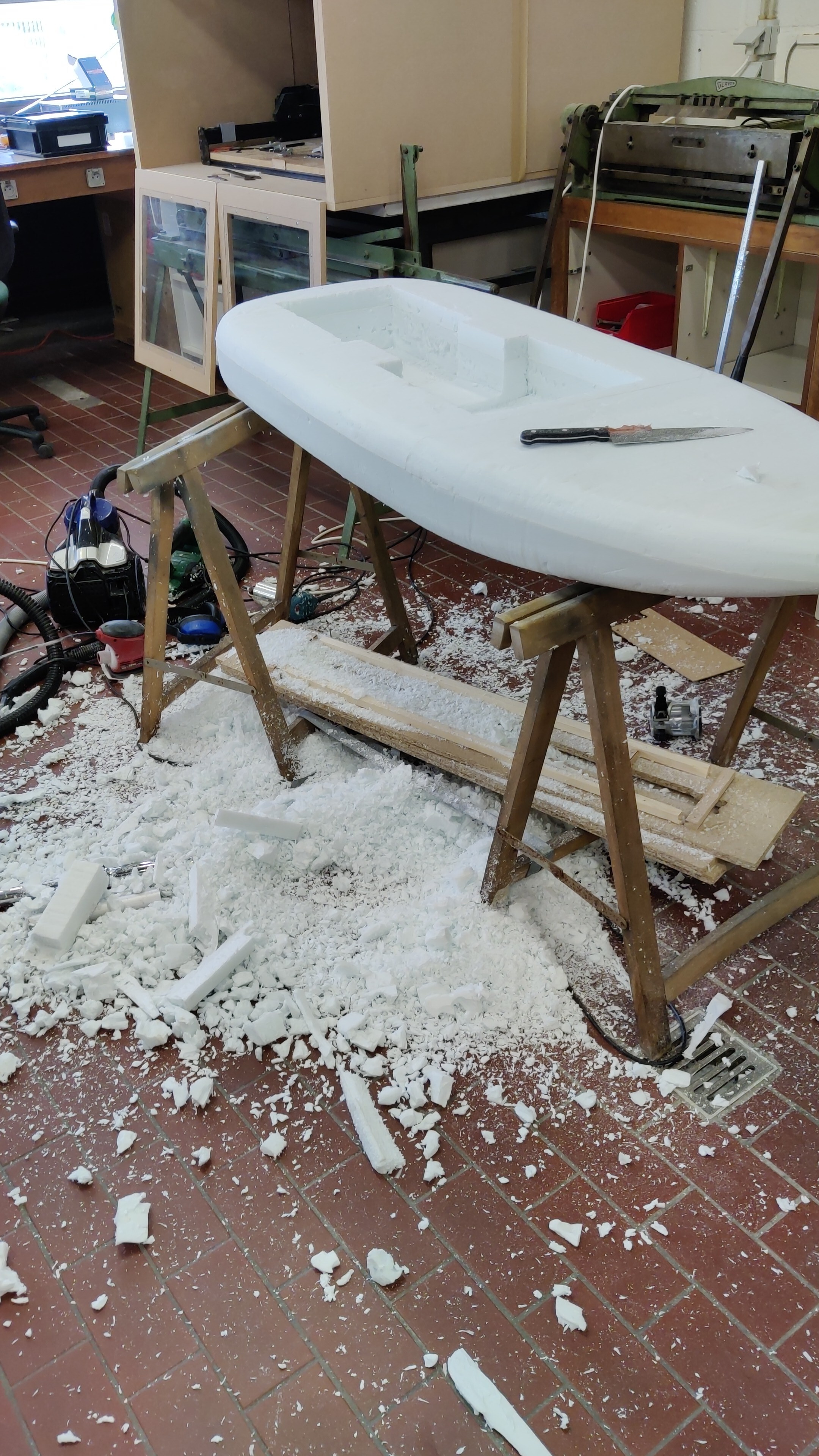
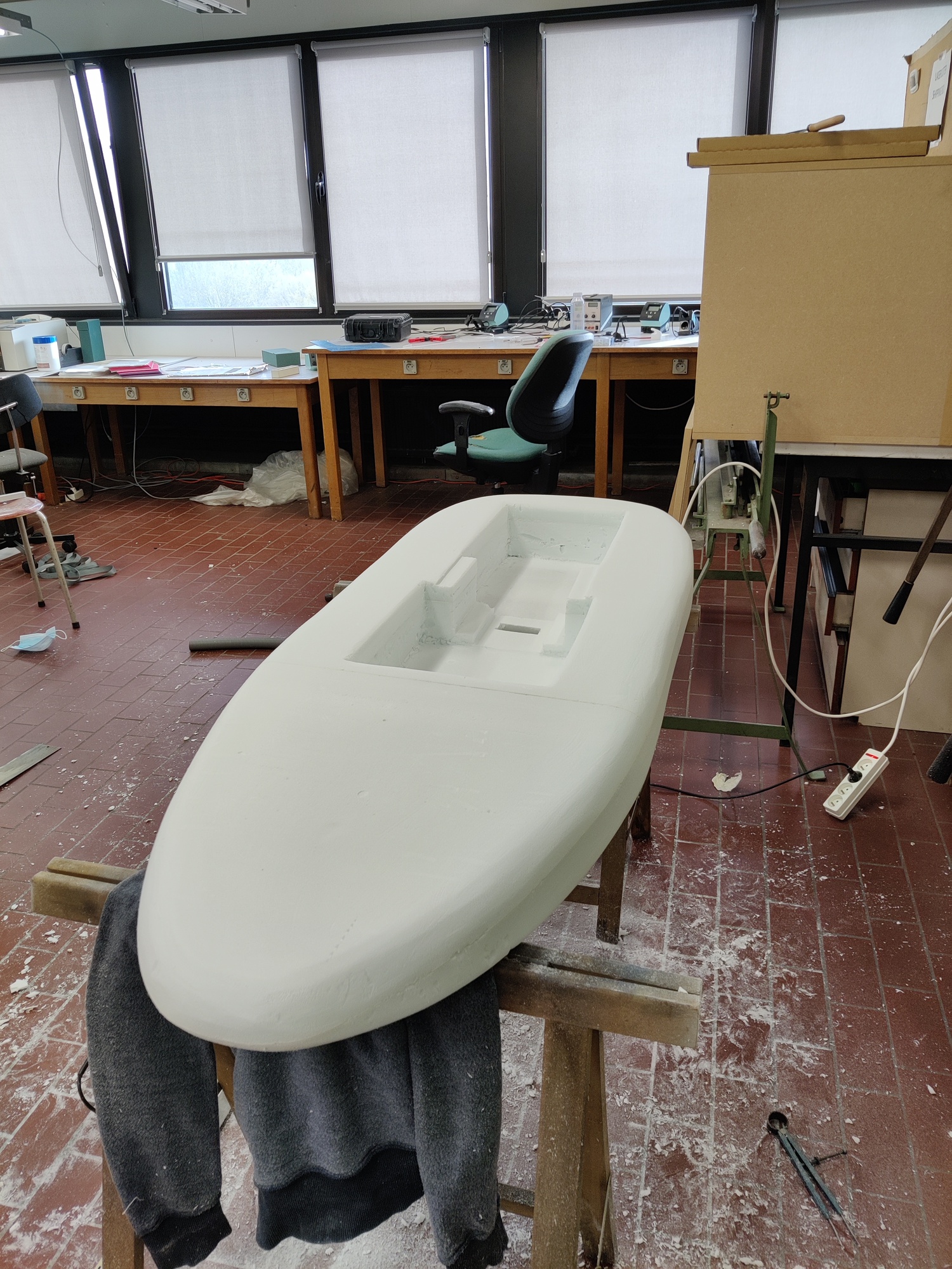
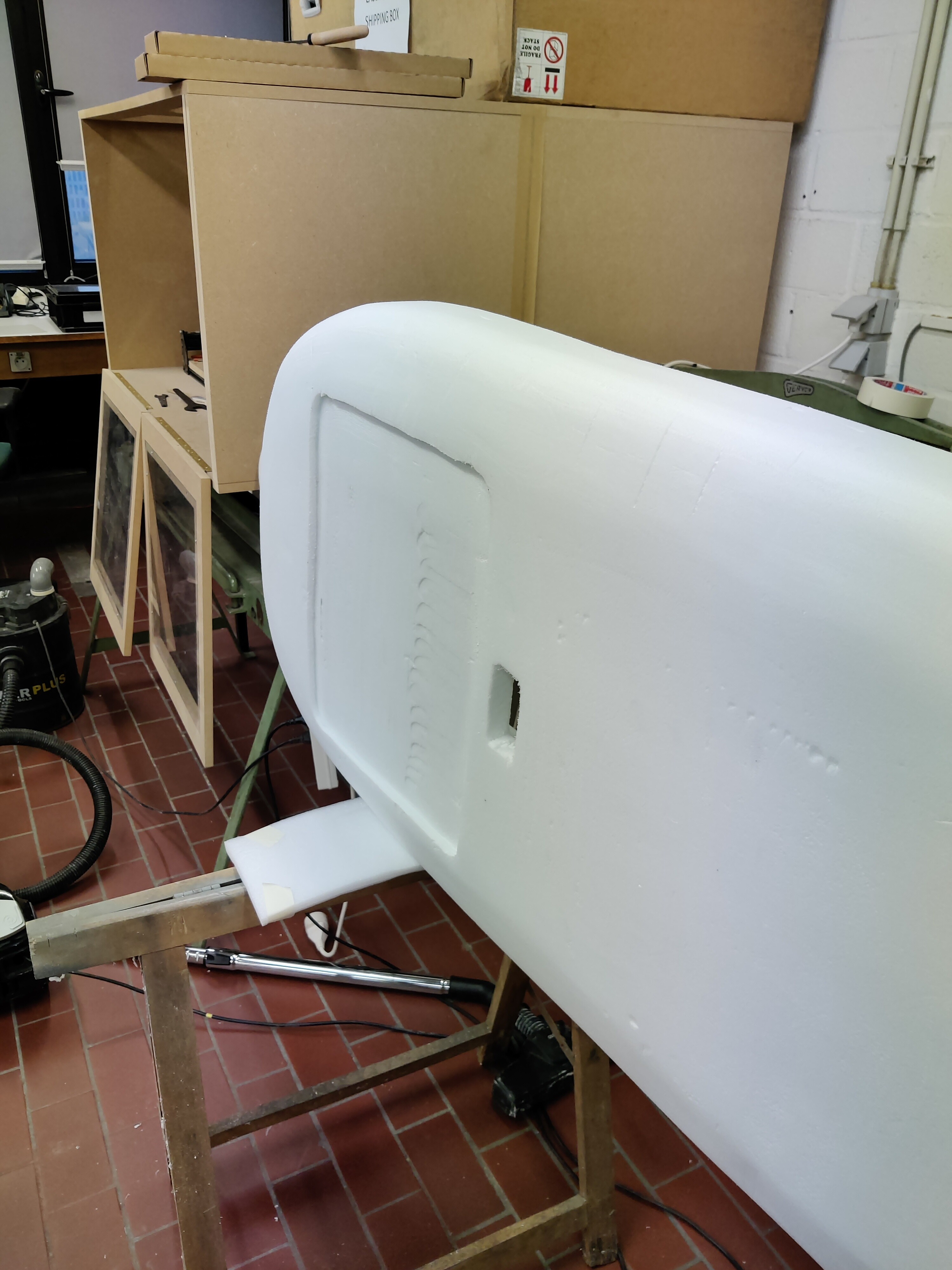
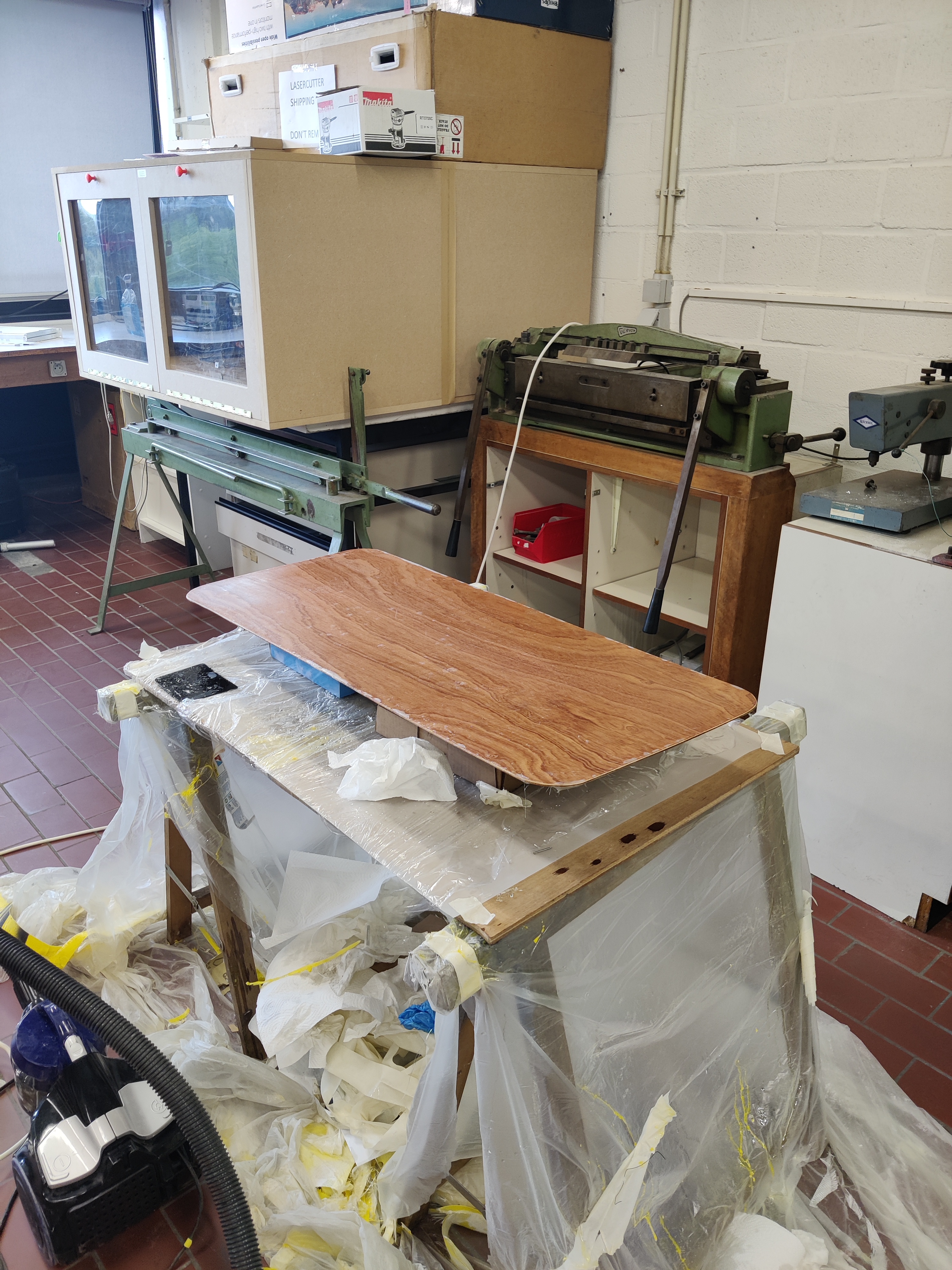
Shaping is mostly done. Left to do: mill the recesses for the electronics and batteries. Mill the cutout for the mast plate on the bottom side. Sand the whole thing and its ready for glassing.
I cut the top of the electronics box and lasercut a plexi plate to go over it. This allowed me to reduce the height to 12cm just like the black pelicase for the batteries instead of the original 13.5cm. This allowed me to reduce the thickness of the board to 15 cm without a lot of adverse effects.
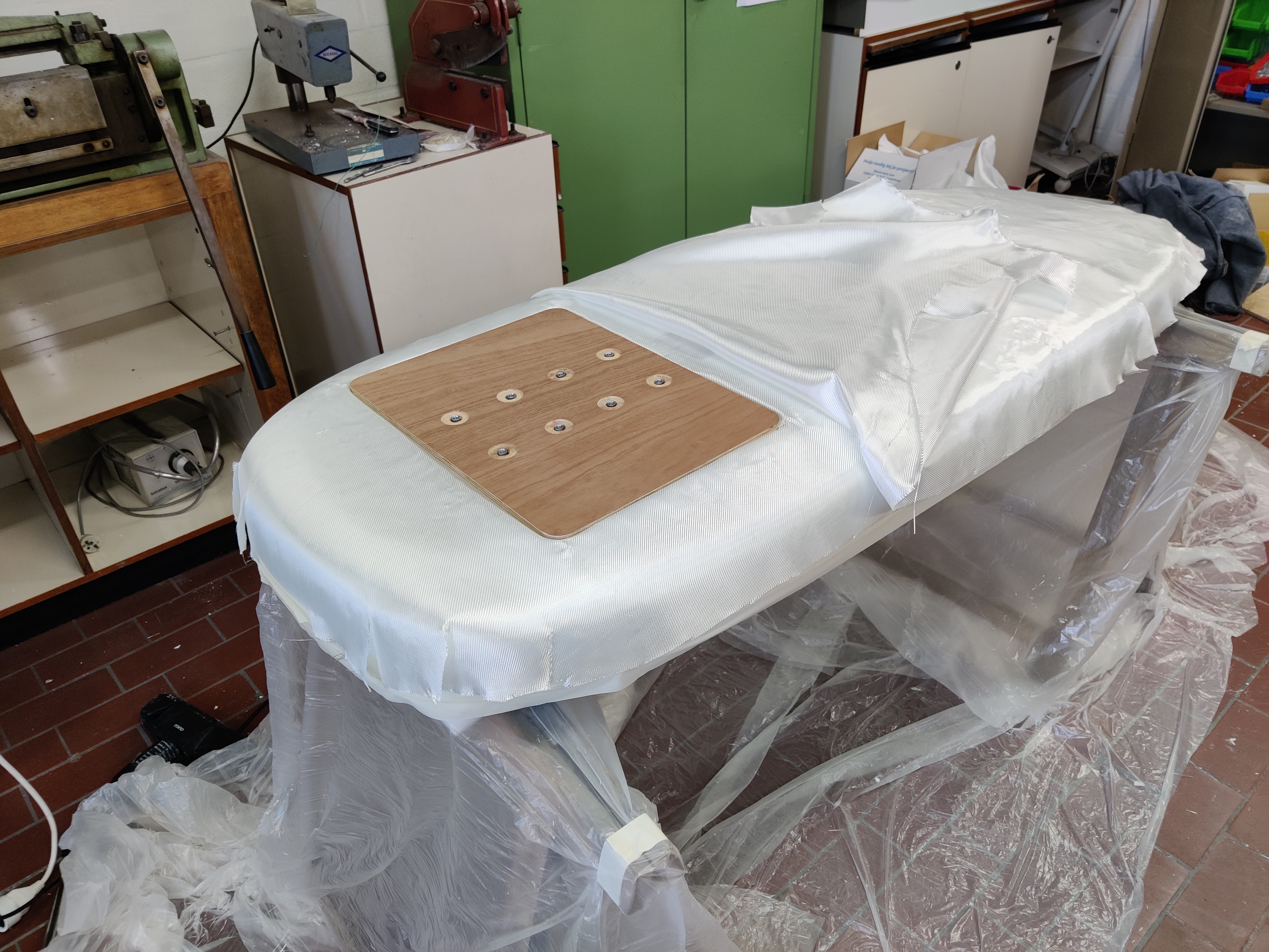
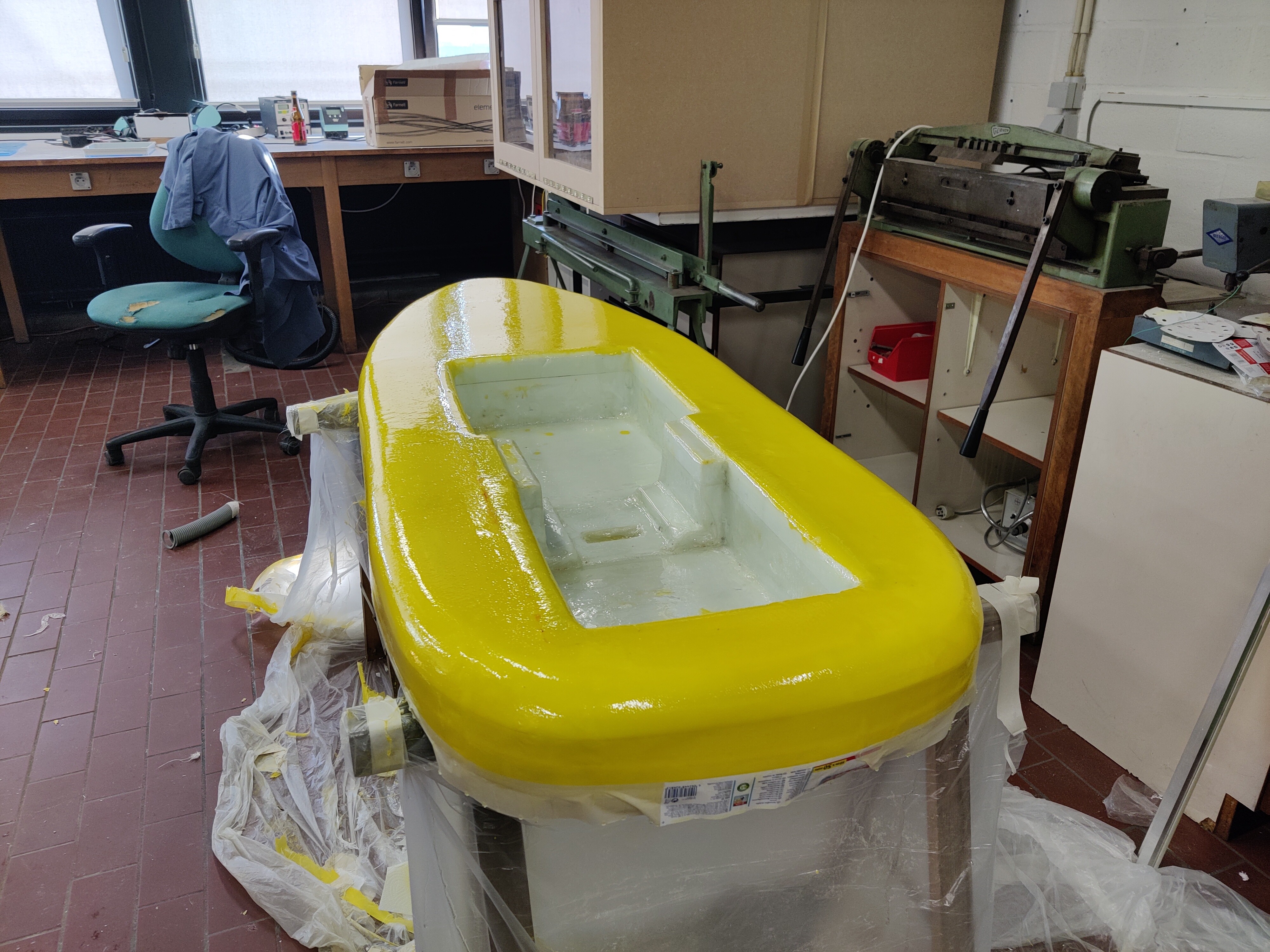
Routed a square where the mounting plate for the mast will go. Bottom side will be glassed with 220g fiberglass mat first, then the plate will be inserted, and another layer of 220g for sturdiness.
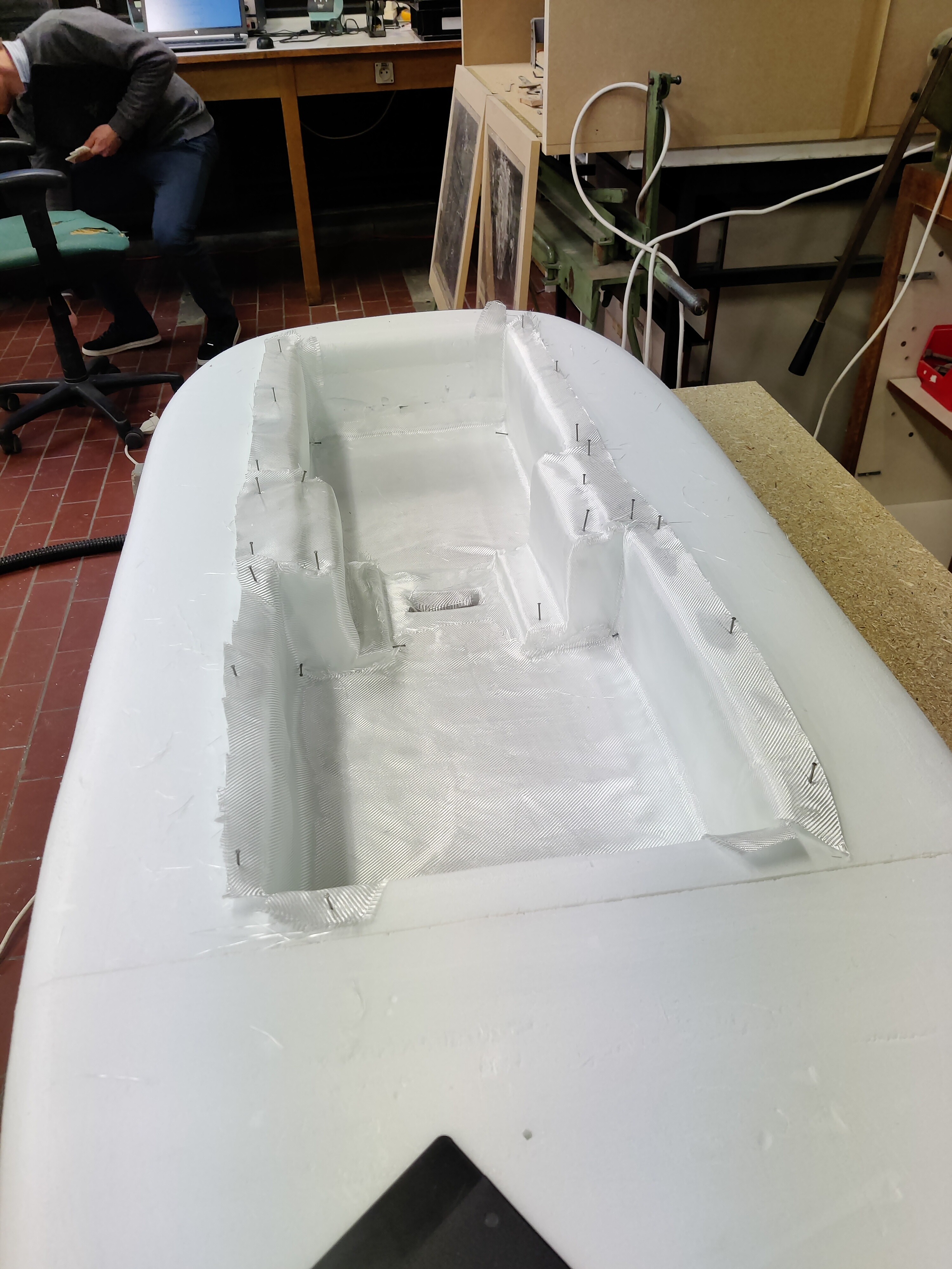
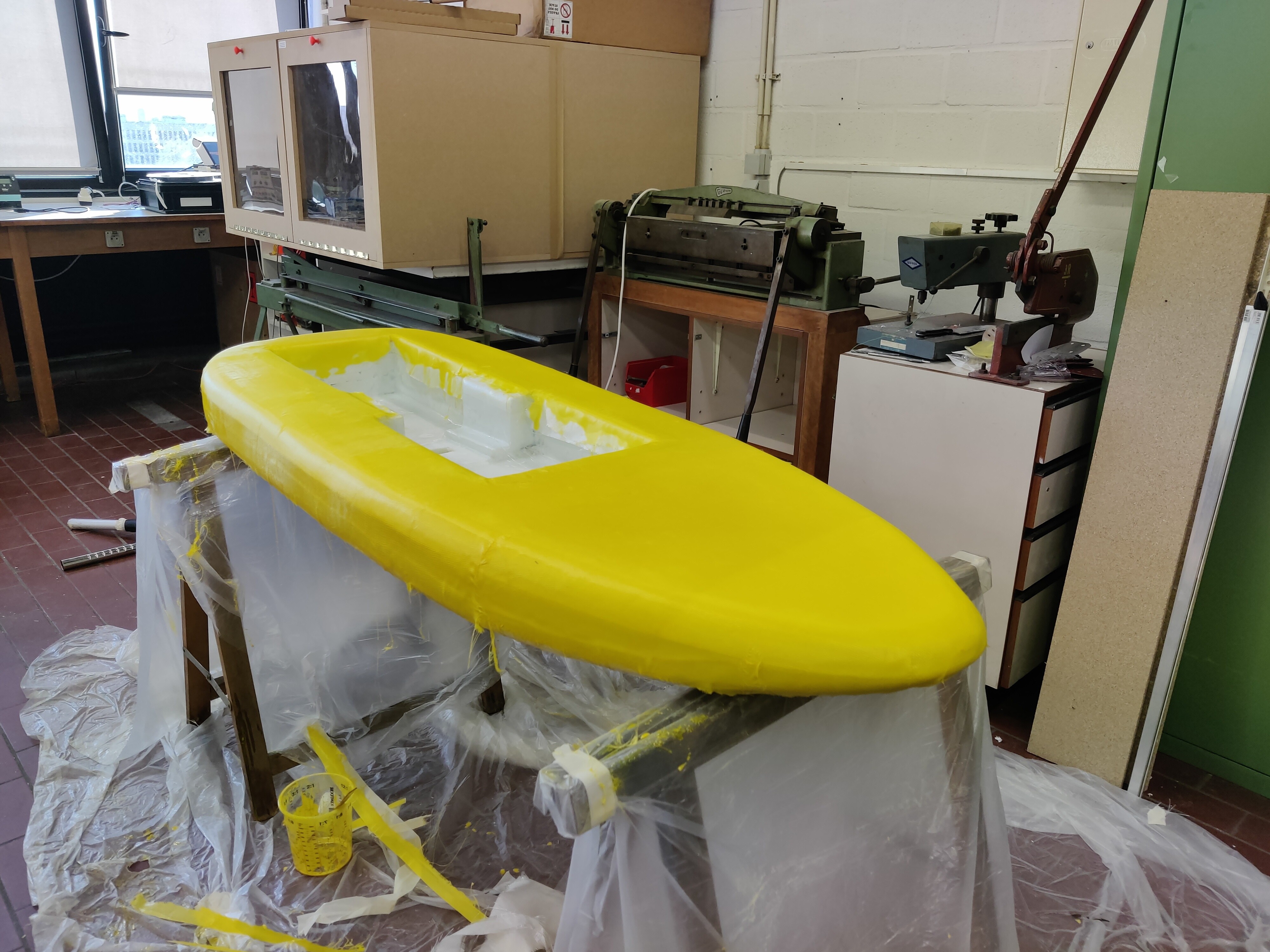
Mistakes were made… not filling up the cavities in the foam (on the sidewalls of the cutout) was a bad move… I think adhesion to the walls will be limited there, but now its too late for that. Strength wise this is probably far from ideal, but the top and bottom with 2x220g should well compensate for that…
All the small corners and edges will probably result in bad seals. A lot of small gaps were already spotted in places where the mat was cut to remove excess material. So a lot of sanding and a second layer with 110g will be necessary to seal everything well. Any suggestions on how to get a good seal on all the small corners and edges?
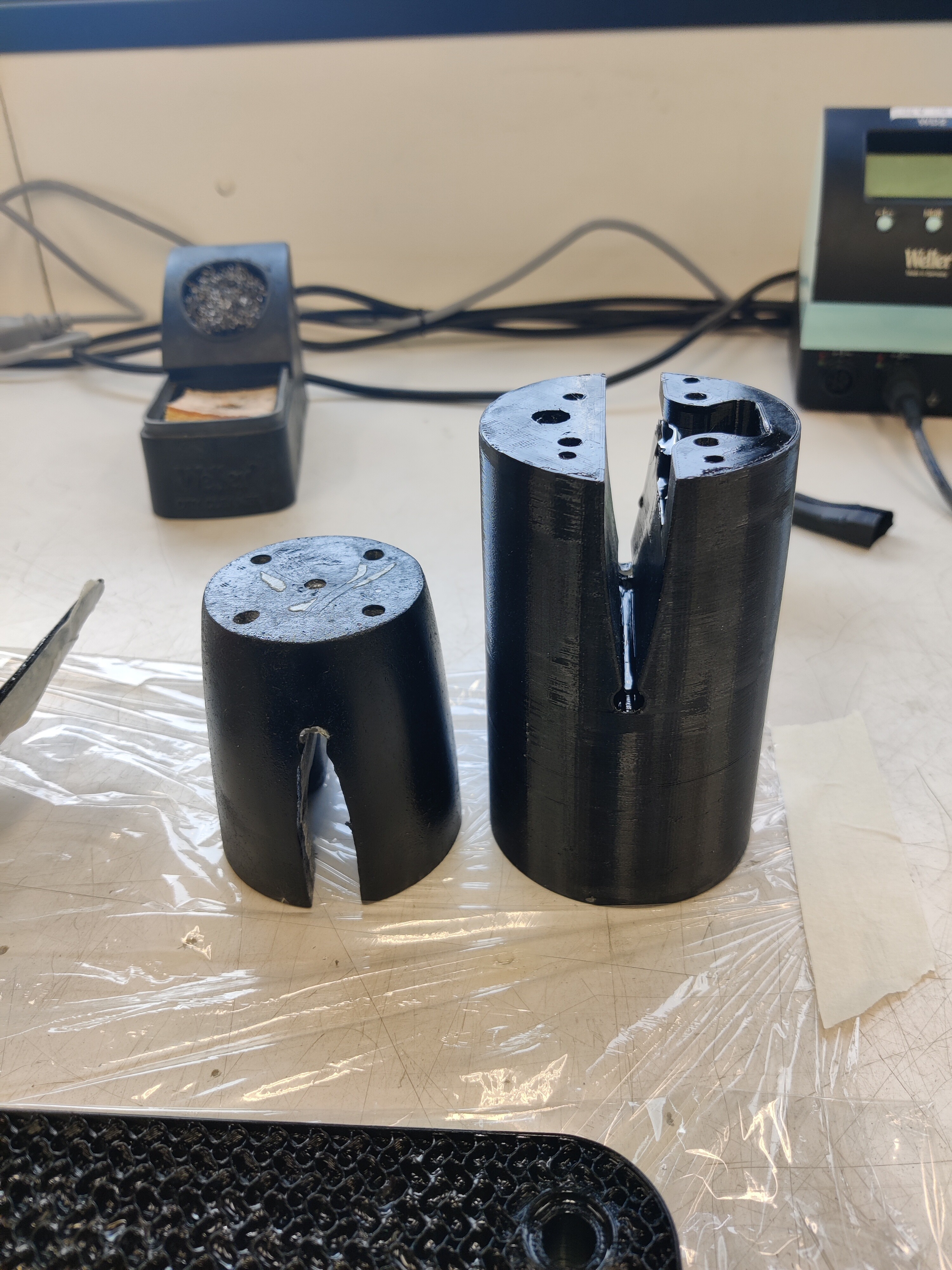
Printed a small enclosure to put the pcb with the receiver away cleanly. Extrusion temperatures were a bit off for this large layer height so the print quality is not great.
I suggest filling the inside corners with a fillet, rounded tongue supressor or handle to make them smooth. Use a microballon/ fairing mix that is easy to sand. Same on the outside corners. You already have the strength. Now you are looking for smooth and a seal. You can add
‘barrier coat’ additive from more waterproofing. Sand earl while it is not to hard but wear a respirator for sure… I was wondering if a big trashbag filled with warm water could push the cloth and epoxy into the corners. I might try that if I do an 'inside shape. Also thinking that rounding the corners and starting with a thin 4oz layer of glass might help. The little bubble voids are such a drag. Your build is looking great! Good luck
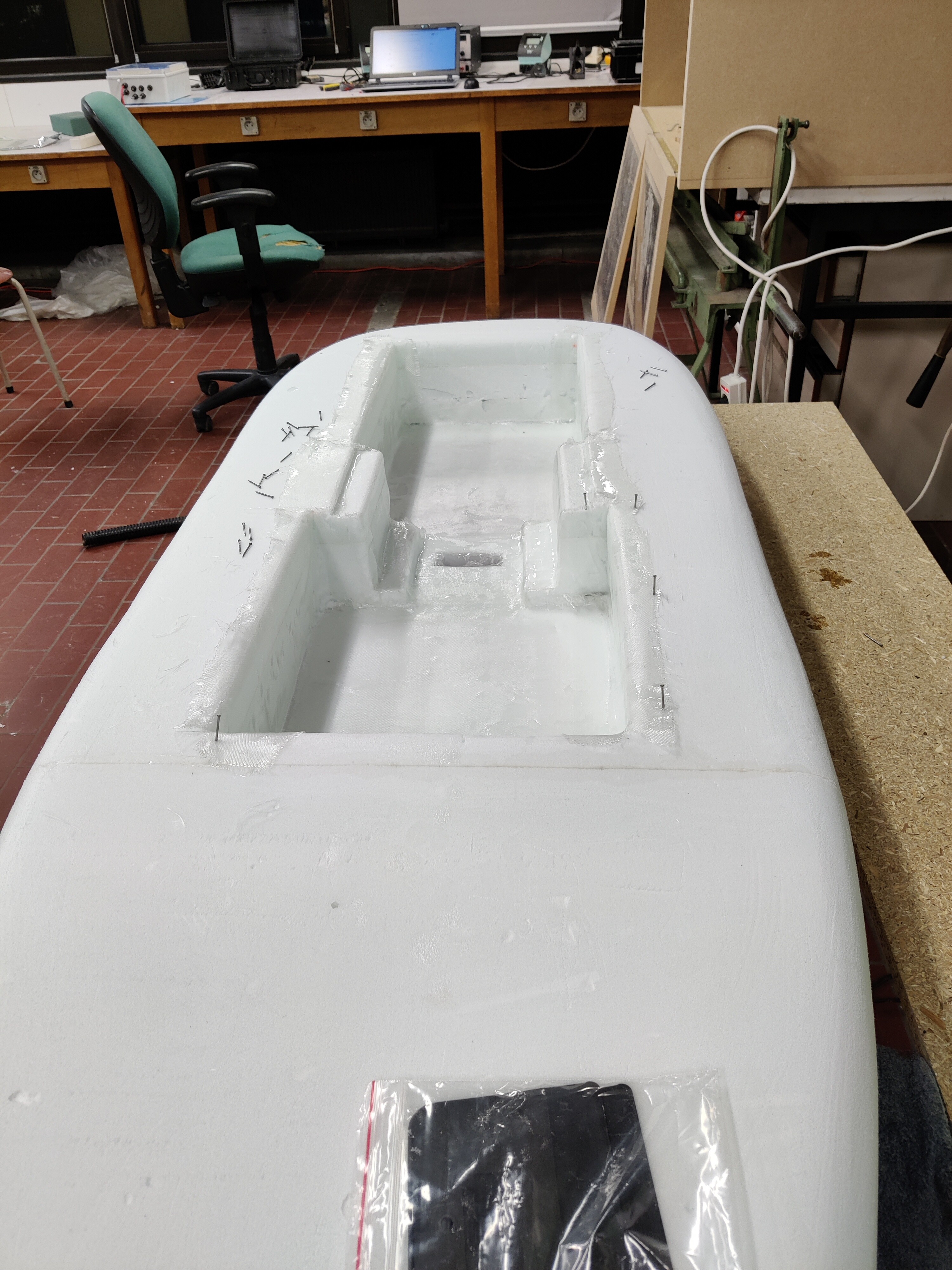
I shouldve filled the voids in the walls with microballoon based filler, and created fillets… Hindsight is 20/20. But removing the current layer is going to give worse result than leaving it I recon. So another layer of glass will hopefully help me get everything watertight especially. If I make patches to overlay on the current gaps, and then another sealing coat without glass it will hopefully be sufficient. Top and bottom are going to be easier since these have less corners and more fillets.
Finishing for that part is not that crucial since it will be covered by a plate anyways. but it should not allow water ingress into the core.
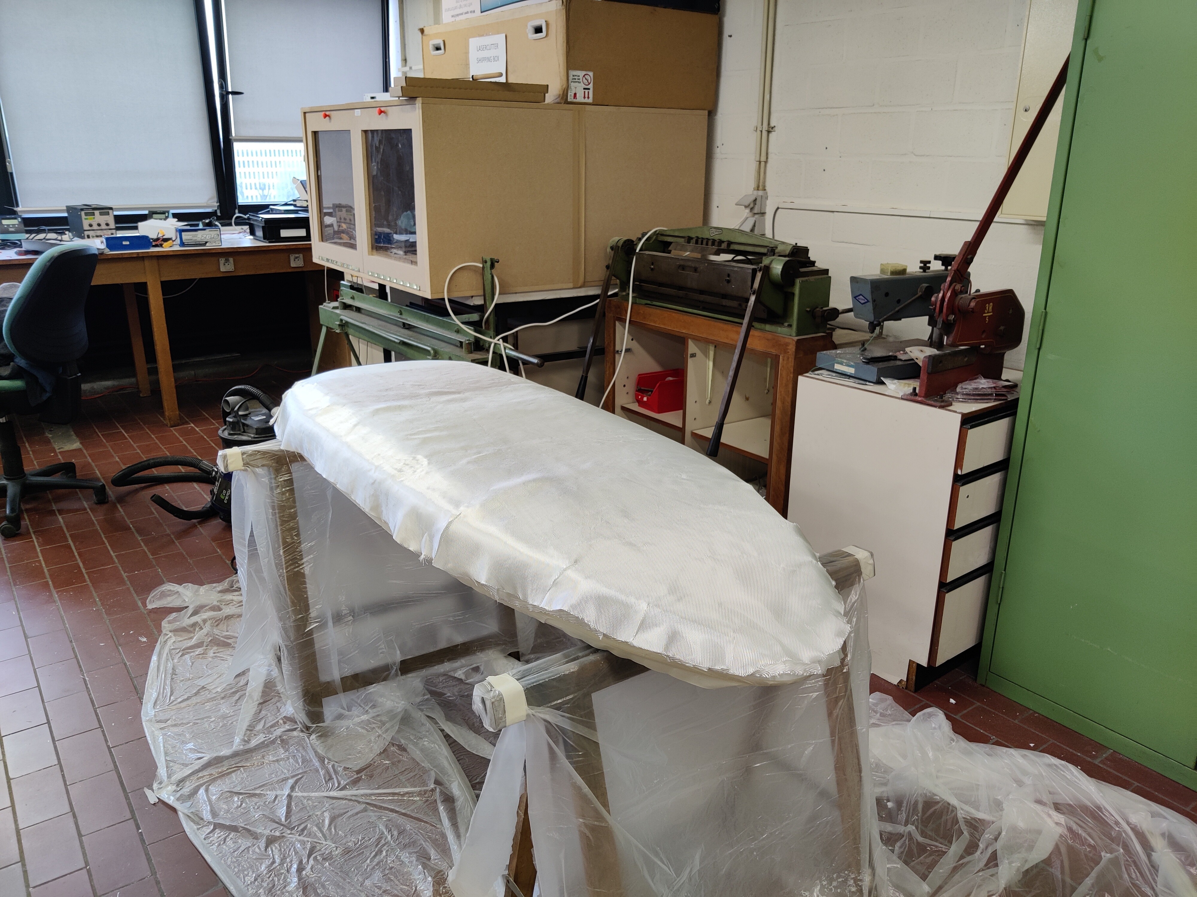
More glassing. doing the bottom layer first before continuing with the rest of the glassing
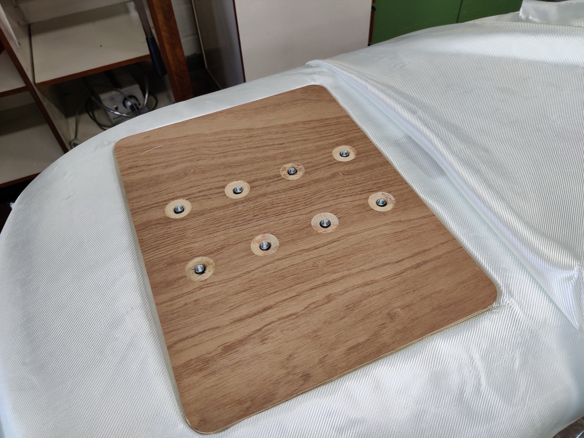
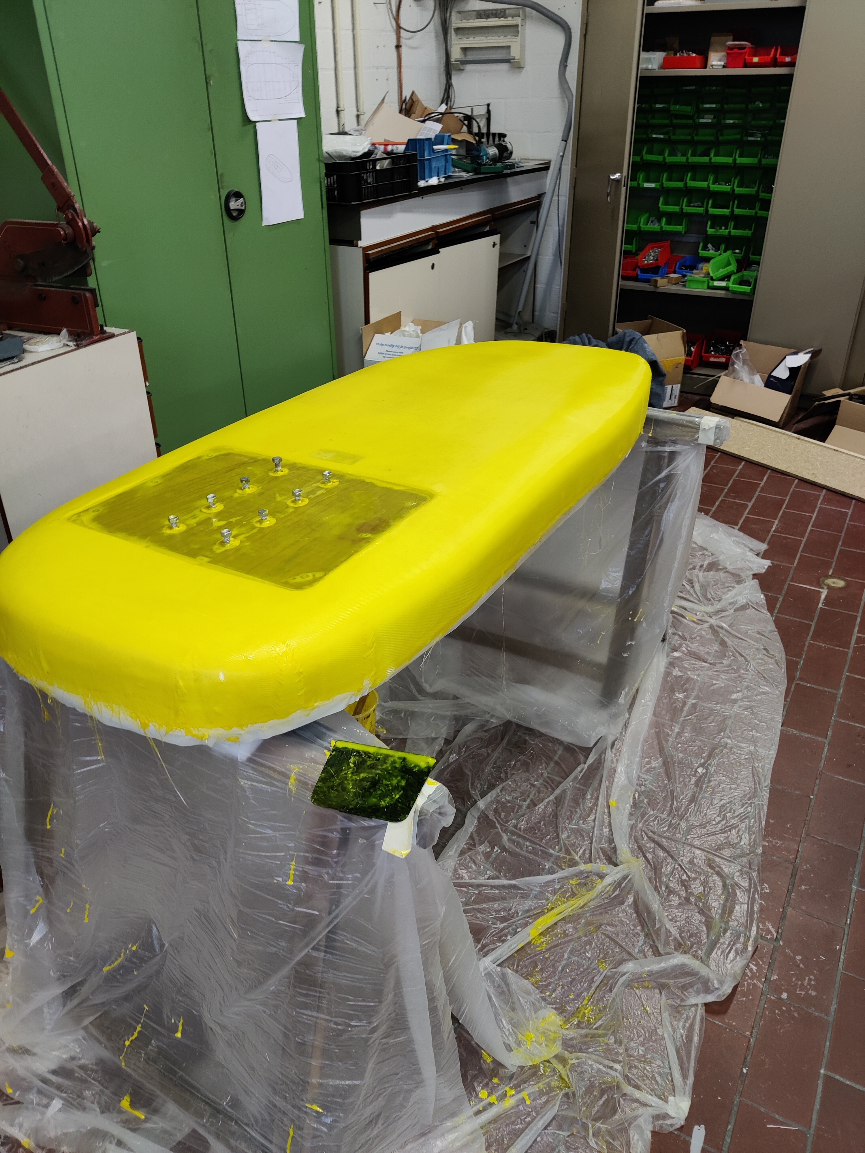
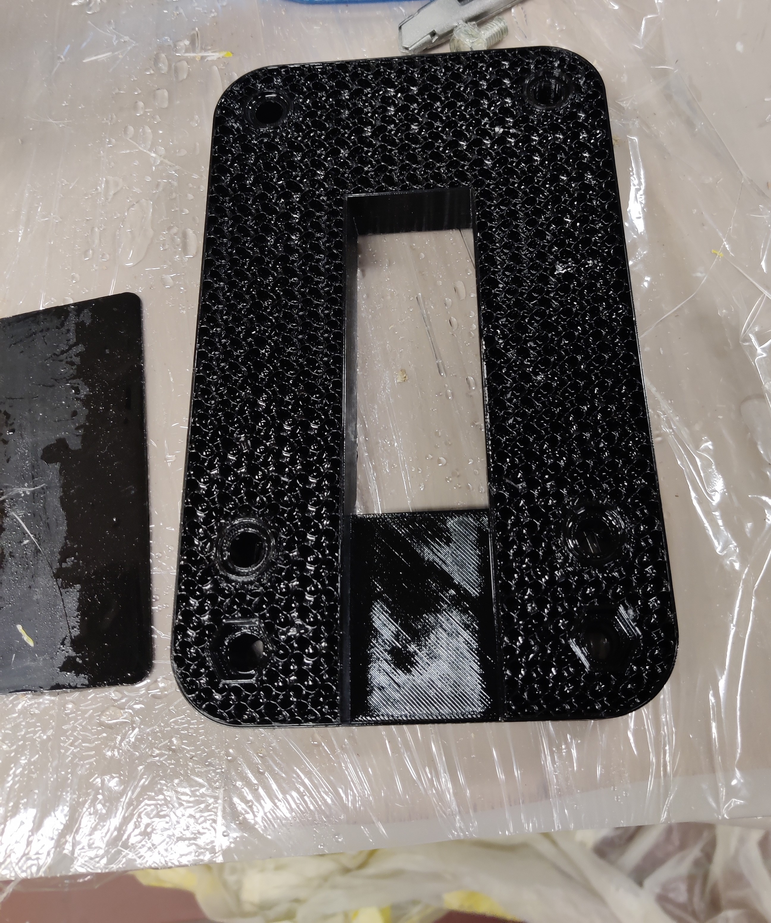
Plate for the mast mounting in between two layers of 220g/m2. CNCed some 8mm plywood for the mounting of the mast. Made 8 mounting points so some slight adjustment in mast position would be possible.
Screwed in some waxed bolts into the mounting holes to prevent epoxy from seeping in. Only realized afterwards that 1 layer of fiberglass over the mounting plate might be a bit lacking. Even if it is epoxied in and has a few long screws into the foam. Ill probably add another layer but only locally to strengthen the bond there.
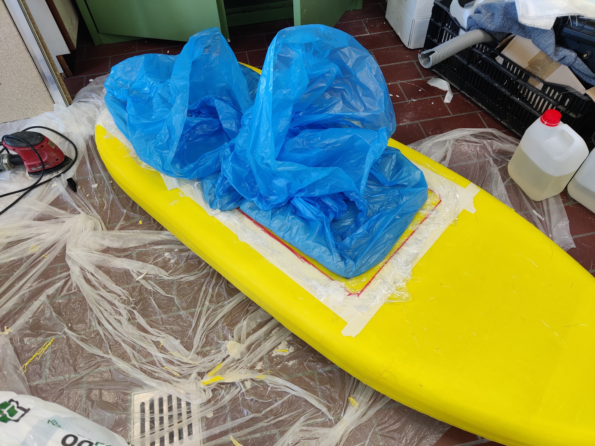
Small fail there. I put some layers of plastic foil to separate the bags from the resin. But here and there It got stuck in due to the hardened resin. A bit of a pain to get out.
Reinforced the bottom where the mounting plate is with another layer of fiberglass after the facts. And injected epoxy into the voids next to the bolt holes.[no picture]
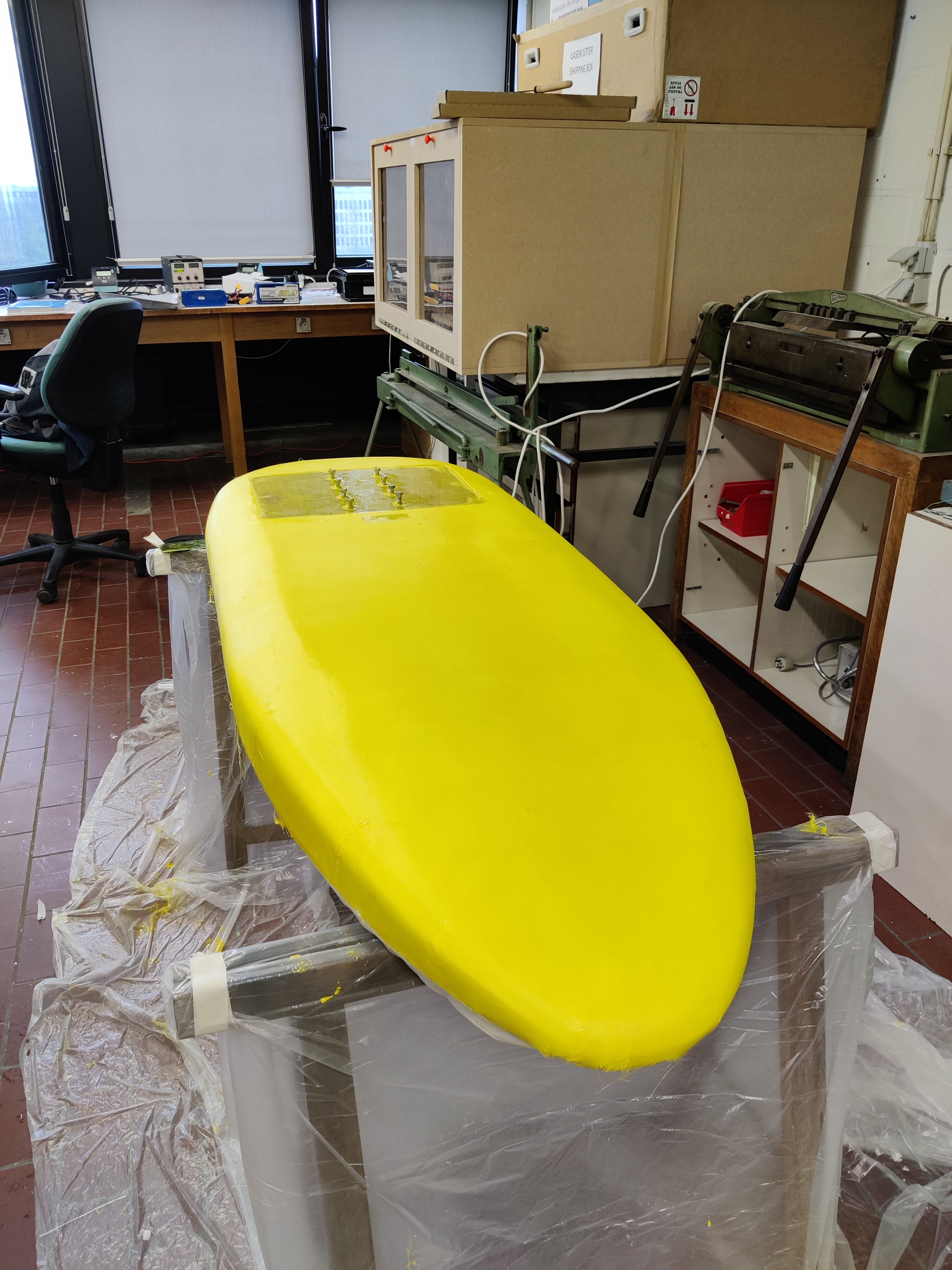
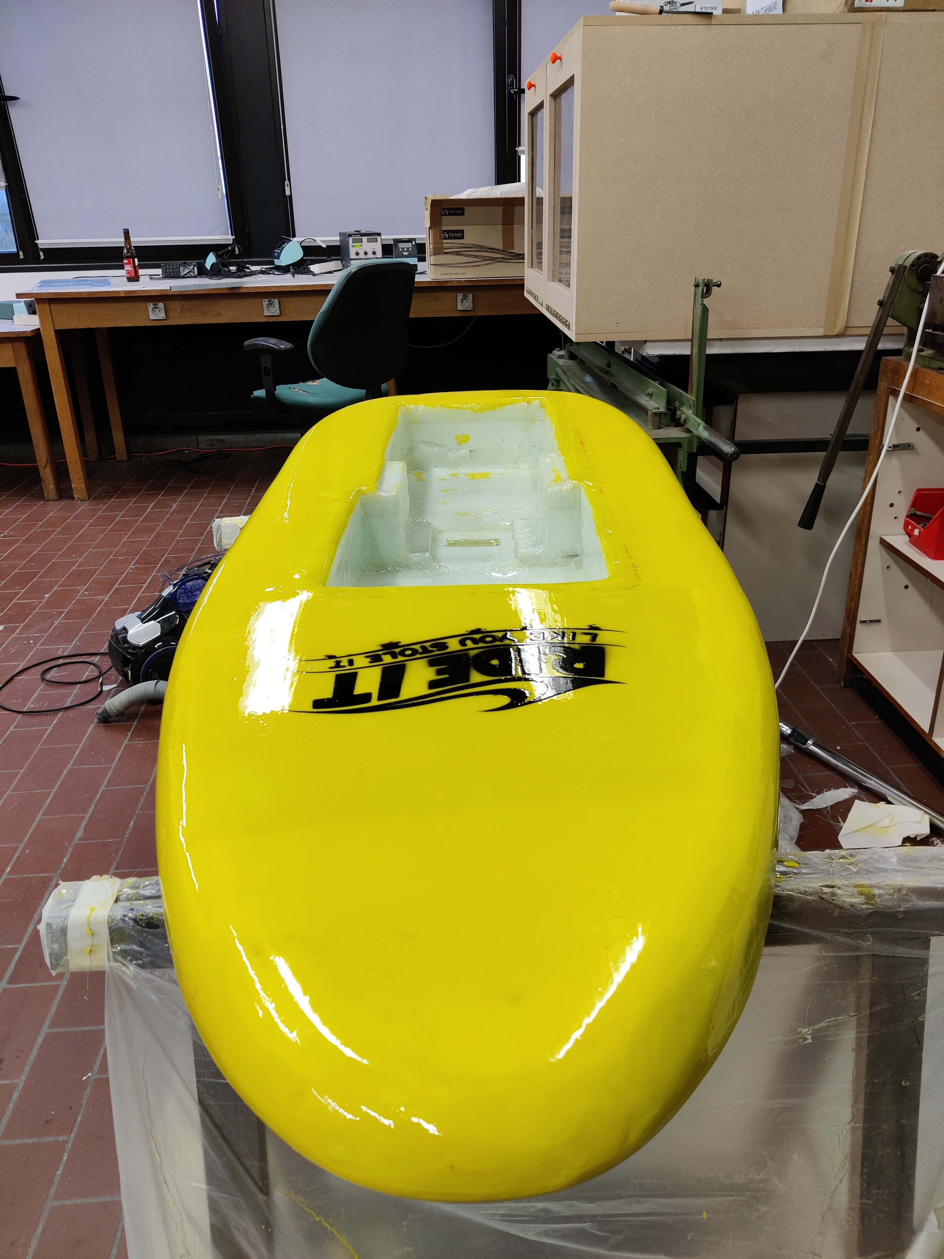
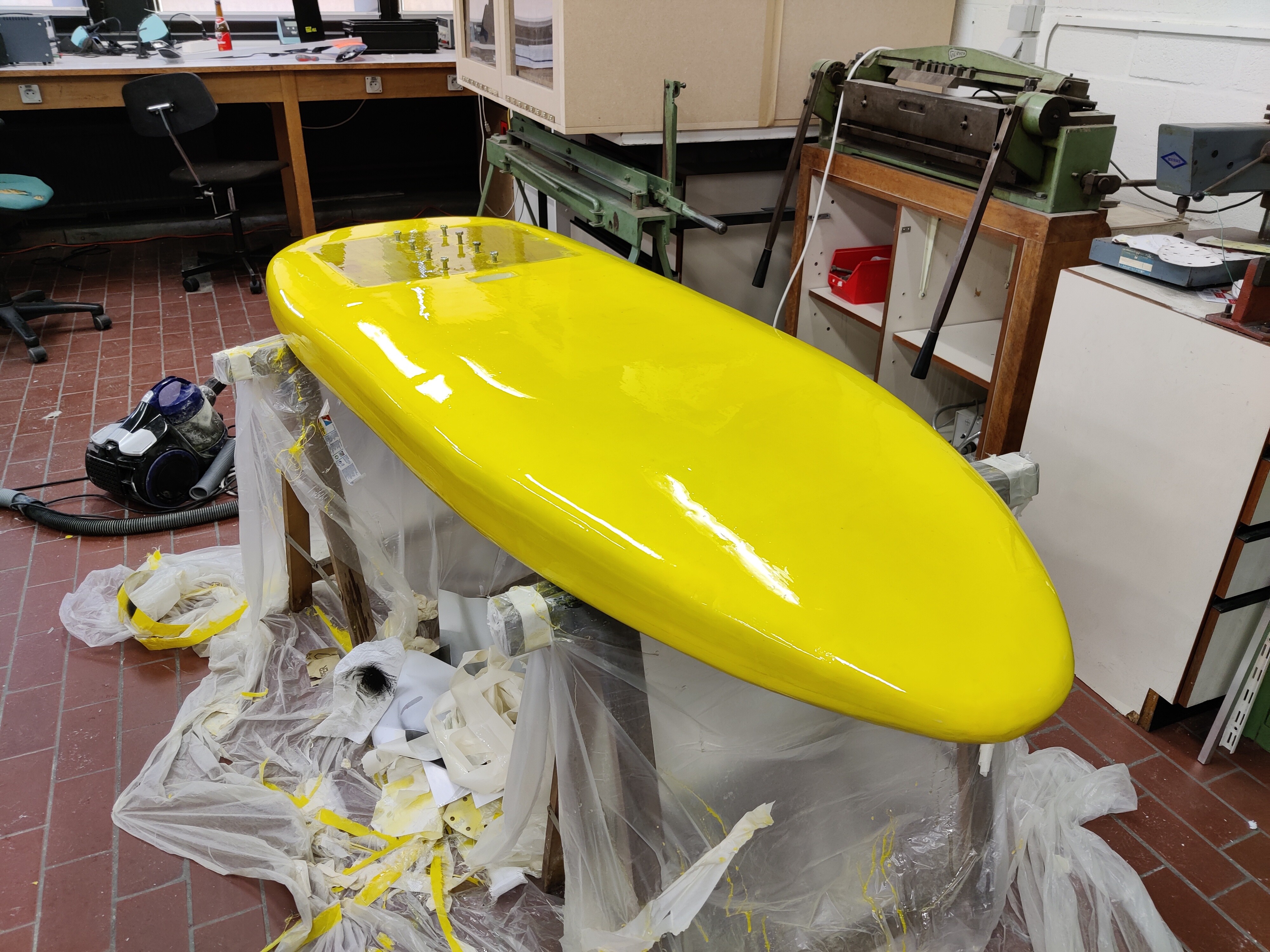
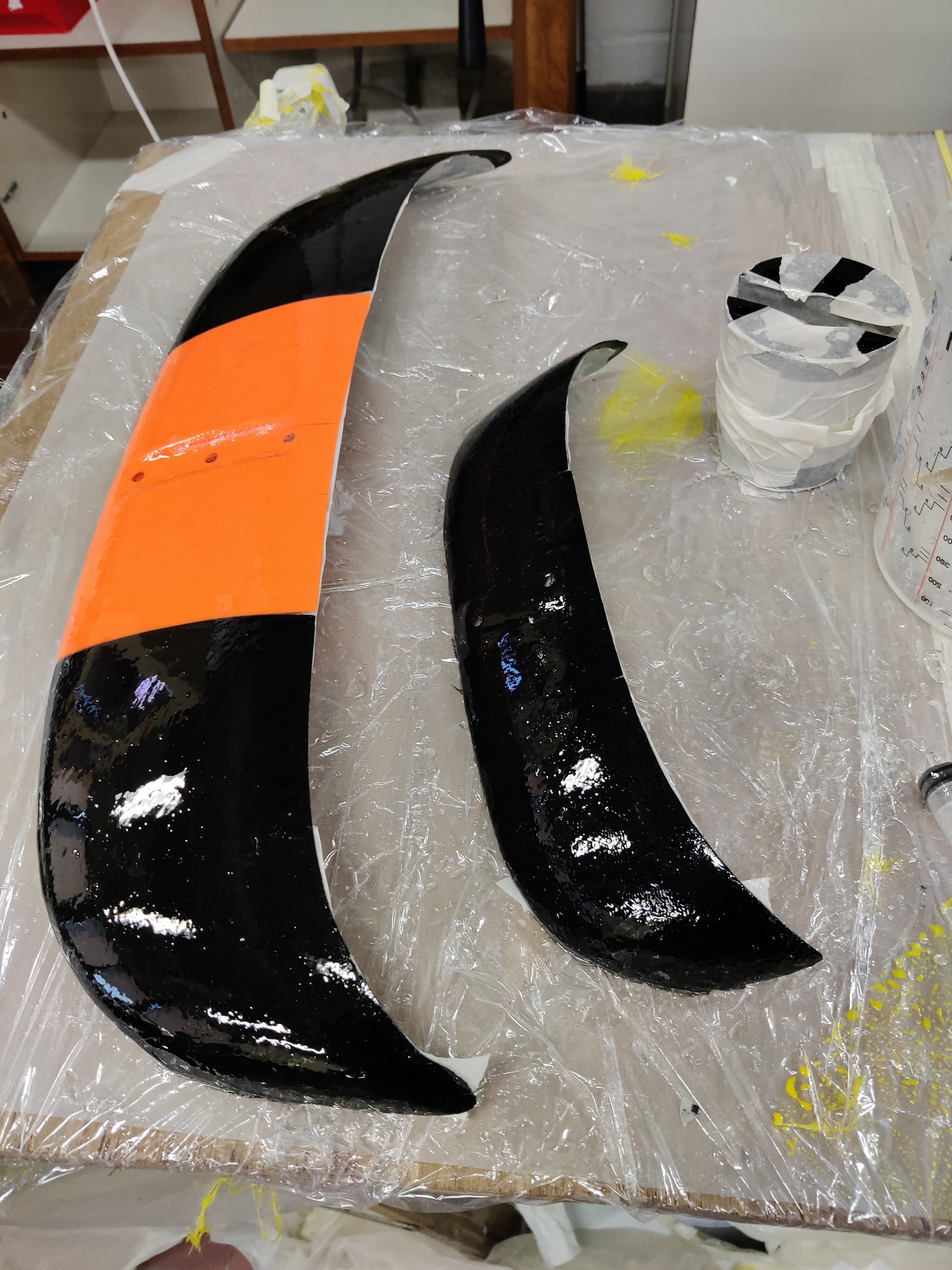
Sanded the whole thing and applied the hot coat on the topside:
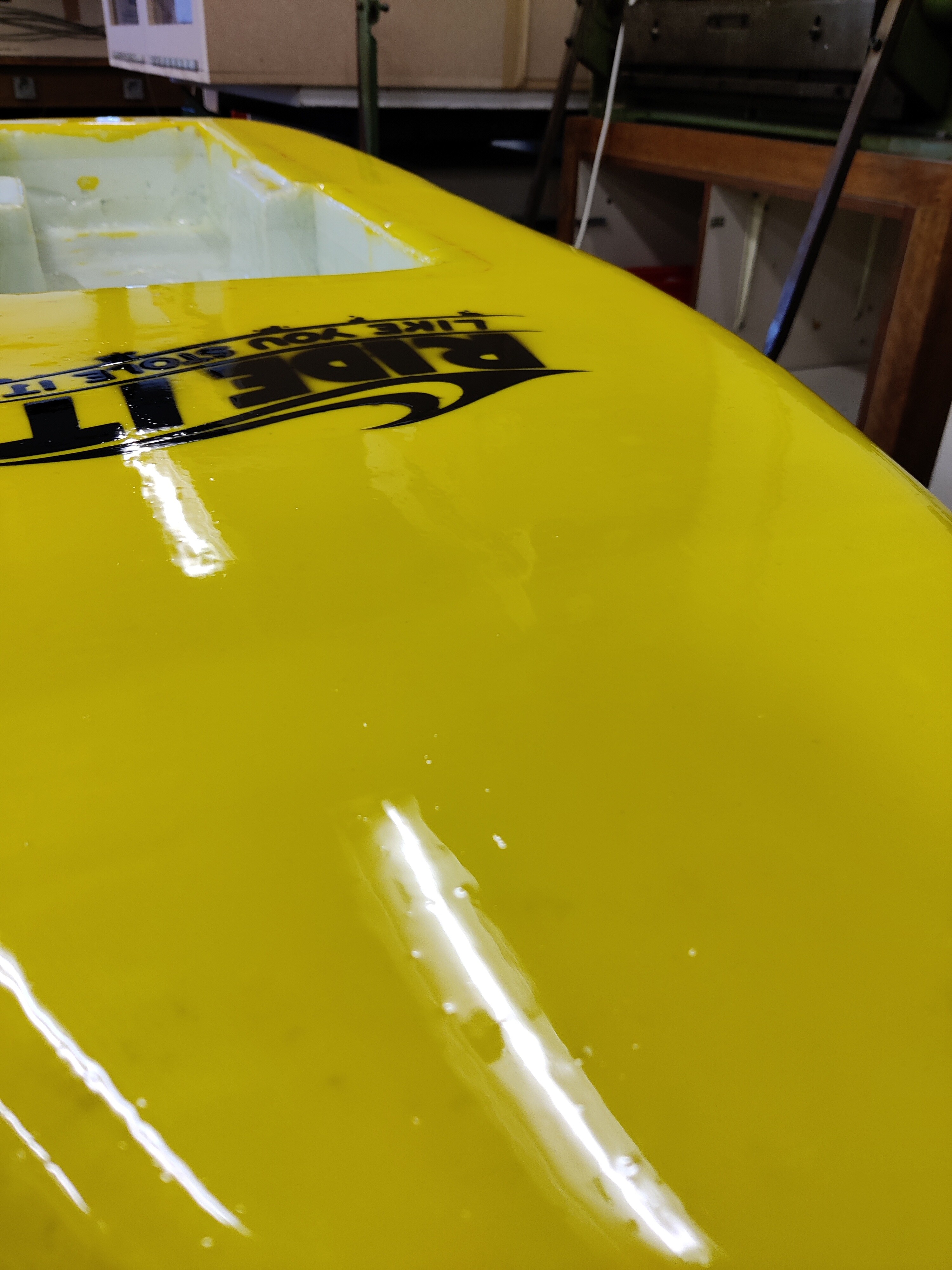
Glosscoat on the topside. Still some bubbles present, but I think Ill forgo sanding and polishing in favor of the natural finish. Also, I don’t have any polishing equipment so ill keep this… Bottom side is for the weekend.
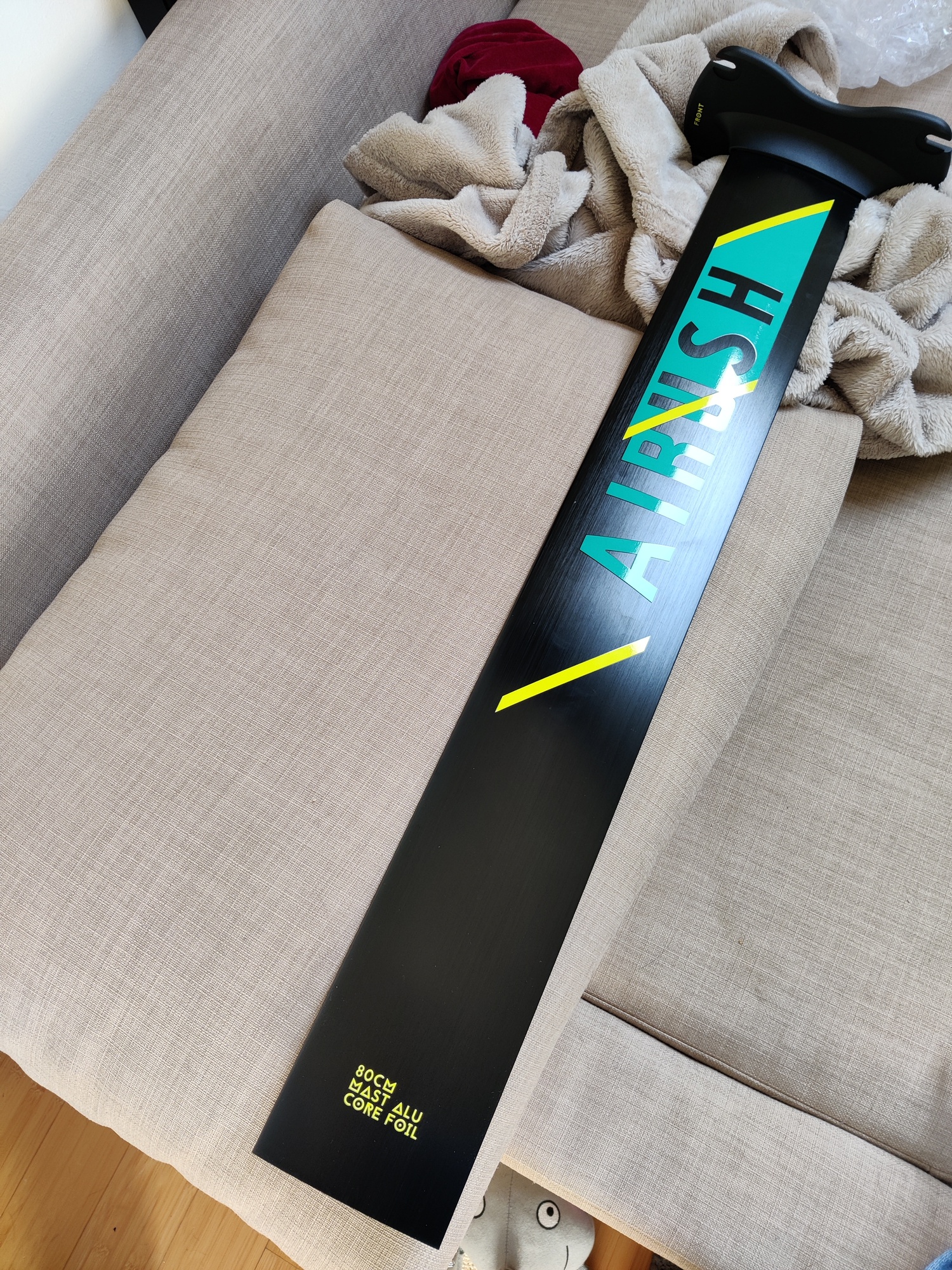
I cracked and bought a mast… Making the 3d printed mast stiff enough seems like a big exercise, and I want to foil rather than spend time in the workshop…
But fret not… I might still make the mast after I’m done with the board. But Ill probably use carbon and vacuum bag it. So I want to take my time for that…
Now time to make the motor mount and glass the wings…
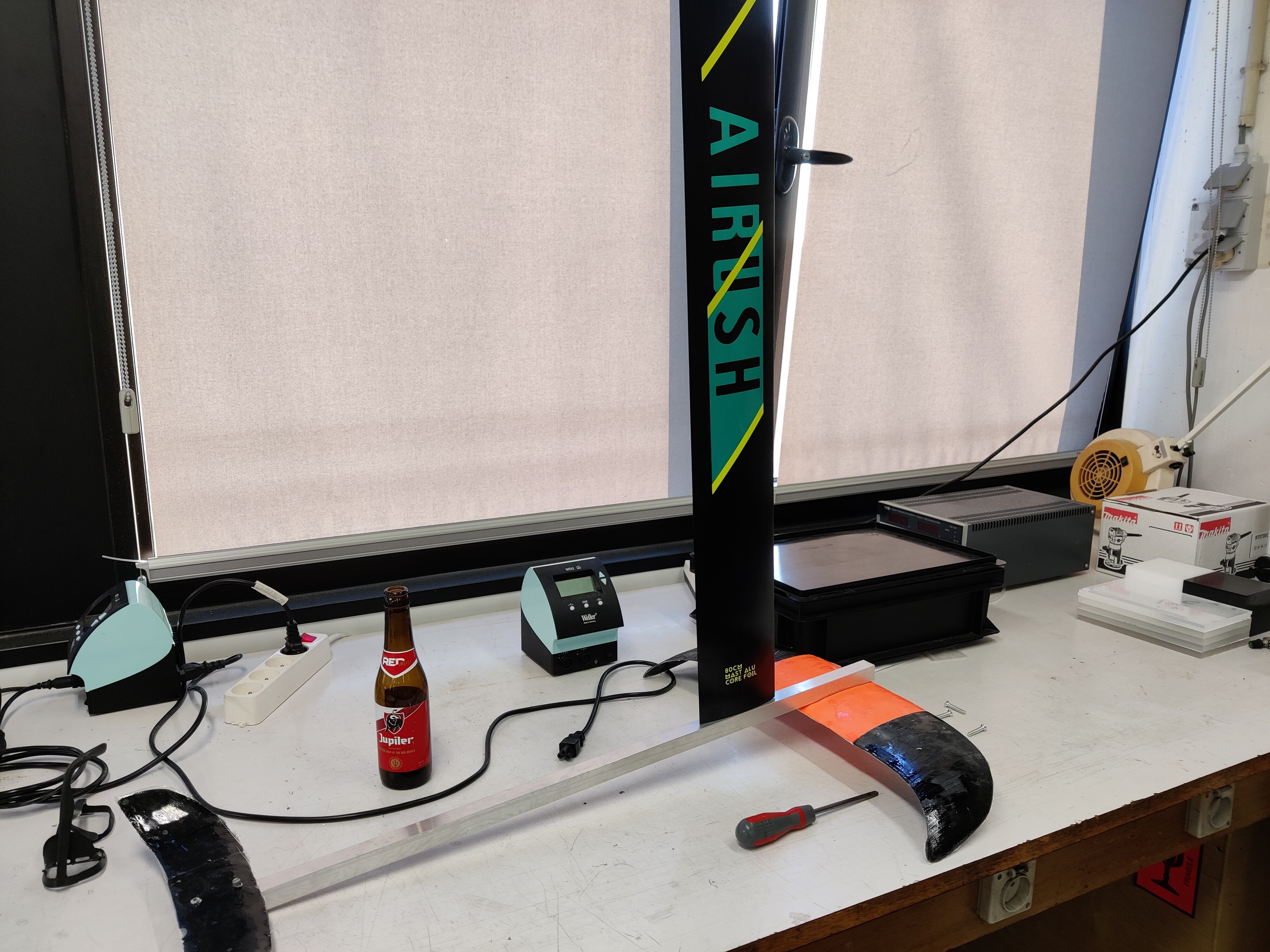
Test assembly of the mast with wings. Aluminium tube of 20mm and a length of 80cm. The wings are mounted onto the tube using rivet nuts. What are the advantages/disadvantages of longer and shorter fuselage? Anyone?
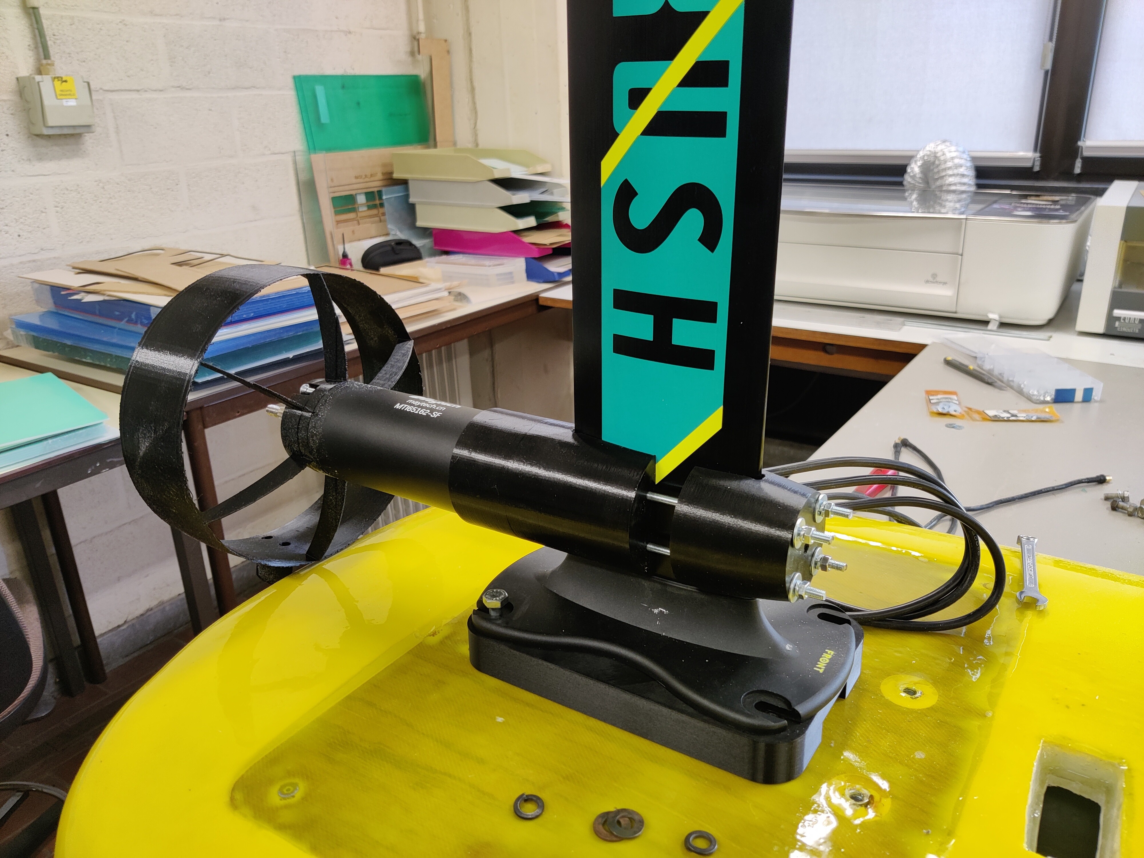
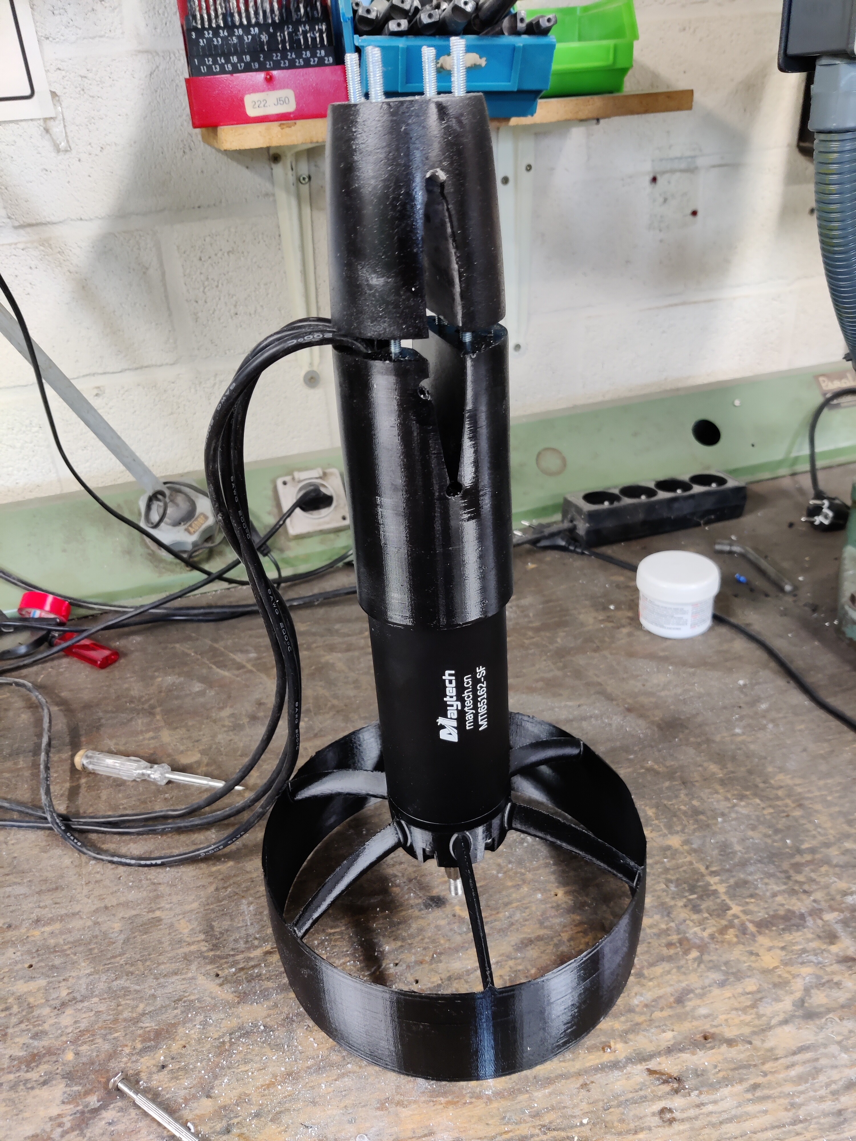
Motor mount testfit. Front part is only partially printed. And at the base of the mast is the adapterplate to adapt the mast-plate bolting pattern to mine.
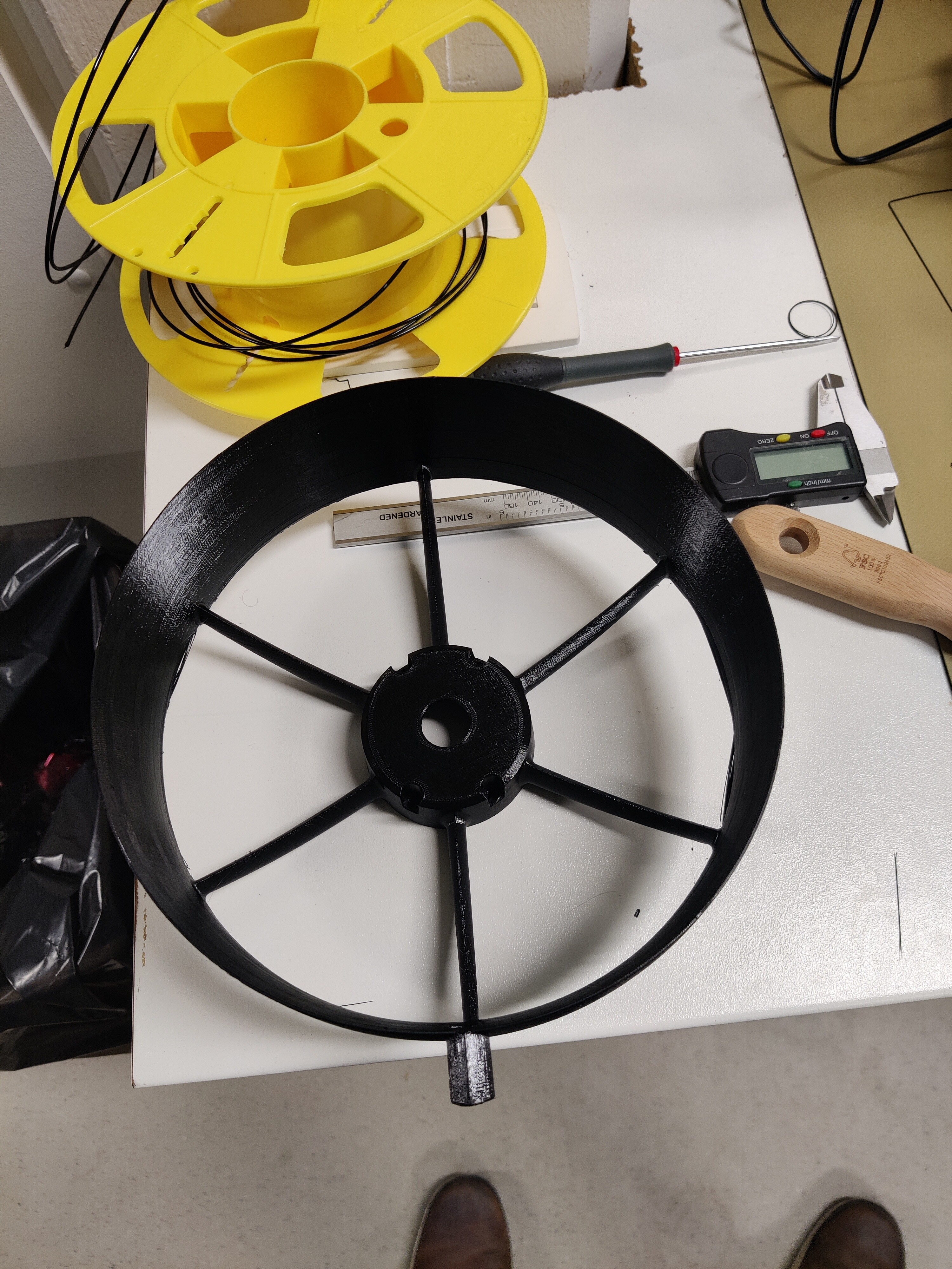
New shroud design. Just whipped up in inventor and printed in PETG. No idea about fluid dynamics though… Not going for efficiency here, just going for foiling.
Glassing some 4mm plywood for the lidplate covering the electronics. After glassing the topside will be covered in textured EVA foam for grip. And the bottom will use heavy duty velcro to keep it in place.
@JvdZ Thanks for the info. ill try it regardless and adjust according to how it handles. Not sure what I can find as alternative in the local diy store…
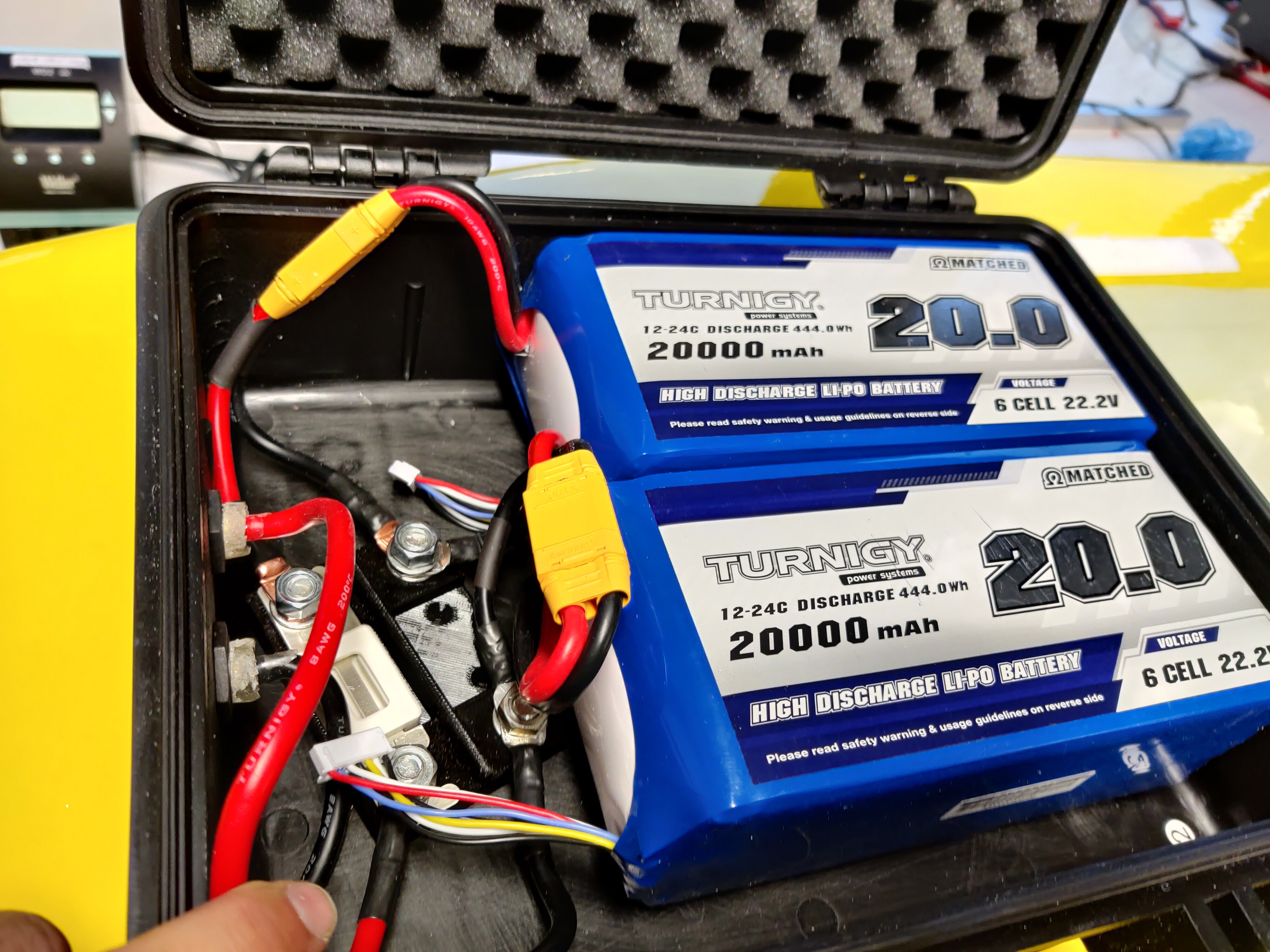
Battery box with fuse and bad cable management. Only recently realized that the cables coming out of the batteries are only 10AWG which seems a bit on the lacking side… I hope they don’t melt…
Anyone know whether the clunking sound before it gets up to speed is normal?
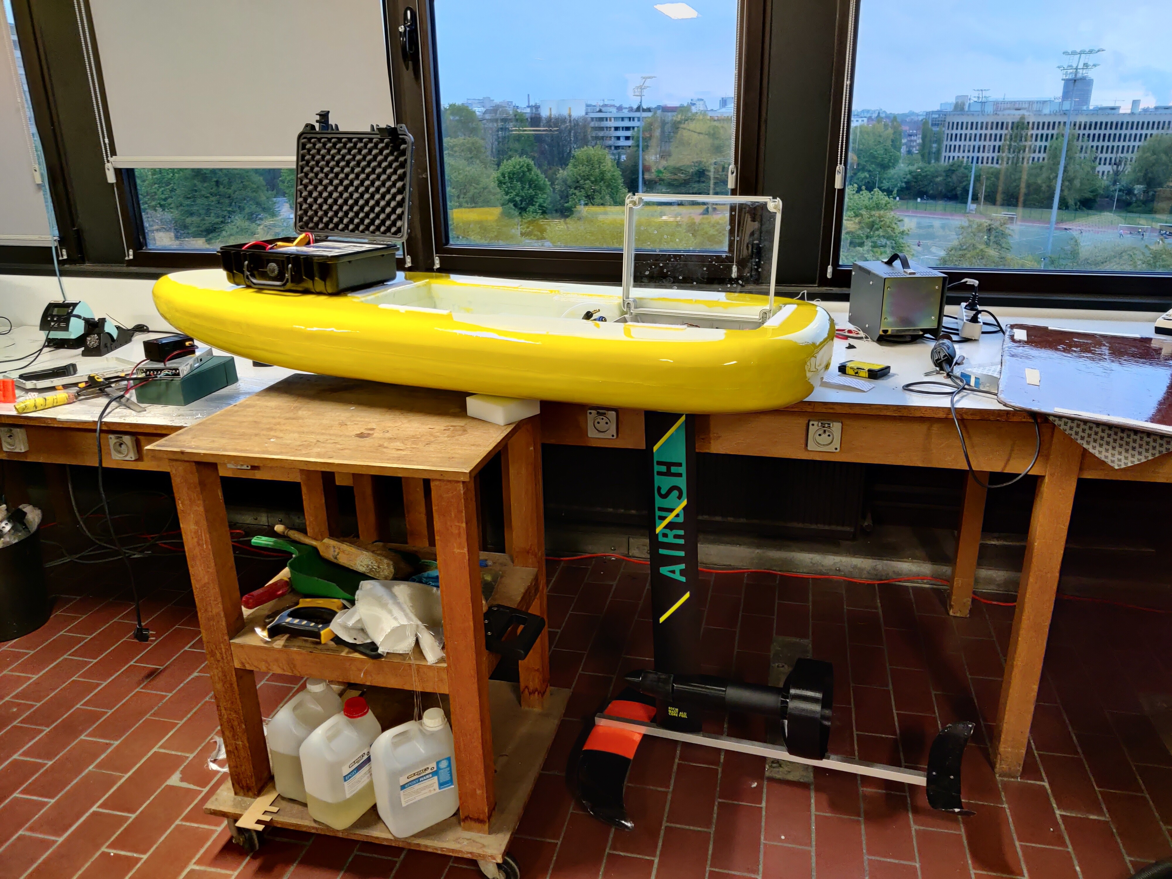
Weight is about 22kg batteries included.
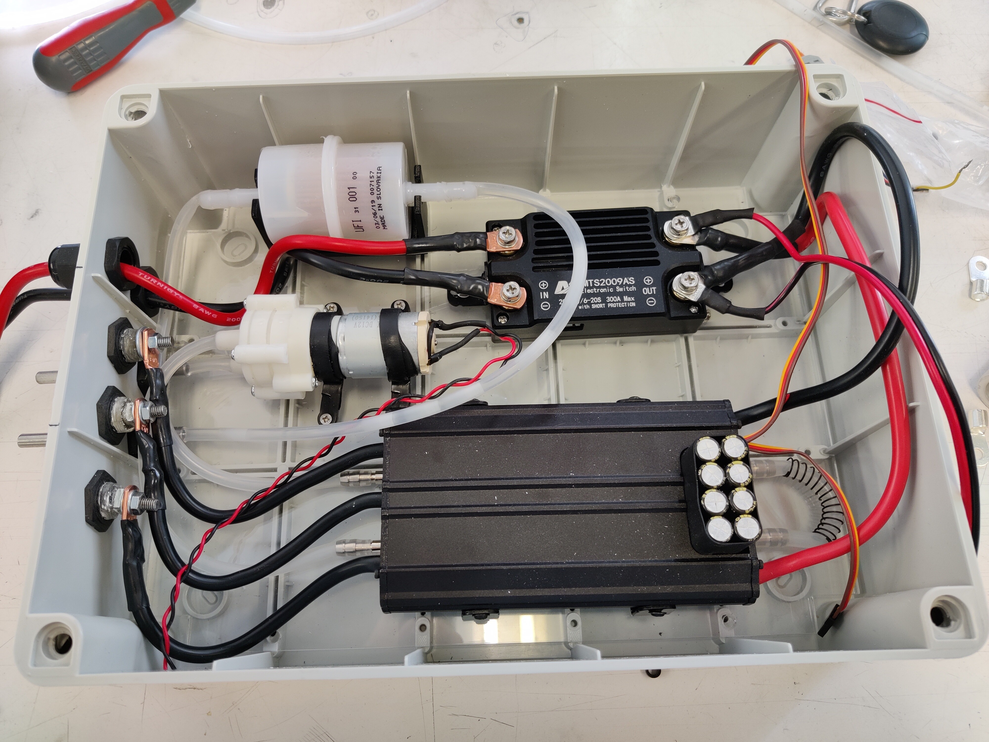
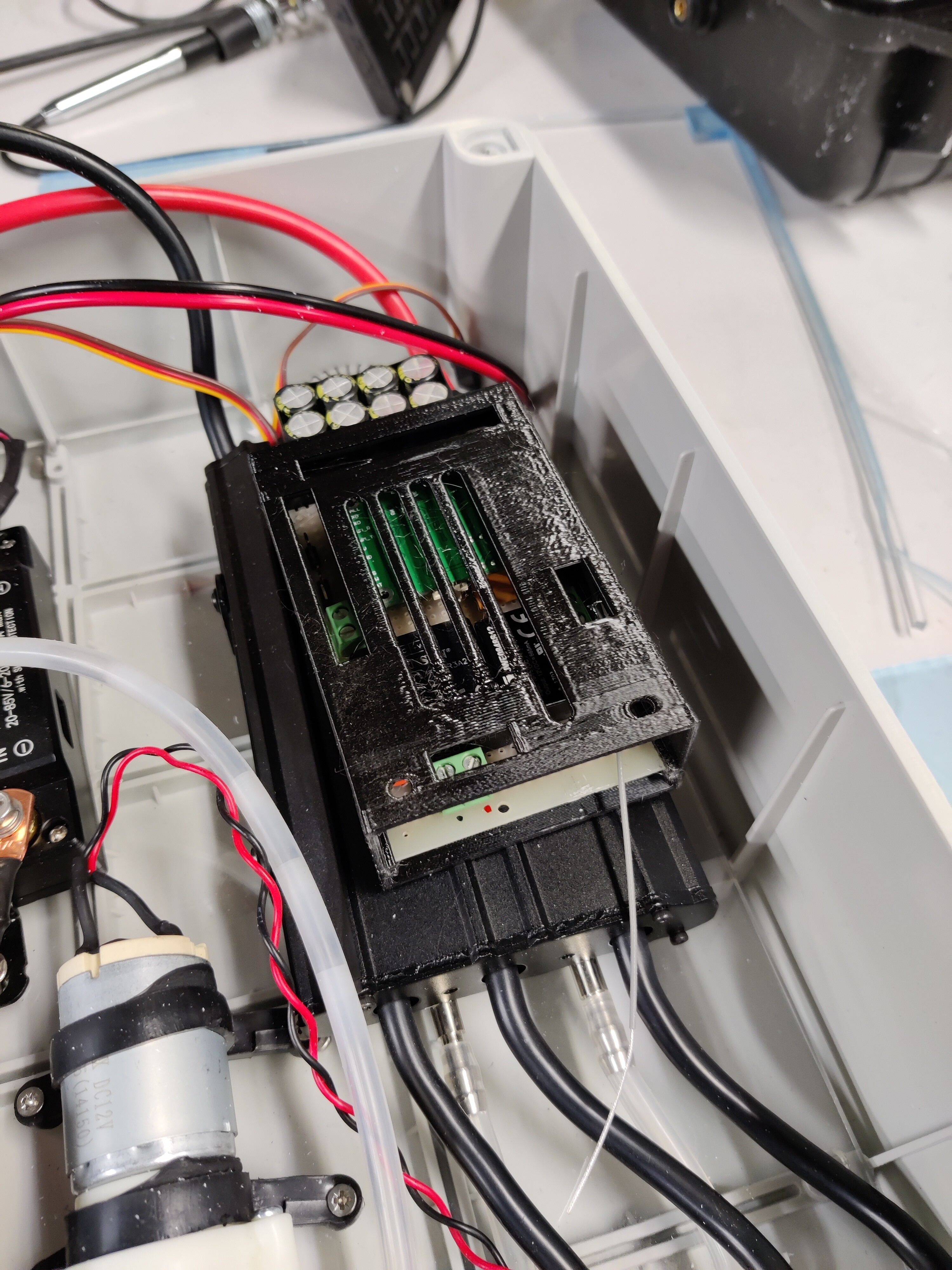
Shorted something and blew the enable input of the no-spark switch when troubleshooting my dead man’s switch. Bypassed it and I almost welded my connectors due to the inrush current of the ESC when connecting the batteries. Need to open it up and check if I can fix it. Fingers crossed…
Still some small stuff to do:
check all wiring and tighten screw terminals
check that the pump works.
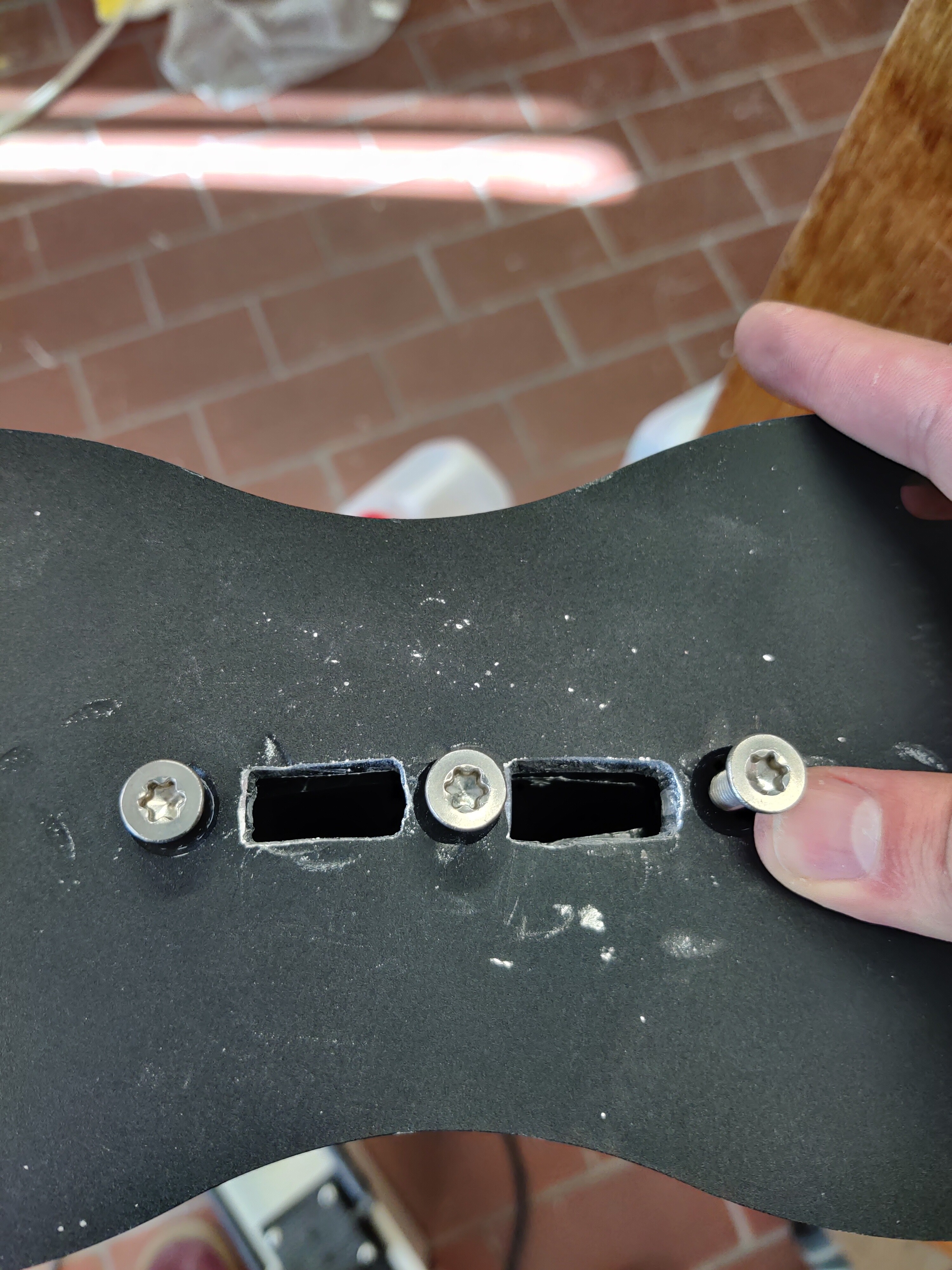
shorten the mast screws so I can tighten them without crushing fiberglass
Attach propeller and maybe modify it (for later) of print a better one
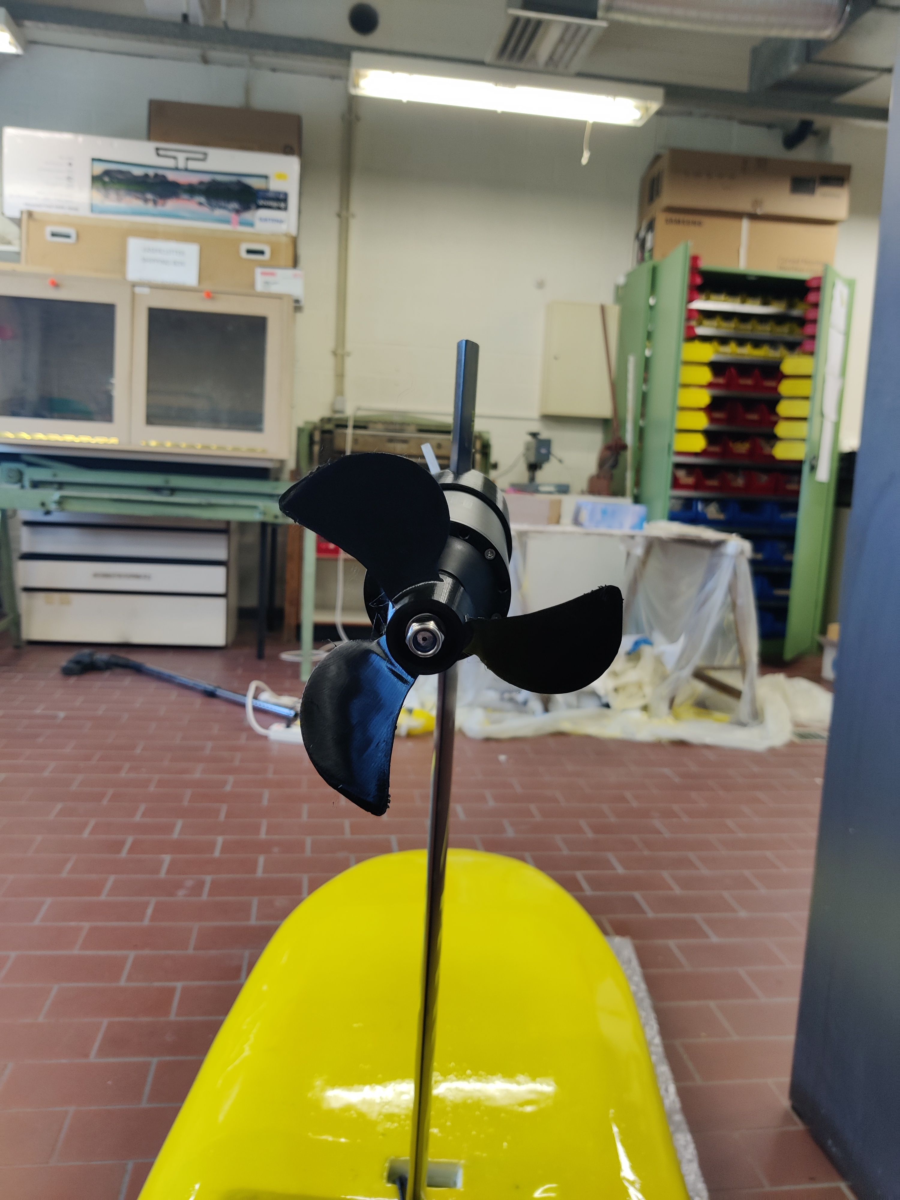
First test this weekend was a big fail… lost the prop within minutes due to not using a nylon nut, and bad mounting due to interference with the shroud. But at least the board floats! There is some slight water ingress in the control box so I will need to figure out where the leak is.
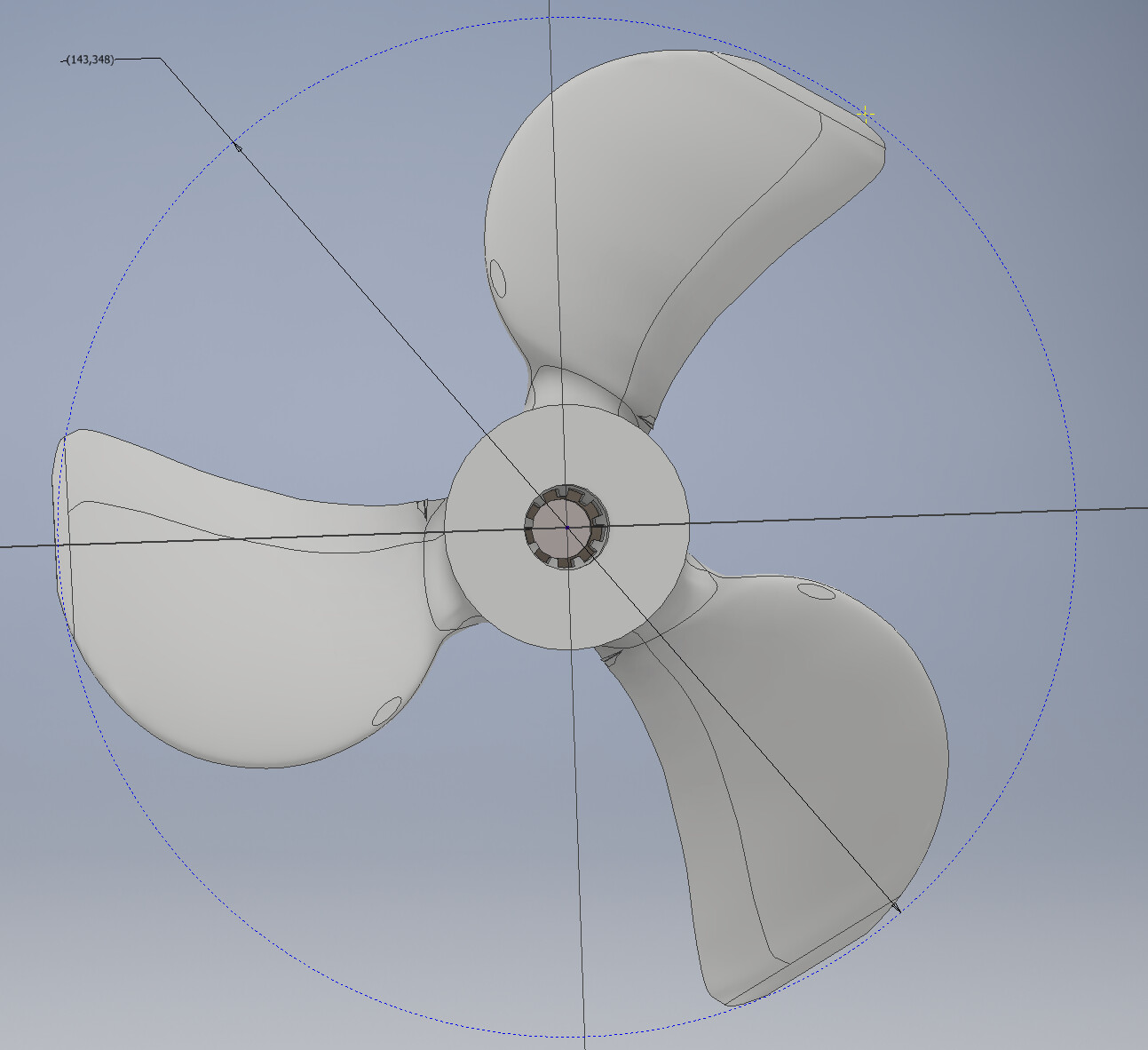
I printed a new propeller for my maytech 65162 based on the STEP file from @JvdZ.
Loaded the step file in inventor, modified it to fit the axle with teeth instead of the Flipsky pin mounting.
I also made some scaled variations on the prop for trials to see which gives the best ride. I might try the parametric prop generator later on, but I want to get out on the water and see if it foils sooner rather than later.
How do you guys reinforce the prop? Is it necessary?