Hi together,
Everybody here needs battery packs for foiling.
Many build these packs their own, wondering how thick the nickel strips need to be, how hot they will get, and if they even need nickel or if maybe steel is enough.
From my perspective, many people go way overboard on the thickness and most people could just use steel, from electric point of view at least (for rust, pure nickel may be better).
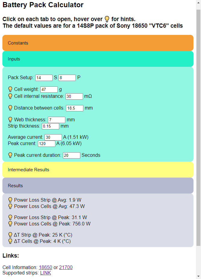
Give the calculator inputs about your pack, like S&P Cells, Cell resistance, Strip width, … and get information about dissipated power and thermal increase of strips and cells.
From that, you can make an educated guess, which thickness is enough.
That’s a great initiative! Many chase one percent improvement on the connection level while still driving the batteries hot and this type of calculator will show the relative level of thermal losses created.
It would be good to make this difference clear by showing the cell/strip heating relation as a number (in your pic it would be 24x higher thermal losses from batteries than from strips)
One thing: I doubt the strip heating temperature is correct since it is thermally connected to the batteries - if the calculator just uses the thermal mass of the strip and power loss to calculate that?
Thanks for the feedback
I will include percentage of Cell to Strip loss.
Yes, the calculator pretends, all energy lost in the strip is only going into the strip, in reality, most will be dissipated or go into the cells. So the calculator will tell you worst case, in a vacuum,…
But still you can see even with 0.15mm Nickel at 120A it only gets 25K hotter, so no need for 0.3mm Nickel or stuff like that.
Not really sure how to thermally model the thermal resistance from Nickel to cell, as this will probably depend on weld type, amount of spotwelds, …
If I had a average thermal resistance per Cell, from Nickel to cell, I could implement this as well.
Percentage of power lost in Strip and Cells (as requested by @Larsb)
Another thermal simulation for the strips, according to “ANSI / IPC-2221/IPC-2221A design standards for PCB trace width”
Not sure how accurate this is, probably also depends on amount of thermally conductive/isolaive materials around the pack. But now there are two indications about thermals of the strips.
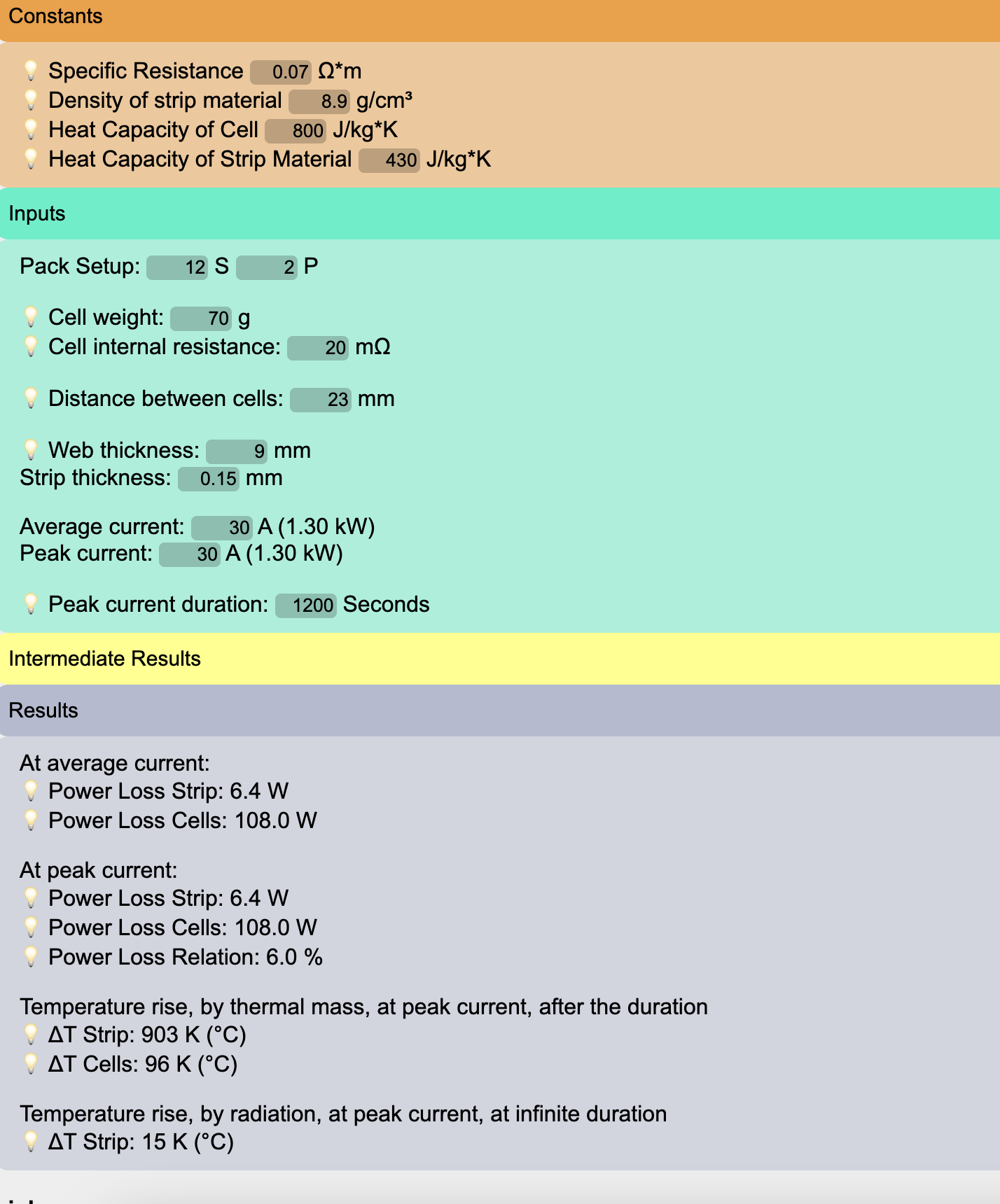
I wanted to see what happens to the strip and to molicel p42 12s2p battery pack temperature after 20m. So I set peak current to the probable continuous current - 30A.
And got these strange results - regarding the temperature rise.
(I must adapt the system such that battery is bellow 60c).
The calculator of course does not account for thermal loss to the environment. But anyway, 110W is not small at all, considerating the outside temperatue can be 35c and direct sunlight, there is only 30c of permisible temperature rise.
Of course this is supposed to be foil-assist build, so 20m is only an emergency. But at least after 20m the batteries must not be damaged.
BTW I dont think you will be able to pull 15A/cell for 1200 seconds… Lets say the cell has 4Ah of useable capacity, 4Ah/15A = 0,266h = 960sec. before the cell is depleated. At the high current you will rather only get 3.8Ah out of it, so only 15min. / 900sec.
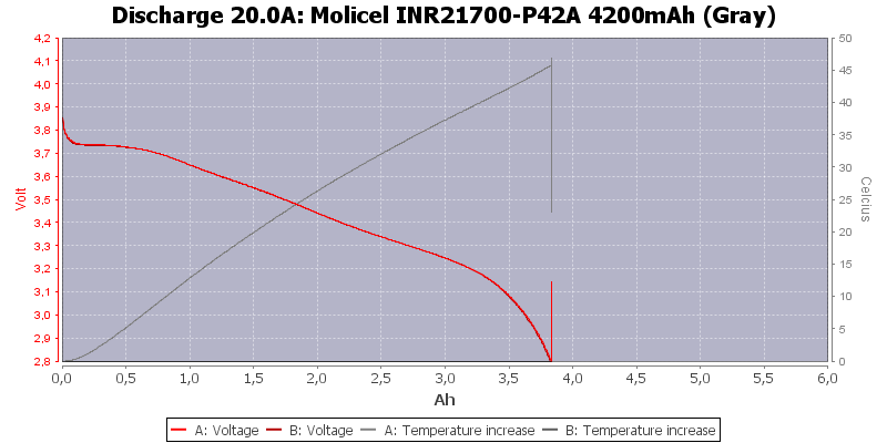
Yes, thats one of the problems with using the cells at high current - you are pushing 15A per cell. As you can see here, at 20A, a P42 heats up quite substantially. Probably the 20mOhm from lygte is a bit off, so in reality you wont get 96K but rather the 45K as shown by the graph.
But just from calculation:
15A * 15A * 0,02 Ohm = 4.5W/cell
With 800J/kg*K and 70g weight, thats 56J a cell can take for getting 1K warmer
And 4.5W * 1200s = 5400Ws = 5400J
So 5400J / 56J/K = 96K
So the calculator is right on a purely ideal physical level…
Sure the battery is gonna dissipate some of that heat and probably the internal resistance is better than 0,02 Ohm. But to find out by how much, I guess you will have to do a test. Also, consider aging (which is exponentially accelerated by high currents) of the cells increases their internal resistance…
Yes, I have seen this graph…The temperature rise for the battery is indeed logical while not considering thermal losses. But the strip temperature rise by 500K while heated by 5W . In reality strips are connected to the batteries, so they stay at the same temperature as the batteries. Probably they contribute to the overall temperature rise by 5W/110W.
You added here good points to consider , thank you.
I am considering 12s2p or 10s3p or 12s3p. To be on the safe side is either 10s3p or 12s3p and then at 30A it is more than 20m efoil . To maximize the 6384 motor potential probably better 12s3p, I just don’t know if 120kv is a good match…
For such long durations, please use the strip temperature calculation at the bottom (showing 15K)
Yes, but with 3S instead of 2S, also the current per cell falls from 15A to 10A, and as the current is squared in the power loss calculation, also the power loss is gonna fall from 4.5W/cell to 2W/cell, resulting in less then half the heat! So 3S will only be 42K over 96K
@ludwig_bre Could you please post your equations, or a link to them, to see the math this calculator is doing in the background? I’m trying to understand the math behind this calculator.
As far as I remember I first calculate heat energy created by the electric current as well as heat capacity in the parts. And then there is a complicated formula copied from the IEC standard for PCB trace heating.
function calcAll()
{
	var spec_res = parseFloat(document.getElementById('spec_res').value);
	var dens = parseFloat(document.getElementById('dens').value);
	var heatcap_cell = parseFloat(document.getElementById('heatcap_cell').value);
	var heatcap_strip = parseFloat(document.getElementById('heatcap_strip').value);

	var n_series = parseFloat(document.getElementById('n_series').value);
	var n_para = parseFloat(document.getElementById('n_para').value);
	var weight = parseFloat(document.getElementById('weight').value);
	var cell_res = parseFloat(document.getElementById('cell_res').value);
	var length = parseFloat(document.getElementById('length').value);
	var width = parseFloat(document.getElementById('width').value);
	var thick = parseFloat(document.getElementById('thick').value);
	var avg_cur = parseFloat(document.getElementById('avg_cur').value);
	var peak_cur = parseFloat(document.getElementById('peak_cur').value);
	var cur_dur = parseFloat(document.getElementById('cur_dur').value);

	var sq_area_btw_groups = width * thick * n_para;
	var res_btw_groups = (spec_res * (length/1000) / sq_area_btw_groups) * 1000;

	var all_cell_weight = n_series * n_para * weight;

	//1.st: calculate total area of one strip (can be approximated as 3*width*length)
	//2nd: multiply with thickness to get volume
	//3rd: from volume, get weight
	//4th: Multiply by amount of S-cells
	//                          111111111111111111111111111   2222222    3333333333333   44444444
	var all_strip_weight = ( ( (3 * width * length * n_para) * thick ) * (dens/1000) ) * n_series;

	var total_res_strip = res_btw_groups * n_series;
	var total_res_cells = cell_res / n_para * n_series;

	var p_avg_strip = total_res_strip/1000 * avg_cur * avg_cur;
	var p_avg_cells = total_res_cells/1000 * avg_cur * avg_cur;

	var p_peak_strip = total_res_strip/1000 * peak_cur * peak_cur;
	var p_peak_cells = total_res_cells/1000 * peak_cur * peak_cur;

	var temp_rise_strip = (p_peak_strip * cur_dur) / (heatcap_strip * all_strip_weight / 1000);
	var temp_rise_cell =  (p_peak_cells * cur_dur) / (heatcap_cell * all_cell_weight / 1000);

	//Calculation from ANSI / IPC-2221/IPC-2221A design standards for PCB trace width
	var iec_a_int = 0.024;
	var iec_a_out = 0.048;
	var iec_b = 0.44;
	var iec_c = 0.725;

	var area_mil = (sq_area_btw_groups / n_para) * 1550 * (0.018/spec_res);

	var temp_rise_strip_iec_int = Math.pow((((peak_cur/n_para) * (Math.pow(area_mil,(-iec_c))))/iec_a_int),(1/iec_b));
	var temp_rise_strip_iec_out = Math.pow((((peak_cur/n_para) * (Math.pow(area_mil,(-iec_c))))/iec_a_out),(1/iec_b));

	document.getElementById("sq_area_btw_groups").innerHTML = sq_area_btw_groups.toFixed(2);
	document.getElementById("res_btw_groups").innerHTML = res_btw_groups.toFixed(2);
	document.getElementById("all_strip_weight").innerHTML = all_strip_weight.toFixed(0);
	document.getElementById("all_cell_weight").innerHTML = all_cell_weight.toFixed(0);
	document.getElementById("total_res_strip").innerHTML = total_res_strip.toFixed(2);
	document.getElementById("total_res_cells").innerHTML = total_res_cells.toFixed(2);

	document.getElementById("p_avg_strip").innerHTML = p_avg_strip.toFixed(1);
	document.getElementById("p_avg_cells").innerHTML = p_avg_cells.toFixed(1);
	document.getElementById("p_peak_strip").innerHTML = p_peak_strip.toFixed(1);
	document.getElementById("p_peak_cells").innerHTML = p_peak_cells.toFixed(1);
	document.getElementById("p_rel").innerHTML = ((p_peak_strip/p_peak_cells)*100).toFixed(1);
	document.getElementById("temp_rise_strip").innerHTML = temp_rise_strip.toFixed(0);
	document.getElementById("temp_rise_cell").innerHTML = temp_rise_cell.toFixed(0);

	//document.getElementById("temp_rise_strip_iec_int").innerHTML = temp_rise_strip_iec_int.toFixed(0);
	document.getElementById("temp_rise_strip_iec_out").innerHTML = temp_rise_strip_iec_out.toFixed(0);

	document.getElementById("avg_power").innerHTML = ((3.6*n_series*avg_cur)/1000).toFixed(2);
	document.getElementById("peak_power").innerHTML = ((3.6*n_series*peak_cur)/1000).toFixed(2);
}
I’ve finally had a chance to look into this. This is a neat way to calculate ampacity. I hadn’t had thought of this. I’ve been trying to find a reliable way to calculate ampacity of nickel strips for a very long time now. Every table I look at has different values. So there appears to be no standard. Making me want to just go with copper, because it’s current carrying capability is much more well documented. I just don’t want to spend hundreds of dollars on a spot welder.
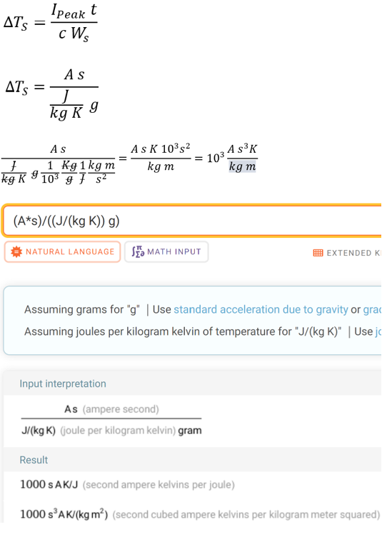
I’m trying to follow along with the math here, and had one question.
The change in temperature for the strip appears to be calculated via the formula below.
Doing a unit of measurement check on this, i just plug in unit of measurements only.
I then do some conversions and I do not get Kelvin alone in the numerator.
I put this into Wolfram Alpha just to double check that I hadn’t made a mistake.
Calculating with the heat capacity is in my opinion not the best way, as it does not account for any radiative cooling that occurs. That’s where the IPC is way more reliable, so I would focus on using and understanding this formula for a table / …
Anyways regarding the units
On the beginning of your formula you use Ipeak, but it should be Ppeak (peak power) which unit is Watt (W) also can be converted to J/s (Joule per second)
With that J/s and s simplify to J on the top part of the division
And the bottom consisting of J/(kg*K) and kg simplify to J/K
And with that the whole division is
J/(J/K) which can be further simplified to K
Thank you! I think you are correct about the units of measurement. I appreciate it. Have you had any luck on calculating or estimating the heat transfer coefficient for nickel to air?
Depends on your setup and where you are.
If the surrounding temperature is 30°C, and the strip has an additional heating of 50K it will end up at 80°C. That’s usually also the maximum comfortable operating temperature for battery cells, semiconductors,…
Kelvin (K) is just the fancy (and scientifically correct) way to express delta temperatures in the “celsius system”


 . In reality strips are connected to the batteries, so they stay at the same temperature as the batteries. Probably they contribute to the overall temperature rise by 5W/110W.
 . To maximize the 6384 motor potential probably better 12s3p, I just don’t know if 120kv is a good match…