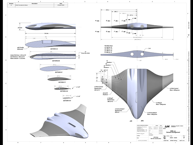
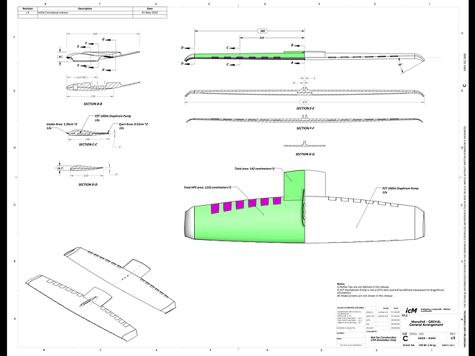
So, as I now have some time to revisit the “outside of the design box”, I attach a General Arrangement dwg for a family of 4 BWB Foils with a non-traditional thrust concept. The Thrust Concept will be illustrated in the Propulsion Group forum.
A “notional” e817 foil is used to define all chord stations, thrust defined the ct, and therefore the cl. The planform for the c1 configuration is an aero model, and will be modified as CFD pressure contours are refined, Planforms d1, e1 and f1 are “sportier” configurations … at least that is what I am hoping for … 
My hope is that I can get feedback from current riders (I am not) as to potential maneuverability performance, especially with respect to active control surface sizing to minimize design revision iterations. I will be posting cp contour maps total drag and lift. Please note that CFD should not be considered a validation as 20% variance from tests is not unusual.
So please feel free to rant or rave (with supporting guidance)
robert/
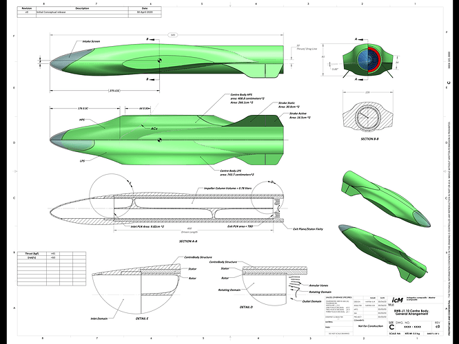
Ok, so in consideration of the variety of riding styles/use … The c1 BWB concept has been downsized and modularized to allow for various spans, Foils, fwd/aft sweep, taper, twist, and detachable Winglet plates, “C” and “J” tips. The J1.10 special propulsion will be a single Direct Drive, Axial Flux Ring Motor with a single Helical “Impeller”. The illustrated impeller pitch is optimized for low revs. Not sure if I can “stuff” the Stator and Rotor active area into the allocated Height and obtain required N-m … will know better after the EM Field simulations.
As before, comments pro and con are welcome as guidance at this stage will hopefully mitigate “rabbit holes” 
1 Like
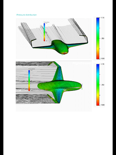
This image was “borrowed” from a University of Aachen Design Study from a few years ago. I should be so lucky with the cp contours after having inverted the wings and simulated the J1.10 in water …
What would be of initial help for simulation would be a typical “mission profile” which defines nominal maneuvers. Supplementary profiles could define expert level riding, but not extreme …  the extremities need to be separated from the 95% of the users …
  Aircraft design parlance knows them as “Scatter Factors”
Your project is a flying wing. To be pleasant to ride, it needs either actuated flaps or a reflex airfoil section.
Foils with GBS using flaps should be on the market this year:.
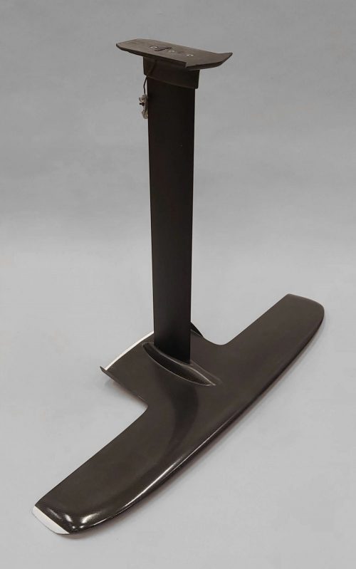
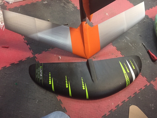
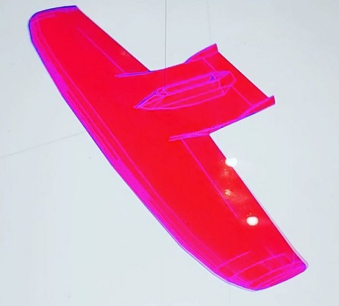
In the meantime, you need to change your E817 profile by a reflexed airfoil section. Still in development, originally designed for surf/sup surfing, this is the Singlewing project designed by a guy called Gurval LEGO. A hybrid tailless hydrofoil. 1380cm2, wetted surface reduced to a minimum with a small reflexed “tail” for stability. Good stability, manoeuvrable and … fast.
1 Like
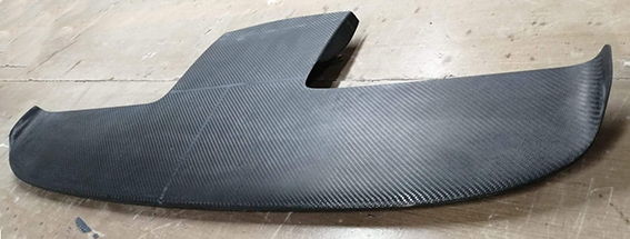
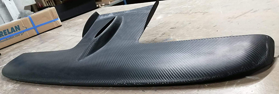
Hmmm … so by going to the e34x series I get reflex and thickness thereby cleaning up my HPS? … the J1.10 included canted Strakes at the Thrust Exit with 30-40% Primary Control Surfaces (DIY Piezoelectric Actuation) … are the Flaps indicated on the Gurval LEGO. Main Wing TE considered primary control or trim? Is 1380cm2 considered a “sporty” value! Has anyone considered/tried J or C Winglets to reduce span, move AC Aft while maintaining area? The span looks like about 750 with good robustness … am I correct? Thx … robert
Very nice lofting on the tips and reflex! … the bar has been set! 
3 Likes
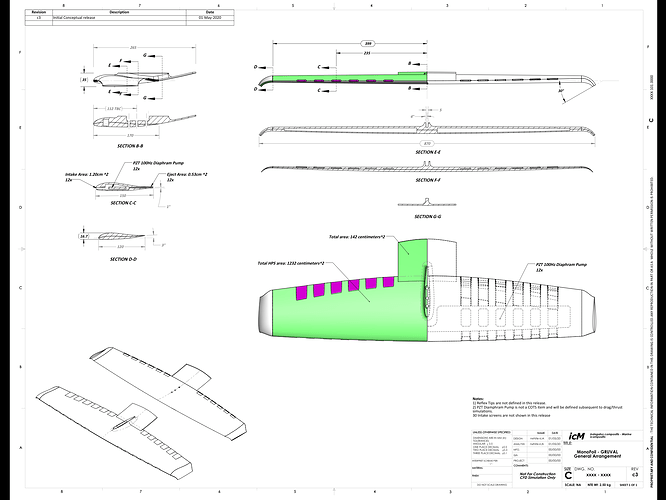
Ok SoEFOIL your suggestion has me going down a different fork (hopefully not a rabbit hole  I have been looking at Piezoelectric Micro Pumps for a while now. Gruval’s Foils with propulsion is a serious packaging problem … so below I attach a Flauvel 14% “Flying Wing” as a potential solution. An interesting opportunity to provide asymmetric thrust for supplemental maneuvering and trim will exist if the right controller were developed. Downside of the PZT pumps are their limited life (5-10k hrs)
Lets try this again … amazing what 18kb can mean on pdf drawing …
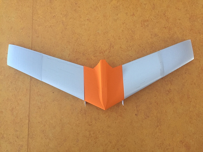
Nice concept. I am working on something similar. A “only wing” configuration. It Uses a special wing profile, so I hope no need for stabilizer.
3 Likes
For people interested, the “secret” of flying wings is the reflex profile creating more drag than a non reflexed one but necessary to maintain the wing horizontal without stab AND/OR the light twist (2-5 degrees) either proportional and continuous from wing roots to wing tip or blended starting, say, at 50% wing length to wing tip.
One mast and one wing: interesting project for your manufacturing technique @visor360 
1 Like
 Very nice! … I look forward to the water trial results!

