I have everything ordered and delivered, except the PCBs. I will order the PCBs this week also. But that’s not cheap. Min. 5 pcs, totals well over 100 eur with shipping to the EU. This cost is the only drawback of the project so far.
Hi Everybody,
Thanks for the feedback.
In Germany, 4 People (other than me) have built one: @kotnascher@superlefax@sat_be and Arne (dont know his Forum Name)
Maybe they can also share their thoughts, but the feedback I got was “It was so fun to build, I want to build another one”
For a german efoil group I have managed the ordering of the PCBs. There we have managed to get 30 orders.
At 30 PCBs (each Rx and Tx), I am at 19€ incl. shipping and taxes to germany for both.
I also envision, that people from the same country get together and order in groups.
Also, in EU, you can also contact me, then I can send you PCB already including the Bootloader for 30 Euro within Germany and 35 Euro within EU (incl. shipping).
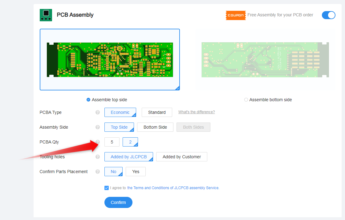
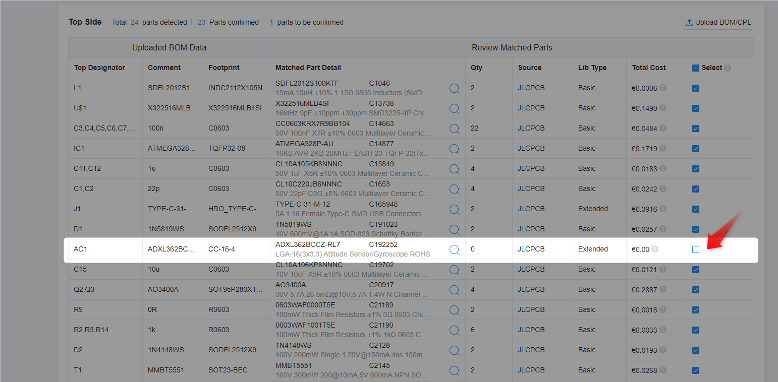
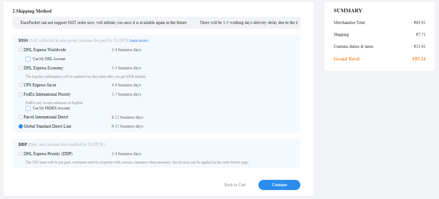
Btw, MOQ for PCB is 5, but MOQ for the assembly is only 2, so if I look the prices up, 2 each of Rx and Tx is about 85 Euros to EU (so if you share with another person, 42 Euro per person)
I built one as part of the beta testers. Although I haven‘t tested it on the water yet, I can say it is well desingned. Ludwig thought about every detail and he already provided several updates (hw and sw). I was also able to adapt the ppm timing in the code to my preference.
I think if you can do a group order or get a kit from Ludwig, this is a very god remote for the money. You can always update it if there should be bugs or new features oposed to many chinese remotes. The only drawback is you need some skills and tools to build it yourself and also need to flash the code (which is not too difficult).
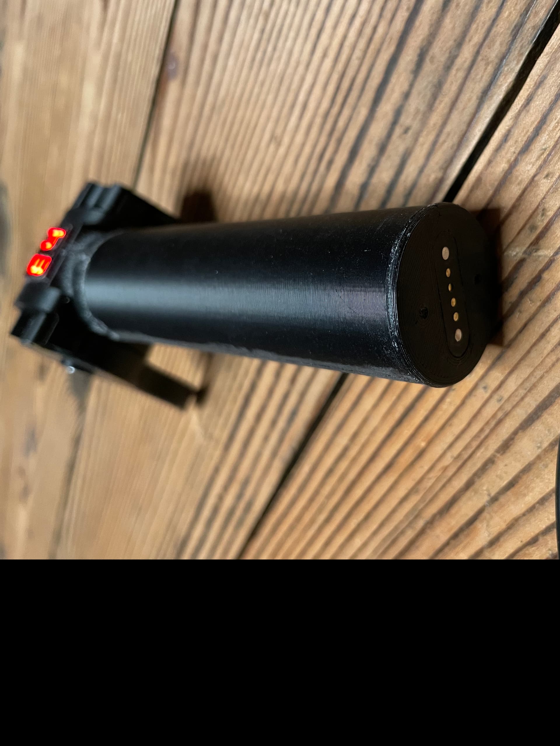
The „waterproofing“ with expansive foam is an innovative solution, no long term test result yet, time will tell.
No, haven’t tried them, as I have had good experience with JLC for many years now.
But if someone does order the BREmote at another manufacturer, feel free to share the reults here
I just sent all the files to my unknowing 3dprinter pal for printing and realised it would be super useful with a stepfile with the completed assembly - both to be able to spin it round in the cad and see how it’s assembled and for modification if one wants to do some changes.
Working with STLs in Catia (as i do) is a nightmare so having the STEPS is a dream for me - pleease!
Thanks, i checked the other links already before i asked here and had sent them on.
Only thing was the readme.md that i couldn’t open since my computer didn’t know the extension - but my friend knew that it was basically a txt file that opened with notepad.
Made a new build instructions video.
The old one was still a bit rough and missing a common thread. Also, the SW installation part is now shown in all details.
Important information:
Found a bug that could deplete battery in standby
Please update to / use Release 1.4.2 or later! GitHub
Additional Update:
Today I did some long-range testing
With the internal antenna in the BREmote (“usual setup”), you get about 120m LOS range
As you may have seen in the last build video, I also made a “long range” version to test. Range: 2.6km
So for all the tow boogie guys, this may be interesting for you
Very interesting project thanks a lot for sharing as I was looking for a no-fuss remote for a e-powered float project. One early question though, why not using a waterproof usb connector? This will save the need to build an adapter. https://www.aliexpress.com/item/1005004324601043.html
Sorry, bit off topic, but is this the same approach you’re using as the antispark solution? Would this resistor be fine for this purpose for my 10s3p pack? Or are you using some other type if resistor?
The maximum voltage is 84V, so 20S pack. So with a 10S pack you can connect directly for sure
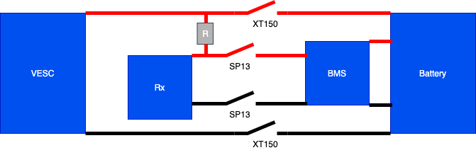
What do you mean with “from bms to rx”? You need to connect the resistor from battery/bms to the VESC input, in order to charge the capacitors before you plug in the main power wire. At the same time, you can use the BMS output to let the receiver read the BMS output and tell you on the remote if everything is OK. But thats two different and separate paths. I only put the resistor on the BMS as this was easier to solder and the resistor fit nicely into the housing of the connector.
I think a few more details on the receiver would be great (particularly since I’m not an Arduino expert). I’m gonna try to order the PCBs next week in the UK. But I can see some cool features like the ability to turn on the power via the relay.
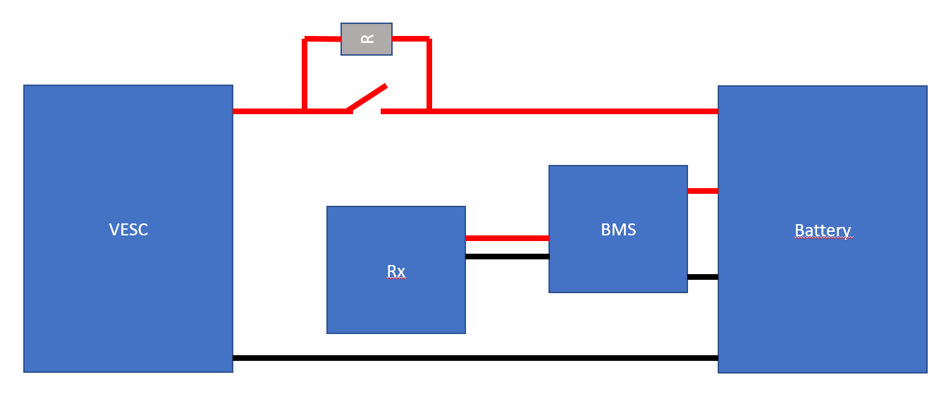
But there is something I don’t understand on the first drawing. In my understanding we have to pre-charge the capacitors on the VESC. Shouldn’t the resistor wire from the BMS be connected directly to the VESC after the main power connector of the positive terminal on the second diagram also?
Like this:
So you plug the negative XT150 in first then the SP13, wait a bit and connect the positive XT150. If this is not correct, please let me know and I will start another thread.
 ! The best think is probably to order 5 to 10 and keep 2 for personnal use…