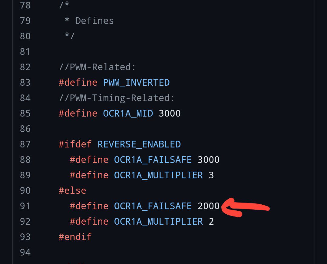
where do I change the failsafe to 100ms? I see it on a few different tabs and on a few different lines in the RX file?
Also regarding failsafe, when idle and my BREmote off my BREmote receiver seems to be send vesc pwm that applies brakes to my motor, drawing ~ -3amps. Switch on the BREmote and the idle is perfect, 0 amps.
Is the fix BREmote or vesc settings?
Thanks that fixed it! ![]()
![]()
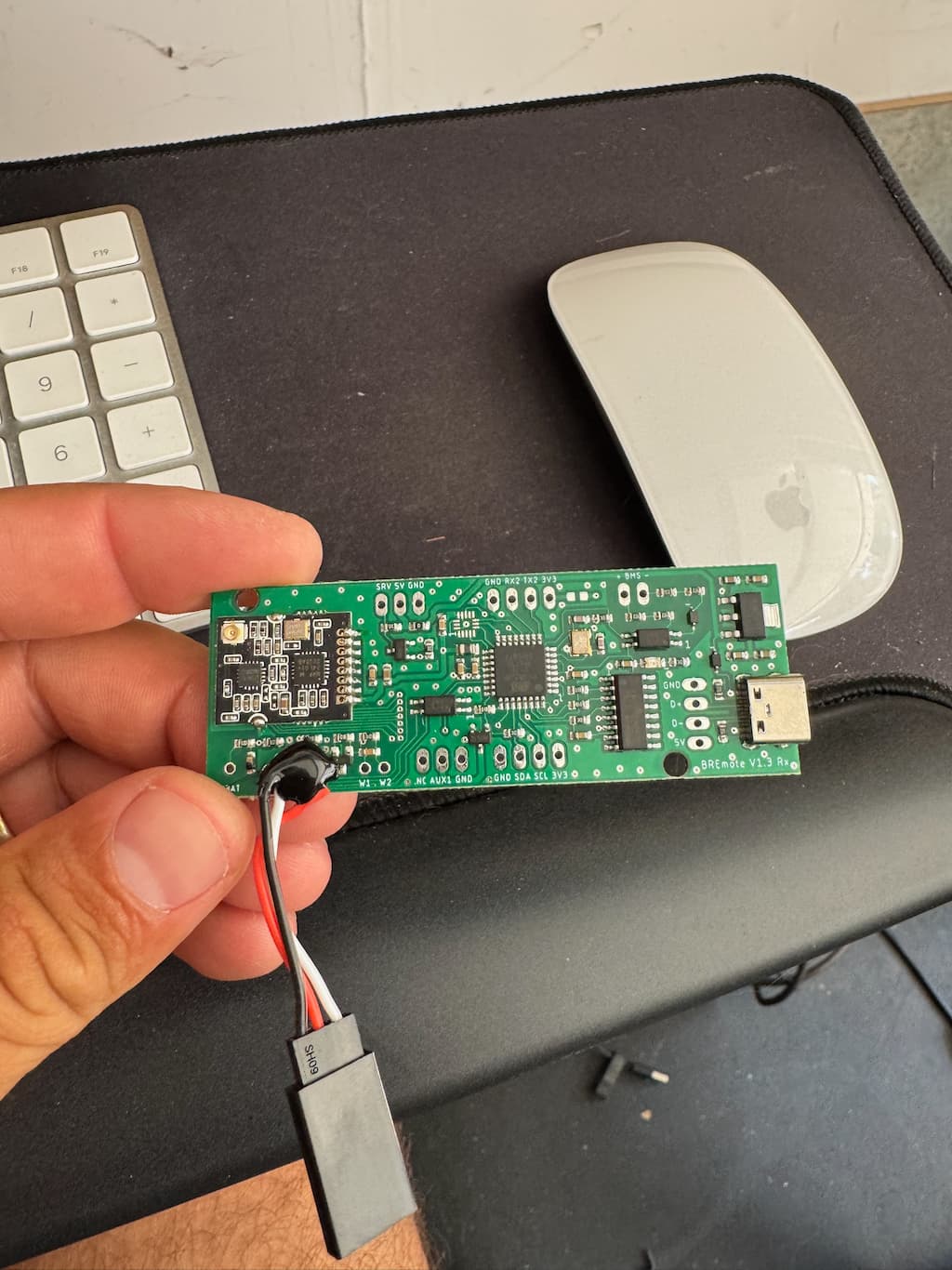
ps I lost my water sensor that was supplied with my BREmote.
I was planning to use of these resistor boards–see any issue with that?
You can just use the sensor board without the electronics.
That’s my plan! ![]()
![]()
1 Like
@ludwig_bre, Thanks a lot for for your work !
I especially like the simplicity, the fact that it is 3d printed and open source, the levels of power and the lock system.
I followed your videos to build and setup the tx and rx. I found it very straightforward.
I made my 1st tests on the water and I have a question regarding the control of the throttle and the curve control.
The first level of power L0 :
- applie 10% to the full curve (output) ?
or - limit the input to the first 10% (and then L1 to the first 20% …) ?
On the second case, I could use the curve control of the VESC remote app to fine tune the levels of power.
On the first case, is there a way to modify the setup of the 10 levels of power ?
Sorry, if my question is not clear enough, langage issue !
1 Like
L0 means full throttle on the remote = 10% on the VESC.
If you do not like the gears, set start gear to 9 and enable the no_gears feature in the shared config
1 Like
Thanks for the answer. I do like the gears a lot ! I will then start at gear 4 or 5.
I am sure this answer is somewhere, I tried reading through the thread, but didn’t see it.
For the BMS input on the Rx board, what is it expecting the signal to be from the BMS? Would it be easy to point me to where to connect it to on the BMS I have? I am just using the BMS for charging, but it would be great if it could detect low cell voltage and get picked up by BREmote. I am using Flycolor X-Cross, so it can’t help with that, as far as I know.
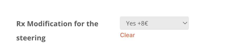
Second, I bought the BREmote with diff steering kit, there is already a PWM connector attached to the board, do I still need to wire in a separate 10k resistor?
Thank you!

For the BMS, just connect the output (in your case charge connector) right to the BMS input on the RX. The RX just monitors, if a voltage is given out or not, so when the BMS shuts off the output the remote generates the warning.
I think if you did not request the 10k resistor to be added specifically you will need to add yourself.
I think I did request the modification, I just can’t tell if they put a little 10k surface mount resister under the blob of epoxy (but I suspect they did).
1 Like
Thanks for asking this, I had the same doubt/question.
Yes, with this modification the resistor is added under the blob an you are ready to go ![]()
Would would cause failure of my BREmote to wake up/turn on?
It happened a couple of times–where I needed to try about five minutes or fifty times before it would turn on.
If you haven’t tried, re-calibrate the BREmote. I’ve found that it takes a little use to get the toggle broken in and if the magnet has shifted at all it can throw off the calibration.
2 Likes
Thanks, good idea. Your theory may be spot on as I am guilty of having adjusted the side tensioning screw after originally calibrating. Fingers crossed. And cheers!
1 Like
Hey guys,
Short but important information for everyone building a LR remote the following days
We have had 2 customers experiencing a problem where the connector of the antenna becomes partially disconnected during the foam filling process, which leads to insufficient range and bad connection.
I will try to find a solution asap, one idea is to add a bit of epoxy on the connector before installing the PCB to the housing.
I will keep you updated and hope you can wait until then with the assembly of your remote.
Sorry for the inconvenience!
6 Likes
A dab of hot melt glue would suffice? It’s just for sealing/fixation purpose.
1 Like