That’s because the 2nd output has no failsafe timer once the signal cuts off - only the main channel has
You can turn the main channel failsafe timer down, then both channels will stop early
For that, change
if(millis() - last_packet > 2000) in line 65 of Rx.ino
Change the 2000 to something smaller like 500
I’m just about to print the parts for my BREmote and have two questions. First is if the main-body-parts for the long range version are oriented correct for printing? Second question is if there are any stl-files for the magnetic connectors that I saw previous in the thread?
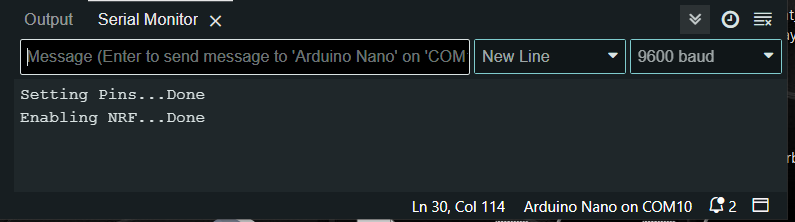
First time Arduino user here, I’m following the setup video at https://youtu.be/RKn8jVGVD6g?si=XRxZ171Mk-YHZTyO&t=1669 . I’ve successfully updated, compiled and uploaded SHARED_CONFIG, but after that when I return to the Serial Monitor I’m getting these 2 lines which is the same as what I get when first plugging the Rx in, but no further messages in Monitor. Is this an issue? Do I need to get more response from the Rx before moving on?
The 2nd motor will always have 0 failsafe as the generation of this signal depends on the Rx process…
But you can set the 1st Motor to something small like 100ms to basically make it imperceivable
I’m not at that stage of connecting the Rx & Tx yet, just connected the Rx via USB as following the video. I’m just about to connect the battery. I’m at 27:50 of the video.
Thanks, It’s all done! I’ll need to get a bit more foam as mine didn’t make it out of the holes in the base. I got a hell of a fright when soldering the battery and the vibration module activated. The extra shroud guard on the LR version made for an extra tricky assembly but I worked it out eventually. Thanks, it was a fun Saturday night for me!
I just configured a motor and VESC and paired with new BREmote but the remote is not showing the correct VESC voltage–it shows 85 when my battery pack is currently at around 53v. What could cause this?
My error, I uploaded the receiver side-code into the BREmote. Fix it by uploading the TX side code but now I have E5 on LED displayi indicating calibration needed. When I upload the calibration I get this message on the terminal, any suggestions?