Ludwig flashed the bootloader to the controller for the kits he made for the german speaking group. If the pcb was odered directly from a manufacturer, one has to flash a bootloader, see here: https://github.com/Luddi96/BREmote/tree/main/Source
2 Likes
Could be a problem specific to the arduino ide version you are using. I remember having difficulties burning a bootloader to a nano, it finally worked with ide 1.6.11 (old bootloader).
Didnt realise you could do that, thought the board needs a bootloader flashed before usb functionality is possible, I’m really out of depth here so making assumptions.
Im gonna try downgrade to 1.6.11 like sat_be suggested and see if that works, if not ill try with usb, but you cant use that method with the TX.
Thanks for the suggestion ill give it a go and report back
Nope I downgraded the software to 1.6.11 and get these:
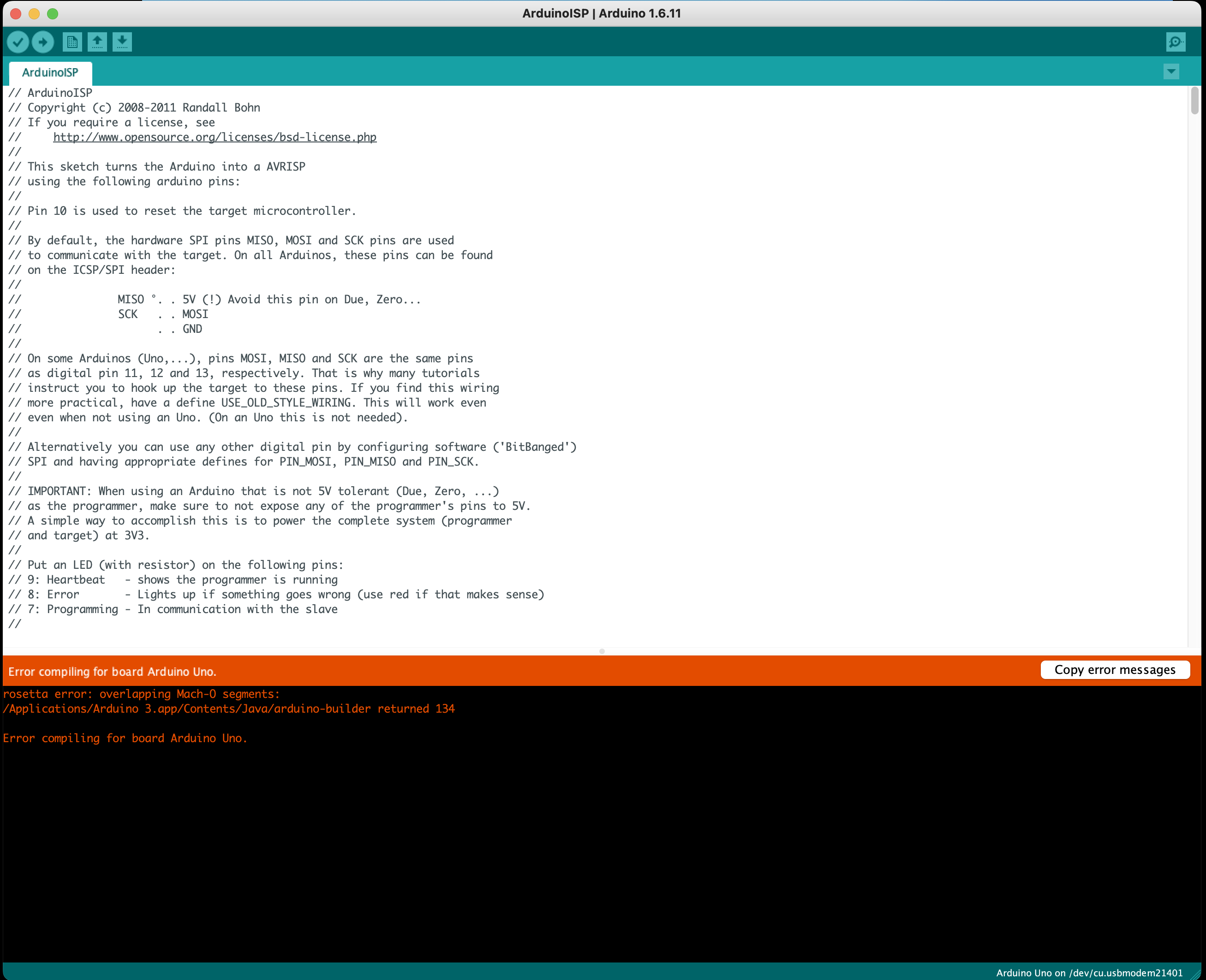
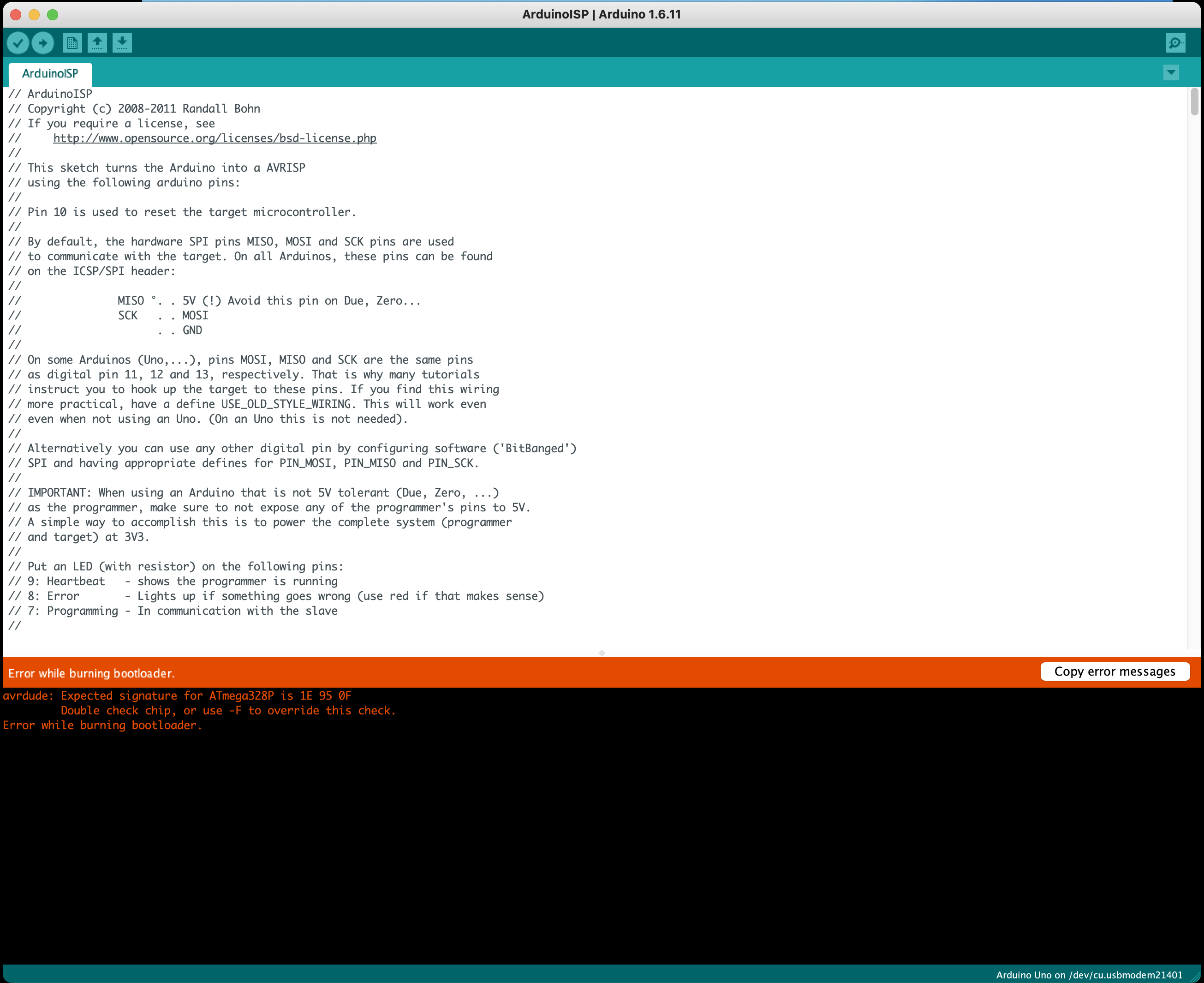
Is it possible that the Uno i am using has an ATMega8U2 chip and the Rx/Tx uses the ATmega328P and you cant use a different chip to flash a bootloader to another? I know nothing about this stuff, I just try follow the tutorials step by step but their is not much info on the “flashing bootloader” part.
As @sat_be already clarified, when the board is fresh from the manufacturer, the ATMega is empty. To enable USB capabilities, it needs a bootloader initially. For you, @Toto44 I did all that work already. But everyone else needs to once flash through SPI…
Can you try this Bootloader Flashing Tool?
It’s standalone, so just upload to the black Arduino and open Serial Port so see what happens.
If it does not work, contact me privately, then we will solve the problem and write the solution here to keep the thread readable ![]()
Really appreciate your help, I will try the tool now.
1 Like
Short update:
@freefoil and I were able to solve the problem.
The main problem is the voltages: While he used the 3.3V to supply the Rx Board, the Arduino still uses 5V on the data lines (Pins 10 to 13). While this can work, using a 3.3V modded Arduino or level shifter is the safe idea.
The device signature reported was always different, which means there was bad communication.
By trying a few times and touching the board with his fingers, he was able to flash the bootloader.
For anyone else trying this: Place some resistors (100 Ohms - 1kOhm) in the 4 data lines or use a level shifter or a modified Arduino. It is also not known if the 5V may damage the accelerometer IC which is also on the SPI bus at all times and only specced to 4.2V.
There is a quite good tutorial how to modify the Arduino: 3.3V Conversion | Arduino Tips, Tricks, and Techniques | Adafruit Learning System
2 Likes
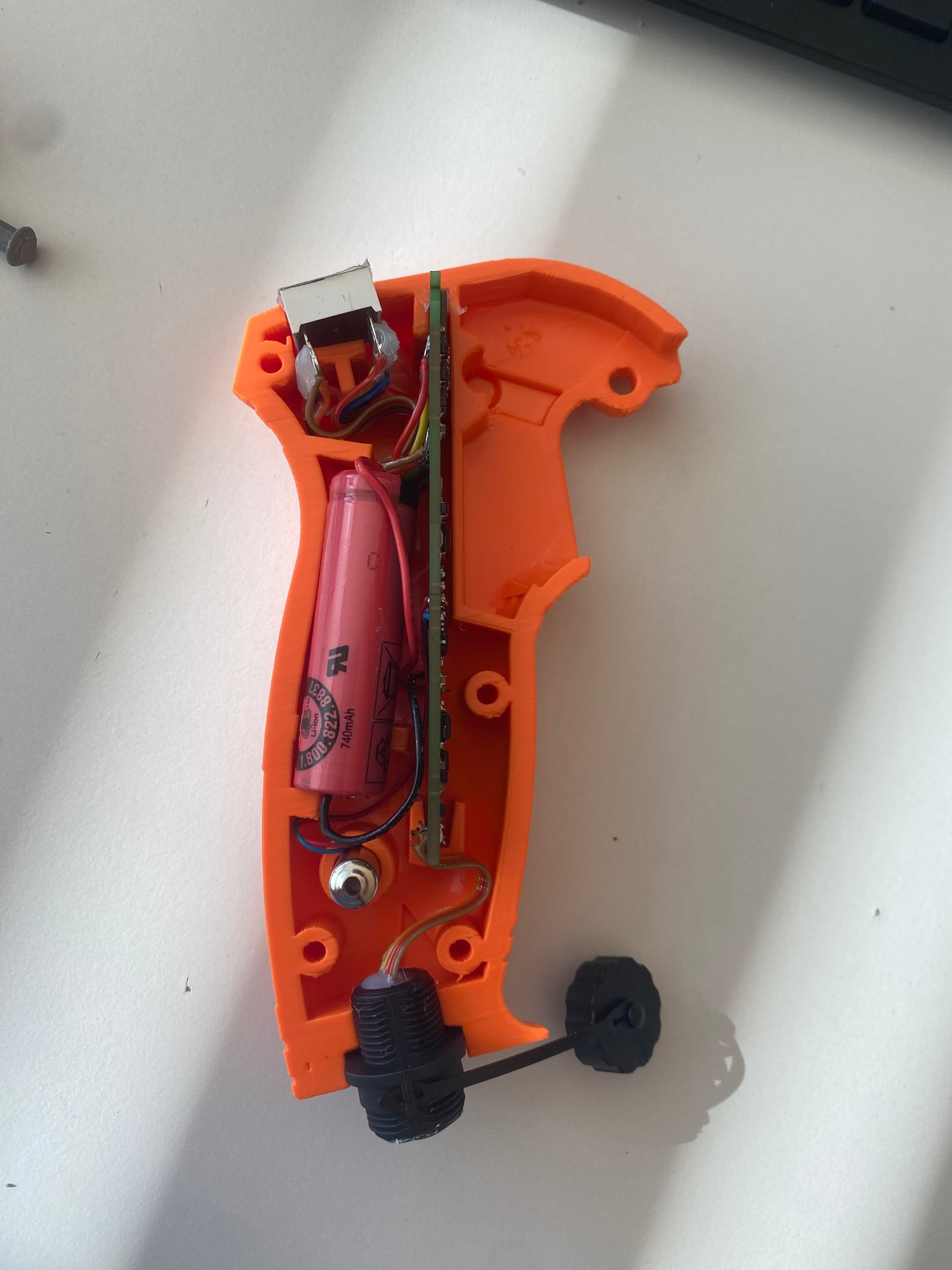
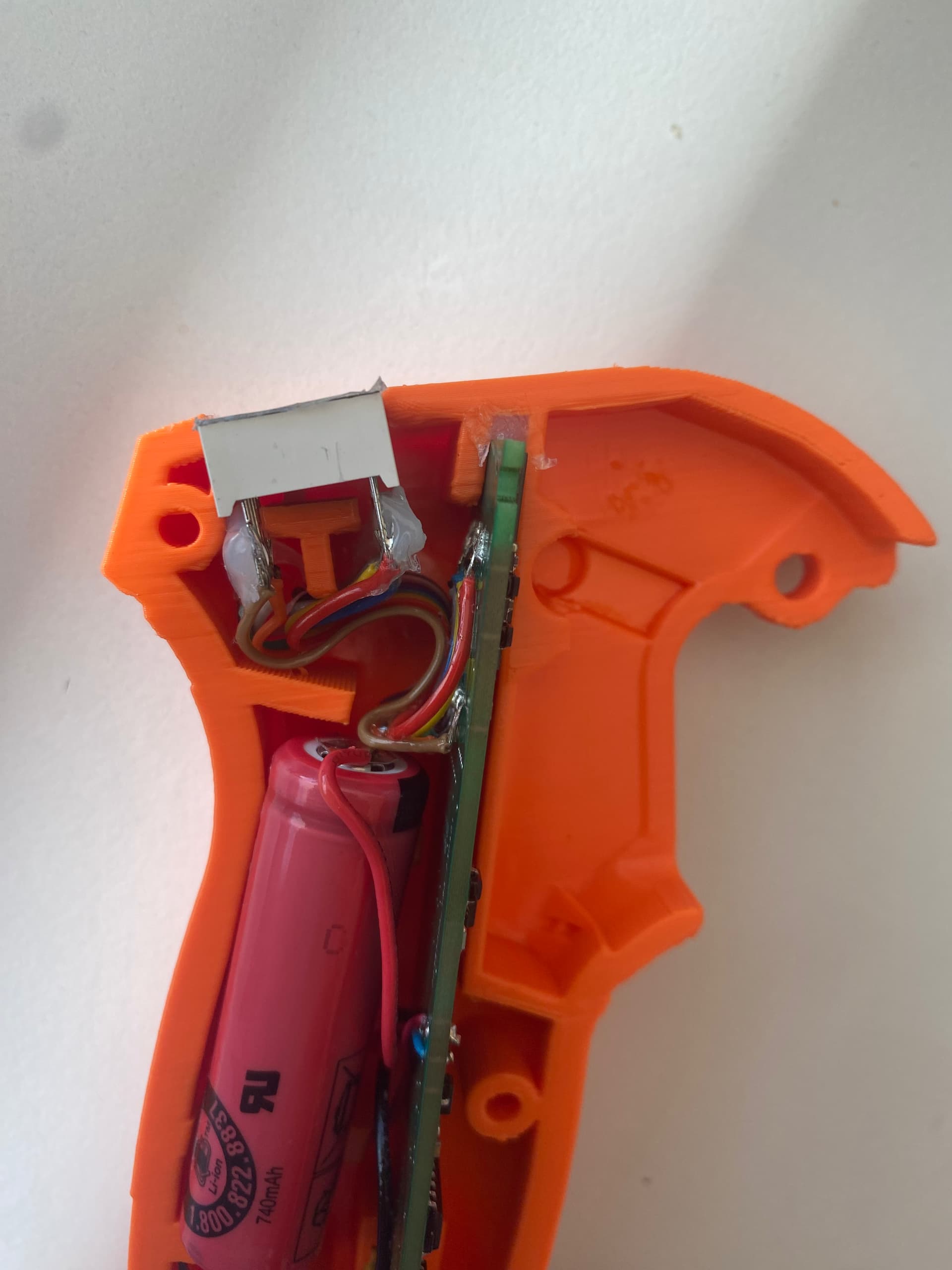
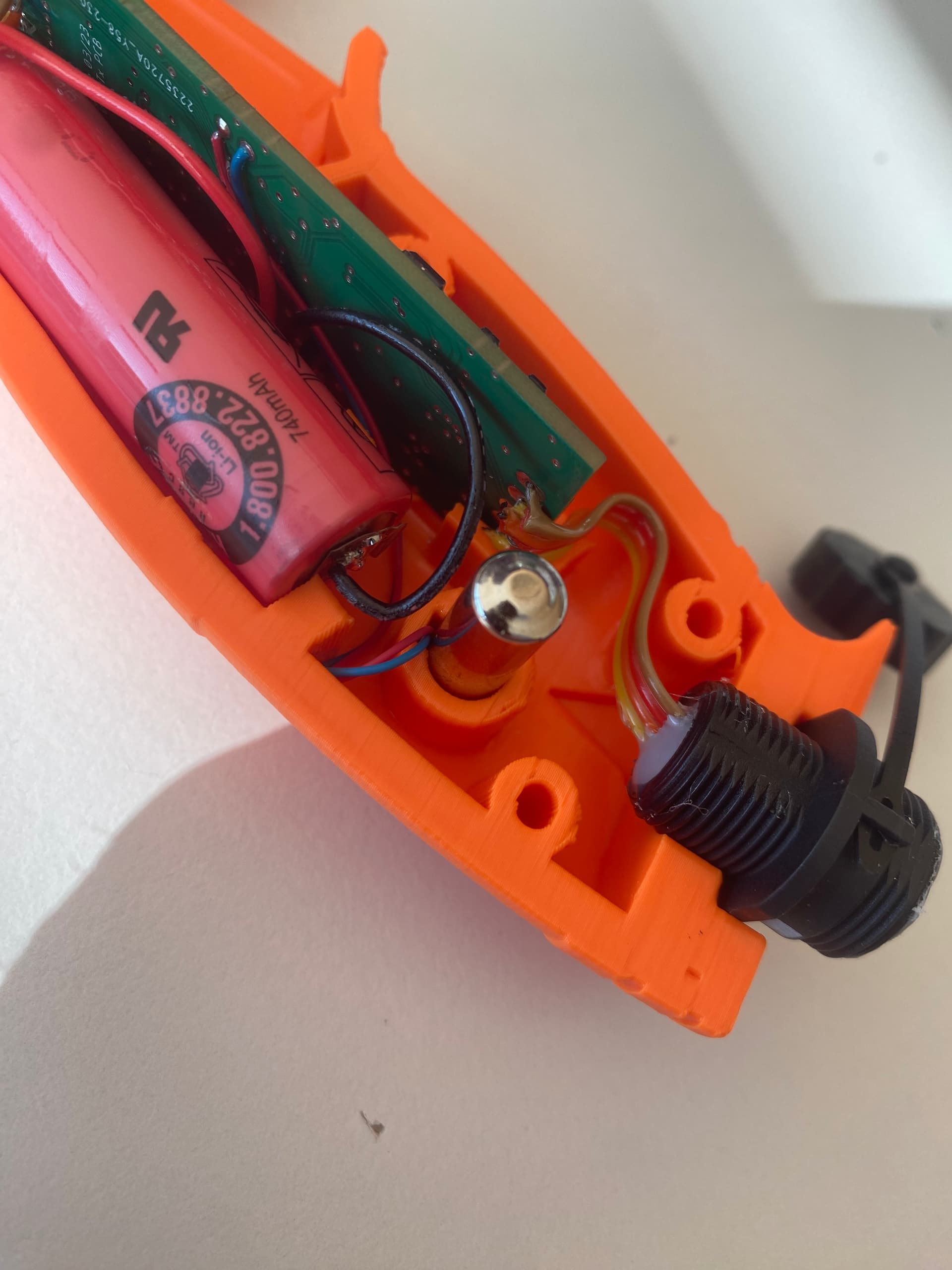
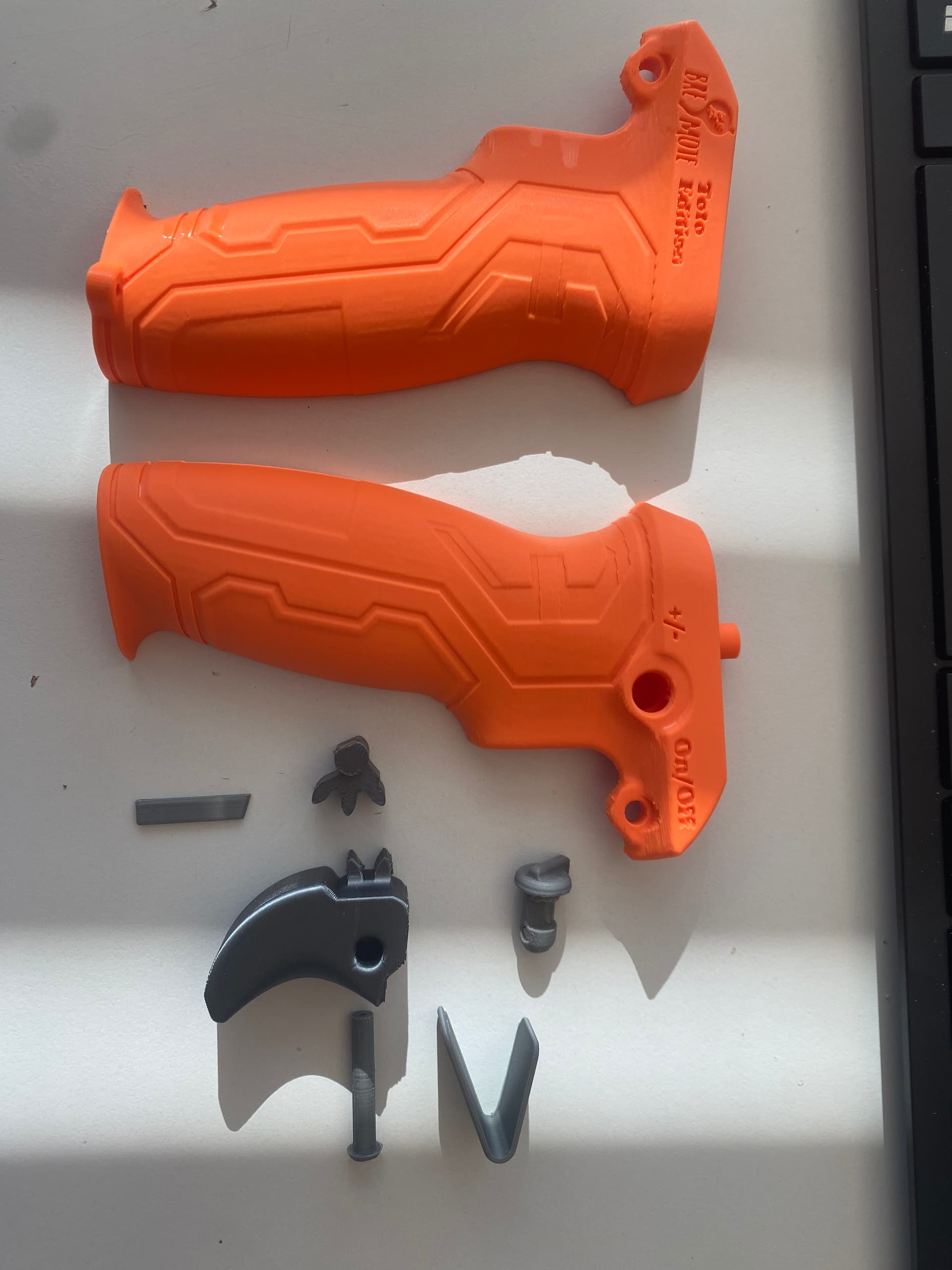
@Toto44 Curious about the working of your 3D housing for the BRemote. Can you share a video or inside picture from the model?
On the Cults3D page (link above) you can see images from inside and outside
Another Update:
On top of the steering with a servo, I have added differential steering capability to the Rx firmware. That means you can connect two seperate VESC + Motors and steering will be done by slowing down either motor
Still experimental, if you are interested, contact me via message.
10 Likes
I have ordered the BREmote PCB’s and have extras if anyone in the US is looking to build a BREmote. I also have some extra magnets, displays, NRF modules both long range and standard range and a couple 14500 batteries. I am just looking to sell them for exactly what they cost and will ship in the US. feel free to message me direct.
4 Likes
I’ve used my bremotes for a good number of sessions so far. I wanted more spring pressure for the toggle, so I reworked the toggle spring, so that it sits in the down position and can only pushed in the standby/power direction.
I would advise against using PLA for the springs, they soften if you leave them in the car. PETG works fine.
I had some issues with the force required to turn on the remote - likely related to the lower grade magnets I’m using. I’ve been informed that different hall sensors are used in the bremote for powering on vs powering on. It’s worth knowing that you might need to change these two settings independently (and I didn’t understand what the STB was referring to - power on from standby):
#define TOG_DIFF 10 //Hysteresis for Toggle (switching the power off)
#define TOG_STB_DIFF 8 //Hysteresis for Standby Toggle (switching the power on - while remote has been in standby/off)
I needed a lower value for TOG_STB_DIFF to allow it to turn on easily. When TOG_DIFF and TOG_STB_DIFF were the same value, it would either turn off too easily or be too difficult to turn on.
I’m having an issue with the display glitching, due to a poor connection with the pins into the sockets. The display sits at a bit of an angle to the sockets, and I’m guessing water might be getting into the sockets. I can give the screen a push and it fixes it, but I wonder for how long that’ll work in saltwater.
I really like it overall. Trigger precision is ideal. Light in the hand, comfortable, and it floats well.
4 Likes
So, is this 5v to 3.3V conversion something everyone needs to do to their bremote arduino?
I got a preflashed one from you but will need to program it after the build as usual.
How are the vesc’s connected to the receiver? Will I be able to read the remaining capacity of the battery pack when using differential thrust?
First VESC is connected to ‘original’ PPM out of the Rx.
There is an unused optocoupler on the Rx, that can be used to generate a 2nd PPM signal, that goes to VESC 2.
UART of one of the VESCs (the one the ‘original’ PPM is also connected to) can be connected to get voltage of battery and temperature. Only of that one VESC however.
I will send you a connection example.
2 Likes
Yes, it is highly recommend to flash the BREmote PCBs with a 3.3V programmer, so either 3.3V Arduino or Level Shifter. Or wait a few weeks until BREmote kits will be for sale officially.
1 Like
How should resistors be connected, in series with the programming wires?
could you draw a simple sketch for us? I don’t want to buy a level shifter or convert the arduino, but i have resistors at hand 