Hi @ludwig_bre in the USA I cant find any source for d3x6mm in N52 grade. I guess metric is not that common here to start with, but even D 0.125 x 0.25 I can only find in N42. The best I can find is D3x6 N42.
Will this work?
If anyone has managed to source the correct spec here in the US please share.
Thanks @Ranelson93 for the link!
Regarding the grade, I would strongly recommend to use N52.
Using a lower field strength means less accuracy / resolution on the remote.
This may influence throttle sensitivity and even more the function of the on/off/gear/lock - toggle switch.
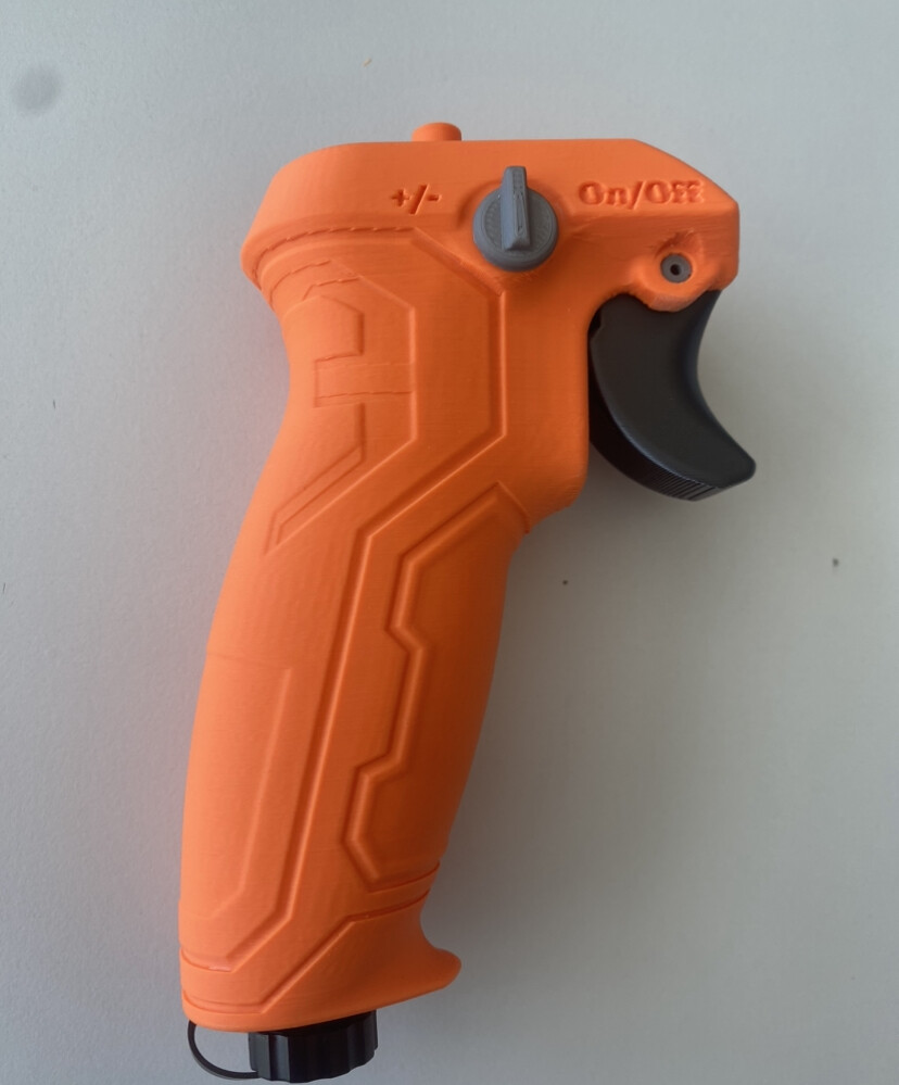
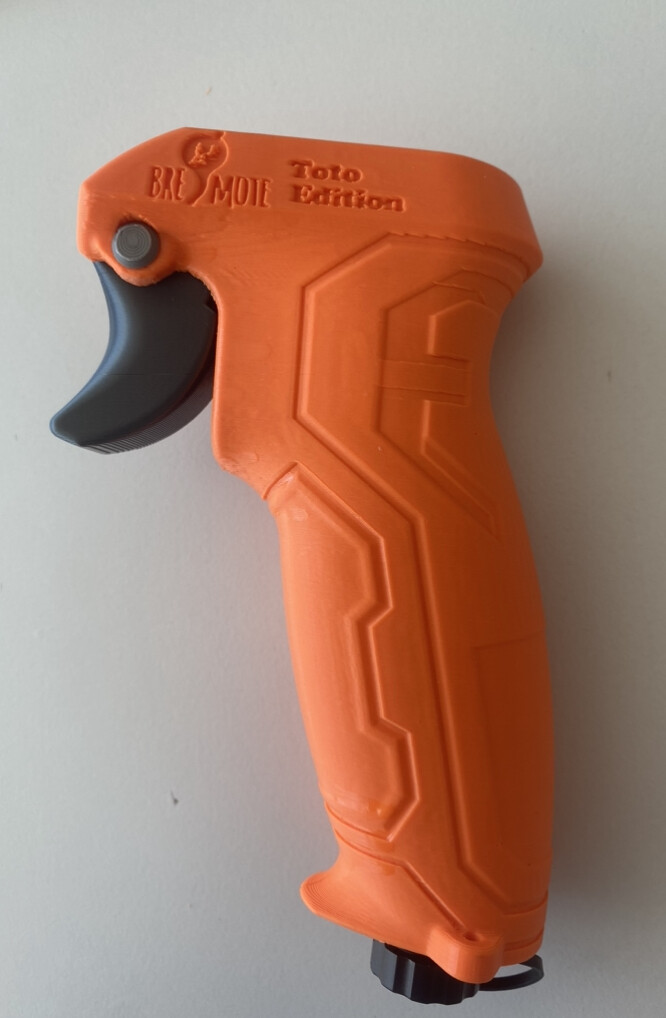
I remixed the toggle button with stiffer springs, so it pops back to centre more positively to reduce the likelihood of accidentally turning it on. The original toggle button and springs takes some careful sanding to avoid stickiness.
Also designed a simple clip/holder to mount the bremote on 1" square aluminium on my tow boogie.
The bremote worked well for a tow session today, the original bremote has a noticeably longer range than the erayfoil. And it floats well. Good throttle lever feel.
I would suggest using a sealant such as bostik isr 70-03, or any other viscous glue, to stick the magnet rod covers into the insides of the top structure. I used epoxy as recommended, and it was too runny, which allowed some foaming glue to make it’s way into the magnet rod area.
With regards to the quantity of foaming glue, I needed to completely fill the ‘tool’ cup/plunger - a good 5mL of each of the 2 part liquid foam. My first effort didn’t produce enough foaming glue to fill the entire remote, which is a problem because you want it to be contiguous throughout the remote from one end to the other.
With more testing and software tweaking, hopefully it’ll be a good reliable workhorse. I would prefer if the square end of the magnet rods should be a bit more beefy where it mates with the toggle/throttle, for robustness. I now have a couple in regular use, we’ll see how they last.
I would prefer an 18650 battery for longer run time, that was the one good thing about the erayfoil. What’s the typical mA current while in use on the bremote.and while turned off?
The range and throttle response is really good, and it sits very comfortably in my (large) hand with the middle angle throttle.
Hello. I designed a different housing for the Bremote electronic.
The only thing you need to take care of is the the small display needs to be soldered by wires to the pcb.
‘Printed in ABS’ is not the most common material to print, so spring properties could vary too much when printed in PLA+, PA or PETG. Maybe some trail and error is needed here when building this housing and adjust for material and personal feel/experience. Should be no problem.
Do you have a picture of the trigger/spring mechanism? There is some kind of switch/lock on the side of the remote housing as well?
The remote usually uses 20mA so the 14500 cell with 700mAh should last a good 20-30h on-time.
Off-current is 5uA (0.005mA) so also a long Standby life (multiple years)
I get this message when trying to flash bootloader to the receiver:
avrdude: Expected signature for ATmega328P is 1E 95 0F
Double check chip, or use -F to override this check.
Failed chip erase: uploading error: exit status 1