Already got an idea how this is going to be powered and waterproofed?
1 Like
Not really, just wanted to see if it works.
Since it can be anywhere, for now I’d just put it in a vacuum bag and stick it to the board.
Also not sure if I want the display or not.
Display will likely drain quite a bit of power.
Without display, could probably use one of the small pouch cells to power it and this would be a tiny package, like 30x30x8mm.
1 Like
Also still have the plan to create a throttle lock for getting up on board at some point, could combine the two functions.
Add a small pressure triggered switch on the board and as long as it’s pressed, throttle gets locked so you don’t have to hold the remote while getting up. Once you let go of the switch , you have X seconds to get up and reengage the remote.
1 Like
Had some additional thoughts about RTM/Follow Me. I think the current “hold the trigger” safety gate is useful as a dead-man switch, but it is not sufficient for Follow-Me safety.
If the buggy is following behind the rider, the rider may not see or hear what it is doing. In that case, holding the trigger does not mean the rider has real awareness or control. It only means they are still authorizing motion.
A stronger safety model would be either:
A stationary operator holding the TX and watching the buggy (i.e. TX GPS speed<2km/h), or
A very-close proximity mode where the rider can notice problems (i.e Distance < 50m) , or
A “ride-ahead” mode instead of Follow-Me.
The ride-ahead idea: instead of targeting the TX position, the buggy could target a virtual point calculated from GPS course-over-ground, for example 30 m ahead and 8 m to the side of the rider. Then the rider can actually see the buggy and monitor it.
The trigger should still remain as a hard stop, but I would not treat it as the main safety gate for Follow-Me unless the rider can actually observe the buggy.
I like this! and not hard to do once FM is implemented! by tweaking FM mode variables or just adding a Front/Ahead option F4. (In addition to the positions I am working on 1- Right Behind (“F1=Right”); 2- Behind=F2; 3- Left behind (F3=Left); and new one F4 (Front). Then, user changes the variables in WebPage such as follow me distance, Angle, and Slow down bubble (to protect the surfer from being hit… in theory.
(perhaps the F4=Front would have a 2x or 3x distance hardcoded… for safety).
1 Like
Hoa about this one?.. Nice screen easy to access GPIO for expansion, no touch screen, fully documented by waveshare and clone avialable in Aliexpress.
ESP32-S3 1.69-inch IPS Touch LCD Display Development Board 240×280 ST7789V2 SPI Display Module and 6-axis Sensor for Arduino
here is the wiki for docs from waveshare.
i may get one to play with, and use as telemery and logger connected via BT to TX.
This needs to be fully potted and add magnetic pogo USB connector as well as waterproof some micro switches, all inside a 3d printed housing. Or it can live inside my transparent lid [Seahorse cas.] (Seahorse SE57 Micro Hard Protective Case – Official Seahorse Cases) on the Tow Buggy.
As I said I already have this working.
If you really want, you could use that module.
But this - https://de.aliexpress.com/item/1005009851781465.html - and something like this - https://de.aliexpress.com/item/1005008990042464.html - is all you need.
For me your’s would be far too bulky to have on me or on my board. Also I assume the power consumtion is pretty hight. Mine comes out at about 30mA in use.
So a 18650 would power it for days.
0.96“ display is really small, maybe ok for young eyes, I can defintely not read anything without reading glasses on such a tiny display.
1 Like
I got the 1.3" one, so far bigger than original Bremote2 display.
Readability more a font size issue than display I think.
Personally prefer smaller total size on my board to a bigger display.
All I personally need to see is battery state and vesc temp, maybe a bar for connection quality.
Think that would be large enough for anyone to read.
If you squeeze like 50 numbers on a 2" display like the VX5 does, I can see the issue.
But easy enough to use a another i2c display if you really want.
The one piece boards are nice though, super simple to set up.
Hi all — two updates today, VESC telemetry and compass steering for RTM/FM.
On the VESC side: what looked like a quick patch turned into a much deeper dive than
planned. A few rounds of diagnosis later, we got there. Root cause ended up being a
hardware conflict — the USB-C serial cable shares GPIO pins with the VESC UART on the
ESP32-C3, cable plugged in during field use silences VESC completely. Underneath that,
two firmware bugs were layered: the GPS UART MUX was taking the channel and never
handing it back to VESC, and a stale error flag was poisoning entire receive windows
from a single bad byte. Both fixed. The good news is the investigation forced a cleaner
MUX architecture out of us — GPS always has priority, always yields when done, VESC
defers properly. Battery %, wattage, and motor temp all live and stable now.
On compass steering: Jan flagged this early and he was right. The motor’s phase and
power wires generate enough EMF to make the compass completely unreliable the moment
throttle engages. RTM and Follow-Me are dropping compass navigation. What I’m doing
instead — take a heading snapshot from the compass at idle, where the data is actually
clean (no throttle, no EMF), then hand off to GPS course-over-ground + PD control once
throttle kicks in. Full PID is overkill for a tow buggy, PD handles it fine. Thanks Jan.
Water test is imminent — aiming for this weekend, next weekend at the latest. RTM
firmware is in good shape and I’m confident it’s ready.
Alpha reminder: pushing updates regularly, always grab the latest before testing.
2 Likes
BLE live on the TX — VESC Tool working (branch feature, not yet released)
NUS + VESC binary protocol over BLE. Connect with VESC Tool (free, iOS/Android) and get live FET temp, motor amps, duty, voltage and RPM from whatever the LoRa link is carrying from the foil. Still on feature/bluetooth, not merged to master yet.
EDIT: Great news BLE testing passed with flying colors !!! Now we have option to turn on BLE on TX and share it to VESC APP and see VESC values, If you do not have a VESC some values will still show up in the VESC Tool Gauges. Will move this feature to MASTER BRANCH, document it in README and push firmware soon.
1 Like
One technical concern from my side before people spend time testing RTM/FM on real hardware: I think the current control logic still has a basic convergence problem.
In my view, throttle percentage should not be used as a proxy for speed. If GPS speed is available, RTM should use measured speed and limit throttle based on heading error, distance, and whether the buggy is actually converging.
A high fixed throttle value while the buggy is still far off-heading can easily produce the wrong behavior: the buggy starts facing away, applies throttle, turns poorly because both motors are already driven, distance initially increases, and the convergence/timeout logic stops the mode instead of bringing it back. Even if it does not timeout, it may oscillate rather than settle.
So before broader water testing, I would strongly suggest validating RTM at very low throttle with explicit checks for heading error, GPS speed, and decreasing distance. Otherwise testers may be debugging a basic control issue rather than testing a usable RTM feature.
Jan, thanks — this is a genuinely useful technical point and worth a
precise answer.
You’re right that the current RTM has no heading-error-proportional
throttle limit. The mode controls steering only (via differential
PWM offset); the user’s throttle passes through unmodified until the
approach decel zone engages in the final meters. Your concern about
the badly-aimed-start scenario is valid: high throttle + large
heading error reduces differential turning authority at the same
moment maximum correction is needed.
A few things that are in the code but may not be visible from the
design description:
- The steering controller is P+D, not P-only. The derivative term
damps the oscillation you describe — it brakes the rate of heading
error change, not just the magnitude. - Phase C convergence check has a ~10s window before it can actually
stop RTM (the first sample at t≈5s only records the baseline
distance; a stop requires the second sample at t≈10s to be
non-improving). Most turns complete within that window. - The approach decel zone ramps throttle from full → 0 as the buggy
enters the final approach, so the arrival is controlled.
What your feedback is correctly pointing at: there is no protection
against the arm-with-high-throttle-while-facing-away scenario during
the initial turn. A heading-error throttle cap — e.g. cap throttle
at 25% while heading error exceeds 60°, release once aligned — would
directly address this. That is a targeted improvement worth adding
before broader testing.
Agree with your recommendation to validate first at low throttle
with serial logging active. That is how this should be tested
regardless.
1 Like
I think the core issue is that RTM uses the same throttle behavior for turning/alignment and for closing distance. Those should probably be separate phases.
When heading error is large, the buggy should first align, not drive forward at high user throttle. On my tow boogie, high throttle leaves almost no useful turning authority, so 70% while off-heading can just make it drive away. Likely even out of range in 10 seconds.
Also, throttle percentage is not speed. Since GPS speed is available, I would expect RTM to cap or regulate based on measured speed, not raw throttle. Otherwise tuning will vary massively between boogies.
So I’d cap/suppress throttle during large heading errors and only ramp it once heading, GPS speed, and distance convergence look sane.
Good points all round — I took this on board and pushed a fix before the water
test. Live now online.
RTM now runs two explicit phases. When heading error is above a configurable
threshold (default 45°), throttle is suppressed to around 5% — enough to power the
differential for steering but not enough to drive the buggy away. It pivots toward
you first. Once heading error drops below the threshold, the run phase engages.
In the run phase, throttle is governed by GPS speed rather than raw user input.
There is a configurable target speed (default 4 km/h for first tests) that acts as
a ceiling regardless of the buggy’s motor or prop setup. This should also solve the
cross-boogie consistency point — the same config should behave the same on
different hardware.
One side effect noticed: during the align phase, motor current is near zero,
which means compass EMI bias is also minimal. So on builds with a BN-880 compass,
the hybrid heading mode gets cleaner readings exactly when it needs them most —
during the initial turn. This is a nice property of the phase separation rather
than anything we designed explicitly.
Both thresholds are configurable via the WebUI under the RTM group. Will report
back after the first water session.
Support monterman (support dev here)
2 Likes
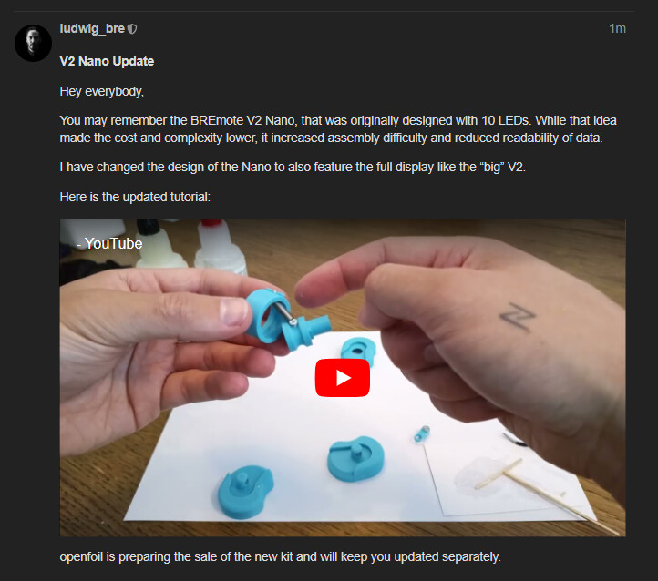
Update on the topic from above: Nano with Display instead of LEDs
See the post on the main BREmote V2 discussion: LINK
2 Likes
Hi,
I am building a tow boat with a Pixhawk 6C, two VESCs and differential thrust.
My current setup is:
• BREmote transmitter with GPS carried by the rider
• BREmote receiver on the boat
• Holybro M10N GPS connected to the Pixhawk for the boat position
I am not planning to use the BREmote Follow-Me logic itself.
Instead, I would like to use ArduPilot on the Pixhawk for my own navigation and safety functions (Follow-Me, geofence, safety stop, etc.).
Is there any way to access or forward the rider GPS position received by the BREmote system to an external flight controller such as a Pixhawk?
For example:
• UART
• MAVLink
• Serial GPS output
• SBUS
• Any other interface
Or is the rider GPS position only available internally within the BREmote Follow-Me implementation?
Thank you.
The follow-me software is still in developement. However to my knowledge it is not planned to make the rider position available to any outside interface. You may request that from @macfly1202 or @monter_man as soon as they have finished their follow-me implementations. Or just add it yourself, since the code will be open-source.
Shoud be pretty trivial to expose GPS via ESP-Now once the software is known working, as they already use the 2.4G stack.
Then use a cheap 2$ ESP32 and forward the ESP-Now data via serial.
No hardware changes needed.
Any of the current AI coding agents should be able to add that in 15-30 minutes.
1 Like
FYI, on my fork, I implemented telemetry forwarding from the GPS to a VESC app. It’s not as good as serial, but it works on the Tx. It could also be implemented via Bluetooth to forward that information received on the RX.