If the box is 100% tight yes
I usually put the electrodes on a vertical surface and 5mm away from the bottom, so a single drop does not immediately alert
2 Likes
Hello Ludwig,
I have 3 questions:
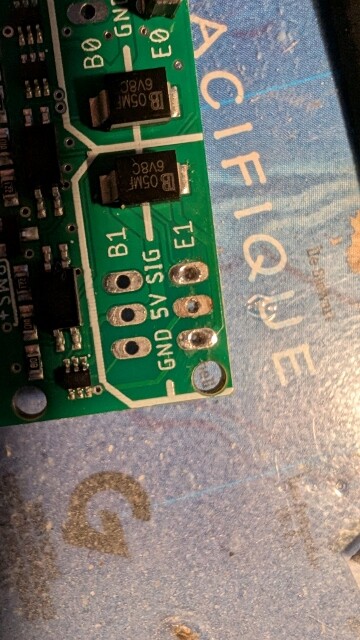
1- I have a short circuit (sparks + smoke) at the level of the 5v on the E1 port of the RX when I connect the vesc (sequre 14200) to the barrels that I soldered.
The welds seem ok, no contacts between the points (verification with a multimeter).
The connection is ok on port E0 with the same type of welding.
Does it come from the PCB or from me?
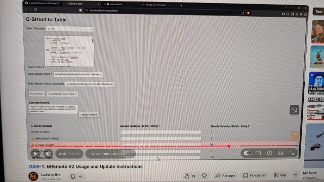
2- I can’t manage to modify the values in my TX and my RX with the “Config tool”, I followed the video tutorial scrupulously.
The values in red of the string 2 do not copy into the string 1 at the end of the procedure: the “Export Base 64 from column2” button seems to not work.
Do you have an idea?
3- The sequre 14200 has one ppm cable and 1 RPM and 1 Telemetry cables: how to connect these 2 cables to the UART 1.0 of the RX?
Thank you in advance.
Please send more information how it is connected, schematic and images
That’s not how the tool works, only what is in column 1 will be exported, column 2 is only to compare
Telemetry is currently only supported for VESC controllers, ESCs cannot be read out
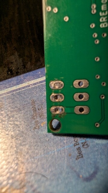
1- some photos.
I don’t understand the short circuit when there is no contact between the gnd (-) and the 5v (+).
I will contact Open Foil to recommend an RX but I would like to understand the problem, I don’t know very well welding on PCBs, I may have overheated the strip.
2-I don’t understand, in your video #009 (cf copy screen), the modified values to be copied are in column 2 (example rf_power: 20), in column 1 rf_power is at 0.
In fact, all the modified values are exported to column 2 and reset to 0 in column 1, so re-exporting column 1 cancels the operation.
That’s not the goal so I’m wrong somewhere.
3- ok, I thought the sequre was a vesc.

Not sure what or how your short circuit happened to be honest
You can try to repair, connect the 3-pin header again, but bridge the 5V pin to the one above (B1)
Connect GND and Sig like normal
Make sure the ESC wire only gives out 5V (make sure there is no problem with the ESC)
Where did the spark or smoke come from? Did you see a specific part on the PCB?
1-The sparks and the smoke come out of the hole 5v
I tested with a 3-pin header on B1, there are sparks at the 5v hole of E1 …
2- solved.
I put the values back in string 1 before applying “export base64 from column 2”
The new values are taken into account in “serial terminal”
Hello
I wanted to say that so far my bremote works very well ! It is a pleasure to use. The issues i had were due to my own shortcomings.
I burnt the Bec board because of a conection mistake, but jasmin sent me a replacement even before I had time to use a sketchy double cheap esc.
It is hard to waterstart behind a tow with the remote in one hand and the bar in the other. I think that an implémented cruise control ( not with speed but with a full power on certain gear maybe) could be useful. It would also prove nice when riding once you have selected the correct gear.
Is something like that possible Ludwig ?
1 Like
Thanks for the feedback
Well, you can just put the remote in a low gear and hold the trigger pressed all the way. This way you don’t need to concentrate on holding the finger precisely, just squeeze tight.
No matter how a cruise control would be implemented, I would always require the user to hold throttle, otherwise this is a big safety risk when you fall and need to actively push another button to stop the craft… Not just let go of everything to stop
1 Like
How is the Nano coming along?
A way to implement it, would be to hold throttle at desired value, push and hold another button to keep that throttle value. Or to select desired throttle, fix with a button and as long as throttle is at or above that level it would stay. That is you can just hold full throttle after.
Both would be possible even with the current remote, but handling that extra button via the toggle would super uncomfortable in use.
Or you could do a failsafe with an additional module as discussed in another thread and have this option just as a “boost function” for a few seconds.
But without any additional buttons anything like that would be hard to use.
It works with the people that tested it
I did not have time to polish the files for uploading to a repo yet
Jasmin from openfoil has everything for the kit in stock and is preparing a sale, just needs a few more days, you will see the update post on the sales topic soon!
Regarding cruise control
Maybe an option:
Throttle to the desired value
Push toggle full right/left very fast and let go again, like a fast button push
→ this will lock throttle and not be read as steering command
You have to hold throttle between 10 and 100%, lower than 10% will disable, also another fast push will disable
I guess most people won’t steer that aggressively, so slow and less than full angle steering maneuver should not trigger the function…?
I think that is pretty close to my second option above.
For me personally, my usage is very basic.
I never use steering with high throttle, probably never above 20%.
It does not seem to do much under load and when just steering the boogie anything higher is pointless.
And I don’t use gears.
So I could probably just implement any toggle movement above 30% as a throttle lock.
Just not sure I would actually be able to enable it in the situations I would need it. Holding a handle in one hand, the remote with the right throttle in the other and then handling the toggle, is quite a bit to ask for my skill level. Don’t know if that would actually help ot just overcomplicate things.
IMO steering is only to get the craft back, while being pulled you steer the boogie by how you pull on the leash
So yes >x% could also work without any fancy detection
Hmm yeah I understand
But not sure where that “new” lock button would be placed to be better accessible than the steering toggle? Or asking the other way, could the shape of toggle be changed/adapted to be easier reachable? I one made one that kind of wraps around the side of the remote, so the thumb can be on the side as well
Not sure, would have to try it.
I was thinking the toggle thing on the Nano would work well.
I have the remote in my hand and push up of the flat part of the palm. Simultaneously handling the toggle with my thumb just feels very hard to do.
Just pushing with the thumb instead of that side to side movement would be much easier I think. Or just pushing with any finger.
But next time I get on the water, I will check if I could actually do it.
1 Like
Hello,
I still have a problem with my bremote.
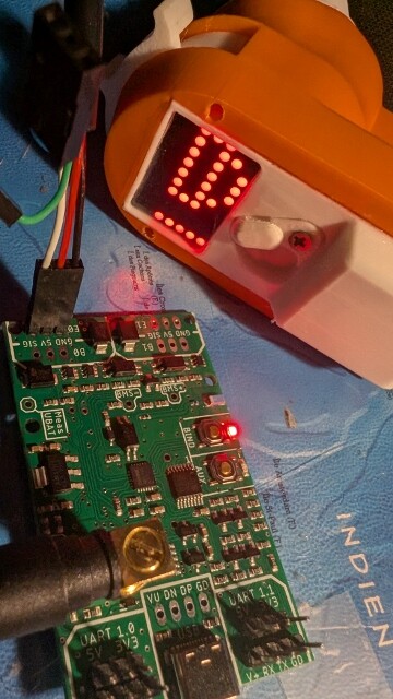
I updated the firmware on the TX and the RX with flashdownloadtool and made the modifications with configtool.
The TX and RX seem to communicate together but I have the impression that there is no signal (or incoherent) sent by the B0 of the RX.
The engine does not run. (except sometimes by random impulse for 1 or 2 seconds without me touching the TX trigger)
I did a printPWM, the numbers of the 2 columns vary at the same time by activating the trigger on the TX…
For the steering, the numbers vary towards the left and right depending on my order.
Another thing, I have a flashing dot at the bottom left of the TX screen
Thank you Ludwig for your help.
You mean B0 or E0?
B0 is the input for a BEC (voltage regulator, optional) while E0 is the signal output to the ESC
That sounds like everything is fine, which value do they vary from / to at 0 and full throttle
Flashing dot means eFoil battery voltage low
Did you select analog voltage measurement for battery and not connect anything to the measurement input?
of course E0, not B0, sorry.
Throttle 0 : value =1101 , 1500
Throttle max : value = 1659 , 1849
I indicated a battery of 13s in the configtool but I use a battery of 12s for testing; that might be the explanation.
Your value for E0 looks kind of ok, I am guessing you set 1100 as min_pwm on purpose?
The 1659 value for full throttle looks like you are not in highest gear on the remote?
How did you calibrate the ESC to the remote? Did you do the full throttle → apply power → 0 throttle procedure? Did the ESC beep like it should?
Do you have any other receiver or servo tester to Test the ESC with?
Maybe
You can send a ?printBat in the terminal of Rx to check the actual measured voltage
PWM0 Min: 1100
PWM0 Max: 1900
Yes, i was not.
i just tried L9 on the remote and the value became : 1900 , 2000
I didnt understood the link between Throttle value and gear.
My esc is the SEQURE 14200 firmware AM32.
I used the configurator AM32.CA
I didnt calibrate the ESC to the remote ; how to do that
I have a remote Flipsky VX2, i tested it with the ESC sequre and the motor works without calibration.
That means it’s probably calibrated to the flipsky remote
Please check the manual or other sources how to calibrate your ESC to the Rx
In short what you have to do
Unplug ESC from power
TX set Gear 9, give full throttle and hold
Plug battery and wait for many beeps from motor
Let go of throttle, so 0, you should get another amount of beeps from the motor
If remote is set to 1100 PWM, it will probably not even arm.
Don’t know about AM32, but blheli32 default is 1000-2000. So if it is stock and uncalibrated, it will not turn on at 1100 minimum throttle.
1 Like