
Did anyone else have this problem? I printed the spring an the toggle from pla (for better spring tension and looks). The rest of the remote is mostly petg. This happened after i tried steering after going straight for about 5 mins so i assume this is an fatigue fail. Since pla fails instantly it just snapped off (luckily i caught it to save the magnets). Is there any room to give it more material in the area next to the magnets?
Does anyone know of a stronger spring size for the throttle I’m finding it too soft. Bit more tension would be nice,
Cheers Astan
Does any FW support using only UART for a VESC on the Bremote V2.0?
Stupidly enough I put the effort in to do some small changes to the VESC FW to support internal pull-up on PPM signal pin to be able to directly connect an emergency/kill switch there. Simply to make absolutely sure that no cable break would disable the kill switch feature.
The only relatively simple pin to use is the PPM pin on the Flipsky 75200 V2.0 Pro I am using. SWD pins are not available which would been a decent alternative (regarding how much VESC FW to change).
Technically the Bremote V2.0 could support using only UART right, but does the FW at this point? Some config I missed?
It currently does not support it.
It could support that for 1 VESC, not for dual VESC due to hardware constraints
However I feel like adding your own pullups to a ADC pin and use that for kill switch would be less work and result in the same
That is exactly what I want to avoid, since it gives rise to a “fail deadly” rather then “fail safe” condition if the pullup resistor connection fails, only internal pullup will be independent of any electrical connection. I have over the years had trouble with that JST connectors and similiar withstand vibration relatively poorly over prolonged use.
Assume I want to add it (for one VESC), I assume it would be sufficient to change RX FW? Where in code would you prefer me to take the throttle signal if I make a pull request? Any other pointers or things to think about?
On another question, I seem to have lost some of the screws for my BREmote V2, one of the shorter (for powerswitch) and the two longer on bottom of handle. Which size are they? I could not find it on github
True, but there are many other things to consider:
For example, internal pullups of the processor on VESCs are very weak, so even a tiny bit of water on that connector will also cause a “fail deadly”.
If you want to have a robust solution:
Either use PWM input, connect with a resistor to Rx. After that resistor, so towards the VESC, use a NO contact kill switch: The NO is connected between Signal and GND, therefore short circuiting the Signal when “KILL”. This is safe to do after the resistor which will protect the output of Rx.
Or use a NC contact, that can be used in the suppy (5V) line of the Rx, so when opened, the Rx will lose all power and also turn off, therefore not delivering any signal. This will also be sufficient current draw where a bit of water won’t have any effect.
You may even combine both or use a relay with NO+NC outputs.
Yes, but the UART connection is not intended for high speed / low latency since it is multiplexed with the GPS for example. You will get 1-2Hz update rate at best, making the throttle feel sluggish. You may find ways around that, but I don’t have any recommendations from the top of my head.
DIN 7982, 2.2x6.5mm and 2.2x9.5mm
Only in the case that the water shorts to a voltage such a 3V3 or 5V. Any short to ground or cable break is “fail safe” (kill switch is conducting when condition is safe and connection is broken as soon as “KILL”). But of course you are correct if for any contact made between 5/3V3 and kill_switch pin will result in “fail deadly”.
I do not want NO. Broken connection is to high risk. I already have a NC (when “KILL” it stops conducting).
Seems like either I have to rewrite more of VESC FW to get another pin with pullup and/or use the kill switch to power the RX unit.
You don’t happen to know what VESC default behaviour is in PPM app if signal goes constant low (no pulses at all)?
VESC has clearly defined loss of signal / failsafe:
No PPM Signal: Failsafe timout (default 1000ms but user-definable), then stop motor (you can define a braking current as well, see the line below Timeout
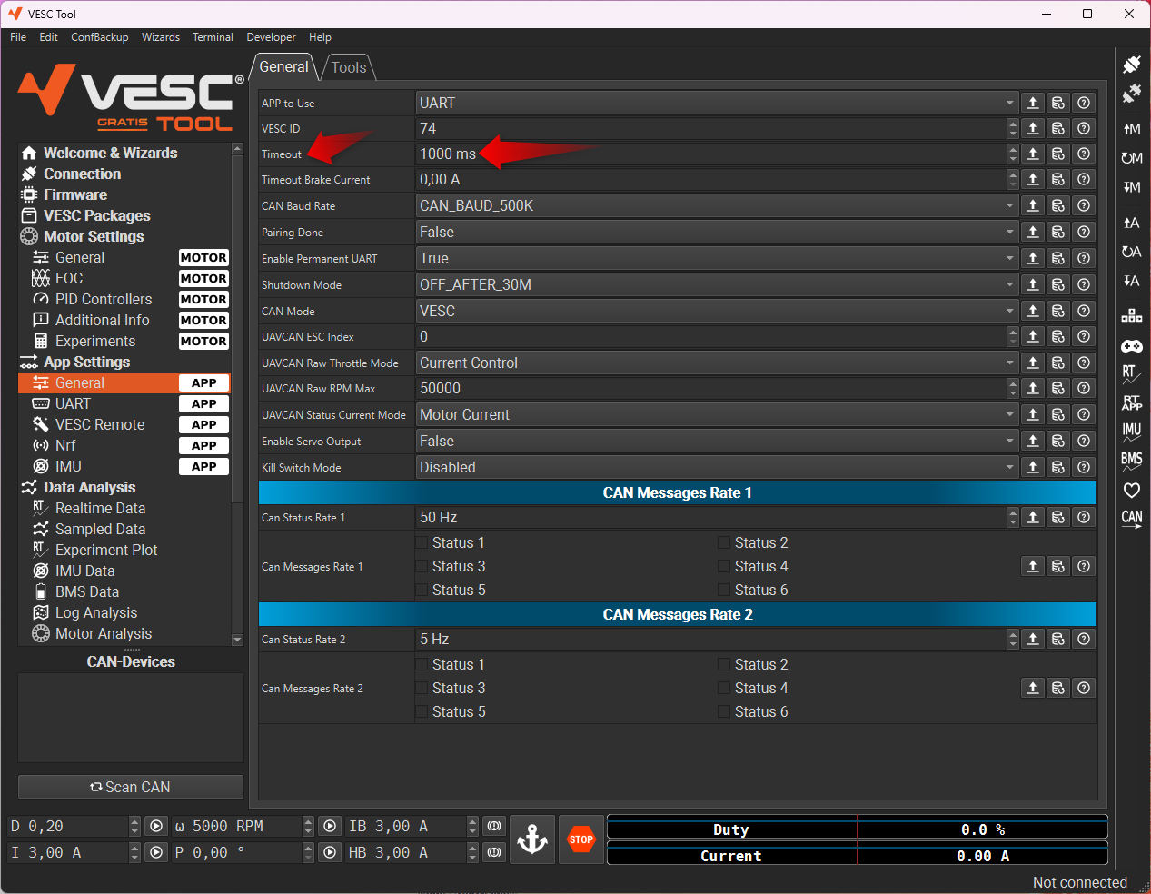
Great, and app to use is “UART and PPM”? Otherwise I won’t get any voltage and so on?
How often does the BREmote send pulses in worst case? 20 ms? Would like really short timeout 
No, just PPM
UART just needs to be enabled (see “Enable Permanent UART” in the image)
Default 50Hz frequency, so 20ms. I would set timeout to 100ms or so, so a few signals can be missed.
Are you sure? I thought that on my VESC (a 75200 V2.0) there is another UART only on the PCB (connected to integrated BLE dongle), when enabling permanent UART it will enable that UART. While the one in the exposed connector remains disabled if no UART app (ADC and UART or PPM and UART or UART) is used?
VESC will communicate on any UART port with whatever peripheral is connected. It does not really reserve a certain UART port for a certain function. While I am not 100% sure when which UART will be disabled, I have had BT modules, BREmote Rx and whatever else connected to all ports so far, never set UART App, only UART enable and it worked.
In the “V1” version both UART were exposed from the 75200 and both worked exactly in the same way. Now flipsky just routed one of them to a BT module, nothing else changed afaik. Definitely not the frimware, since they are still stealing that from another manufacturer 
I just went through the source code, I actually think on the V2 version (and VESC FW 7) it seems like permanent UART option only will enable the internal BT module. I haven’t tested yet so cannot be sure though.
app.c UART config call, second call is the relevant:
app_uartcomm_configure(appconf.app_uart_baudrate, true, UART_PORT_COMM_HEADER);
app_uartcomm_configure(0, appconf.permanent_uart_enabled, UART_PORT_BUILTIN);
UART_PORT_COMM_HEADER will be zero and UART_PORT_BUILTIN will be 1.
Then looking into the Trampa config that Flipsky is using (HW75_300_REV_2 is defined):
#if defined(HW75_300_REV_2) || defined(HW75_300_REV_3)
// Permanent UART Peripheral (for NRF51)
#define HW_UART_P_BAUD			115200
#define HW_UART_P_DEV			SD4
#define HW_UART_P_GPIO_AF		GPIO_AF_UART4
#define HW_UART_P_TX_PORT		GPIOC
#define HW_UART_P_TX_PIN		10
#define HW_UART_P_RX_PORT		GPIOC
#define HW_UART_P_RX_PIN		11
#endif
We will have the UART defines with “P” in it, which will be indexed by one (second entry in array accessed by second call above):
#ifdef HW_UART_P_DEV
#ifdef HW_UART_P_DEV_TX
	serialPortDriverTx[1] = &HW_UART_P_DEV_TX;
#else
	serialPortDriverTx[1] =  &HW_UART_P_DEV;
#endif
	serialPortDriverRx[1] = &HW_UART_P_DEV;
	uart_cfg[1].speed = HW_UART_P_BAUD;
	RxGpioPort[1] = HW_UART_P_RX_PORT; RxGpioPin[1] = HW_UART_P_RX_PIN;
	TxGpioPort[1] = HW_UART_P_TX_PORT; TxGpioPin[1] = HW_UART_P_TX_PIN;
	gpioAF[1] = HW_UART_P_GPIO_AF;
#endif
However it also seems like the UART in the connector (primary UART) only disables if using ADC app and configuring rx/tx pins as buttons. So using PPM app and permanent UART off will still have UART in external connector.
Good to know! Thanks for researching