Ok, then an update will probably solve this, since I implemented a fix already some time ago
Also recommend to update Tx btw, for the newest collision detection features
I was thinking of designing a smaller version of the V2 receiver, better suited for eFoil and assist situations where a 2nd output is not needed and size is a concern
I was thinking if the following
changes towards the “normal” Rx currently available:
No 2nd motor output: I will probably leave a pad somewhere so you can still read the 2nd signal with an Arduino, but it won’t be plug and play with a 2nd ESC/VESC
Simplified UART: One dedicated UART for VESC, one for GPS, fixed ad 3.3V for VESC and 5V for UART
No bind and user button - binding will have to be done via software/USB
SMA antenna connector not assembled to board, making it much flatter, antenna connected with U.FL directly to the RF module/processor
BMS detection input will need external resistors when used (saves a lot of space due to onboard resistors having to be spaced apart otherwise because higher voltage)
Not changed:
Analog voltage input for ESC users
Wetness Sensor
WiFi/BT connection
Same processor/firmware/RF Link: Compatible with all available tools, remotes and equally good water penetration and range
Open questions:
USB C port onboard or with external programming adapter? Would save a lot of space, but also make programming and debugging more tedious
What’s the size/shape you prefer? Preferred measurements for width x height please?
Leave SMA antenna connector as a footprint so the user can assemble themselves? Takes a lot of space though…
Do you even have a need for a smaller Rx? If so, leave a like
USB-C is a nice-to-have, but in foil assist mode I’d completely pot the RX, so a micro cable sticking out would be just fine (whatever is the lighter option I would take)
size and shape: the current Maytech RX is a good size. Square and smallest possible is prob an easy bet
no SMA, U.FL is just as easy. SMA is too heavy for foil assist
Maybe comes with a lightweight potting kit like the BREMote?
Myabe 2, extra 5V pin to attach an LED that shows connection or no connection?
My wishes for a smaller rx:
No bind and user button
antenna connected with U.FL directly to the RF module/processor, no SMA
Leave SMA antenna connector as a footprint : No
no BMS detection i
include a USB C port!
size/shape: can be long, but not to width
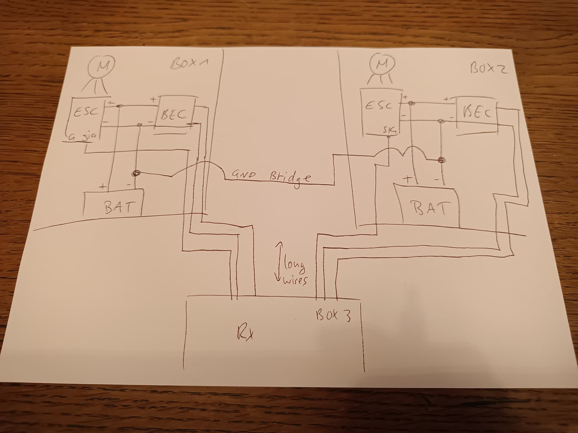
2 ESCs have their GND connected on their power input. A lot of current flows there and since wires will always have resistance and therefore voltage drop at current, the GND potential of those two ESCs will differ from another
The Rx will generate the PWM signal that is only a few volts, in reference to the GND it gets on each channel
If you connect those signal GNDs as well on the Rx side, the voltage difference from the power cables will introduce interference, that may be degrading the PWM signal
So you need a separate supply for each PWM channels with separate GND, therefore 2 isolated BECs
If you don’t use them, expect interference and one or both motors cutting out randomly
If you want to save space and not use the BREmote BEC, just use ESCs or VESCs with integrated BEC, so they can supply the Rx on their own - you will still need 6 wires though, GND, 5V and SIG each
You remember back then, when we had stereo and cassette players, and sometimes connecting them made them hum? Same thing - GND loop (Brummschleife in German)
Another analogy: Take 2 eSkate boards, control them with 2 independent remotes and try standing one foot on each board without having them drift apart in speed and forcing you into a split - that’s how the Rx feels
Thank you for the effort the video and for the electronics education
If I understand it correctly, that means the only way to wire this with two BECs is to put the RX right next to the ESC, which means you also have to put both ESCs at the same spot.
And quite honestly from the video, I still do not get why it has to be two BECs. If the BECs are close together, you also directly connect ground there between the two. Only V+ is separate in that case.
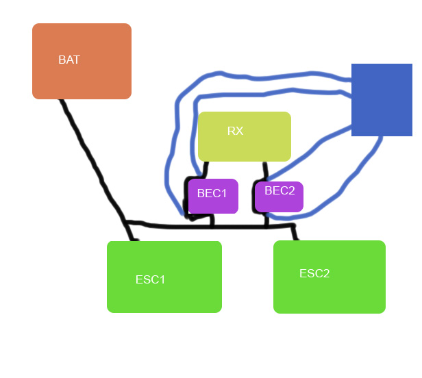
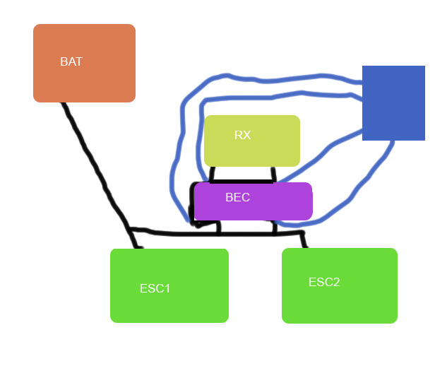
I’ll add two less nicely draw pics. Hopefully you can still understand my question.
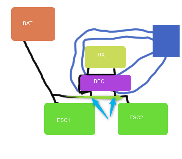
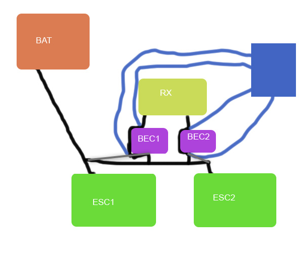
Likely I am missing something there, but I would assume the light blue marked spots should have more or less identical gnd levels. And if that is the case both pics should be near identical regarding a gnd loop.
The closer together I put the BECs the less difference.
If I put the PCBs back to back, the difference would be 2mm of trace on the PCB.
No.
The BECs need to be taking their voltage right next to the ESC, but the wires from that place going to the BEC and from BEC to Rx can be arbitratily long, since they don’t suffer any voltage drop.
Thats nice, but the idea is not to make the BECs not have any voltage difference to each other, but to make each BEC not have any difference to the corresponding ESC, which will get bigger and bigger the further you place the BECs input wire from the corresponding ESC
Maybe do it like on the VESC 75200 with just a connector and an (optional cable)?
On my RXs the USB ports are all broken by now or rather they still work, but they do not provide 5v. I assume those are really tiny pins and close together, so even a bit of condensed water or even salty air will lead to corrosion.
In the current bremote v2 implementation, is there a way to reduce the steering effect based on the throttle/speed?
low throttle/speed → high steering
high throttle/speed → low steering
I would like to avoid tilting over my tow boogie on high speed and still be able to do sharp turns on low speed…