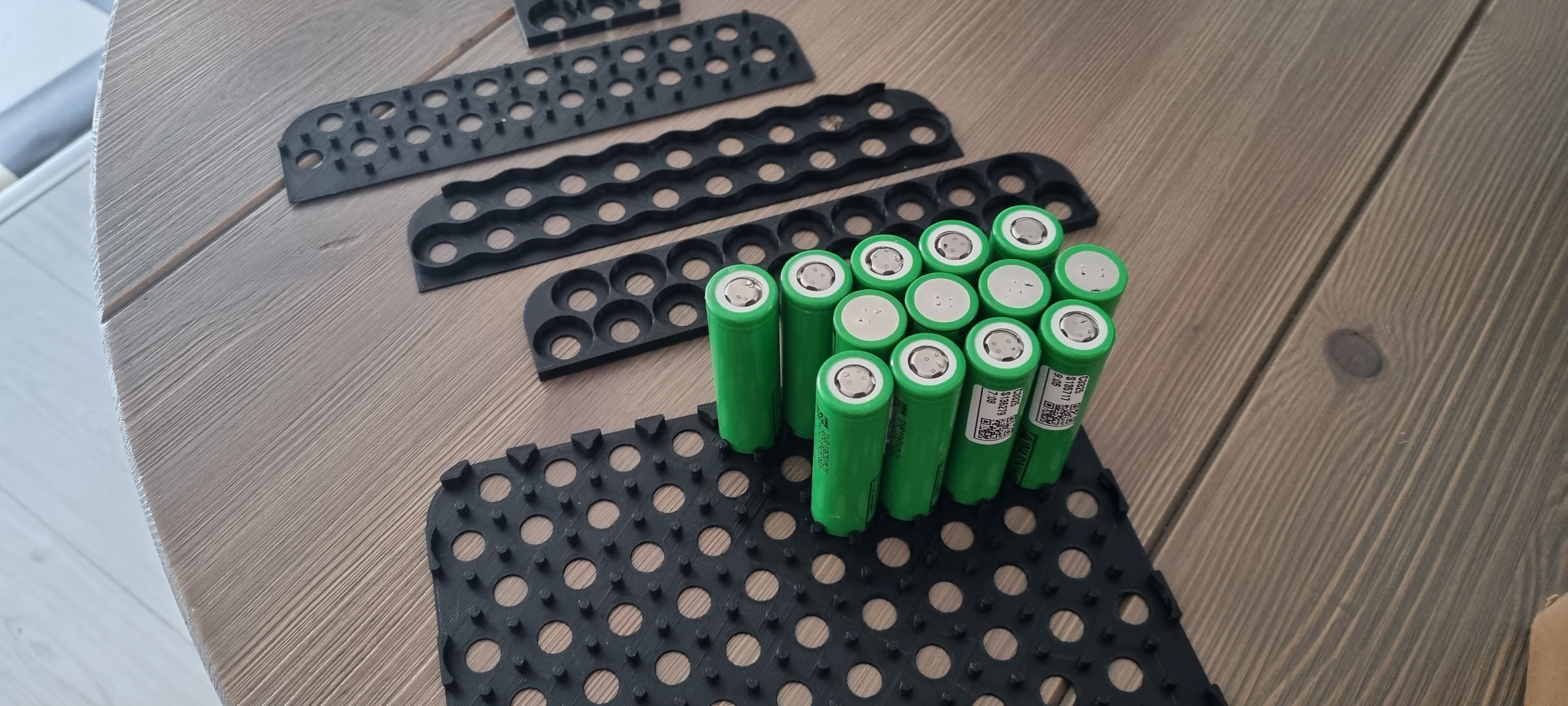
@ Alexandre; well they should fit. Originally I designed with the 18mm of a "18"650 cell and the inside dimensions of the box (square). Should have fitted 196 cells. But…
The cells are in fact 18,3-18,4mm in diameter
There is a label placed on these used cells by the inspection company, which is almost impossible to remove. Thus randomly the cells are 18.5-18.6mm in diameter.
I like the idea of having a small gap between cells to make sure the outside (GND’s) are not touching.
Well I ended up making a spacer for 180 cells, of which I will used 14 * 12 = 168. (13*13 = 169 would also fit).
The remaining space will be used for the inside of grummets/connectors and an additional 200A fuse.
Due to the size of the printer bed, it is made out of two parts. Which should connect with mini dove tails. I tried different holder shapes, but pins with a small angle to them have a nice alligning function and are the strongest (3D printed).
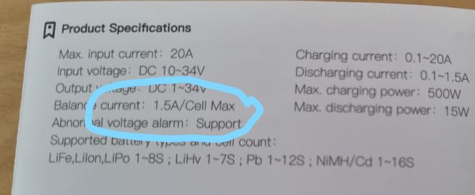
@ Flightjunkie; good point you are making. So I had a look at the IDST Q8 manual, which states the max balance current is 1,5A/cell.
The balance board has a max balance current of 1,2A/cell, which is relatively close to the charger. I see a couple of fat 1Ohm resistors on the board which I asume will indeed burn the difference to balance.
Now I have two options:
Permanently attach the balance board (thus inside the enclosure). It is possible that it will not keep up during discharge, but it will do its job during charging.
Make two “7s12p” batteries and use connectors like you did to balance them externally with the charger. (could also do this with the balance board).
I like option 1, thus only two wires going in and out of the battery box. But I need to test this under load to see how hot the balance board runs and how (un) even the cells turn out to behave.
The balance bord will discharge the highest row to the lowest … all the time , so not the best if something goes wrong …
The new icharger x12 is out : 12s , for 14s still need to split the pack into 2x 7s
But another idea , is to do a 14s pack but to add a charge plug in the middle , so you can charge one 7s side at the time ( even if the rest in weld together ) so only 2 bus bar , 3 charge leads , pack charged in two times
Thanks for the input! I really like all the feedback I receive. I will add the “fatter” charging lead between 7 and 8. So that ability remains.
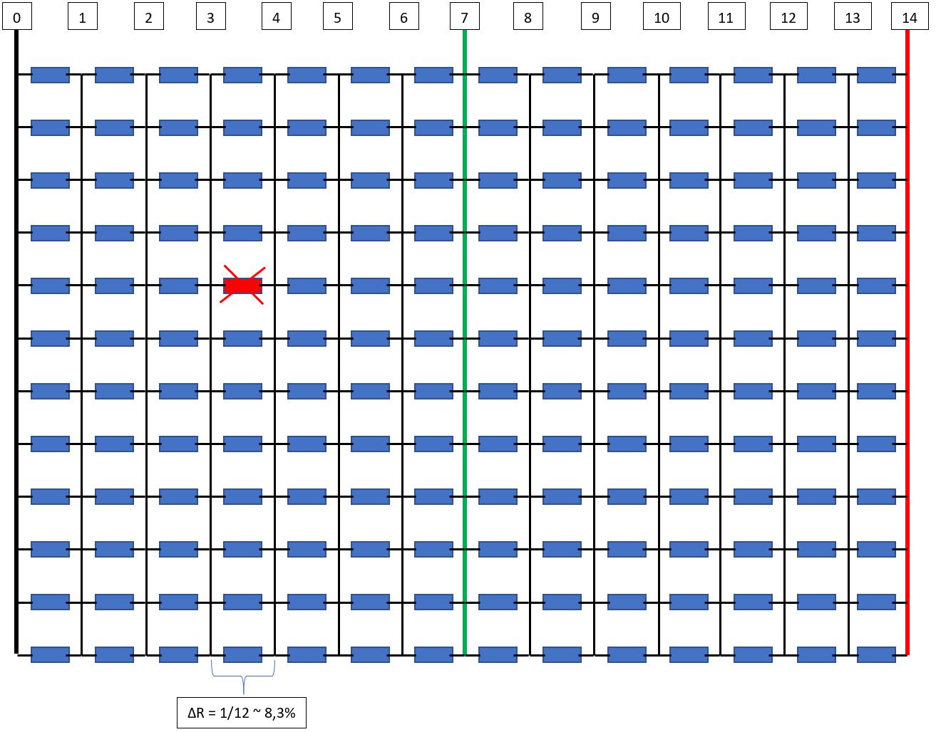
Well for time that something goes wrong I have the individually fused cells. That should help if one cells quit doing its job. My idea is that the if 1 of the 12 parallel grouped cells goes bad, the balance board is still keeping up while charging the complete battery pack in series. Let me try to illustrate below.
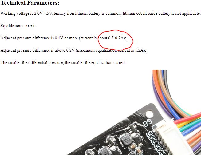
Theoritaclly the resistance of this parallel group now deviates with 8,3% with the rest of the pack. If I charge it with 4A in series. The deviation of one “bad” cell, would result in 4A * 8,3% = 0.332A of balance current. With the ability of the balance board to balance 0,7 A under preferred conditions, gives a Margin of Safety of 2,1. (1,2A gives a MoS of 3.6). This leaves room for individually cell deviations, faster charging etc. But again I have to see if it will work.
Li-ion batteries must be balance charged. Either with a smart charger that monitors each cell voltage, or with a BMS that monitors each cell voltage and can interrupt the charge current.
A balance board with a 2A discharge current is not enough to prevent damage to your battery, and or a dangerous thermal runaway.
There are a lot of reasons why the voltage can spike on any given cell group during charge. The charging system used must be able to stop the charge if a cell group exceeds 4.2 volts.
I have had many times when my charger stopped charging because it detected high voltage on a cell. Any Li-ion balance charger will do this.
Charging your battery the way you describe is extremely dangerous and sooner or later the battery is going to explode or catch fire. And if you haven’t seen what happens when a 2 Kwh battery goes it’s scary. It’ll burn your whole city block down and or destroy your car.
Once the battery has been damaged with cell voltage above 4.2 it’s a ticking time bomb. It might thermally runaway while on charge, or it might later while being stored or used.
Commercial built batteries that charge with a simple charger are protected by a BMS that monitors the individual cell voltage and can interrupt the charge current if a problem is detected. I don’t trust BMSs. So I balance charge.
These batteries demand respect. Please be careful.
Holy… that is some serious fireworks. Message is clear, don’t joke with overvoltage. I think I will solder three balance leads (2x7s to external and 1x14s internal) to the battery pack. Since I can always simply open the case. The external ones are for the undervoltage alarms during riding. But I hope the vesc/maytech remote gives a good enough estimate of battery status.
For charging:
Either split the pack in two with a RC charger.
Try the balance board (and set the upper cut of voltage on 93% if total voltage) Of course carefully watching the cells during the charging.
Whether you use a BMS or balance leads, the routing of balance wires is important - avoid crossing them, and don’t allow them to be rubbed/worn or crushed. Any shorting between balance leads, or to a battery casing, could cause disaster. A balance connector is another place where shorts could occur.
I’m using littelfuse pico 2a fuses on my balance leads, they’re as small as a resistor.
The plastic enclosure I purchased on aliexpress was way too flimsy, so I’m going to build an acrylic case like yours. Have you secured the battery so it can’t move, such as when it’s upside down?
I think I’ll cut some threads in the corners to hold the lid on. I’d prefer a soft gasket type of glue/seal that I can easily remove for maintenance.
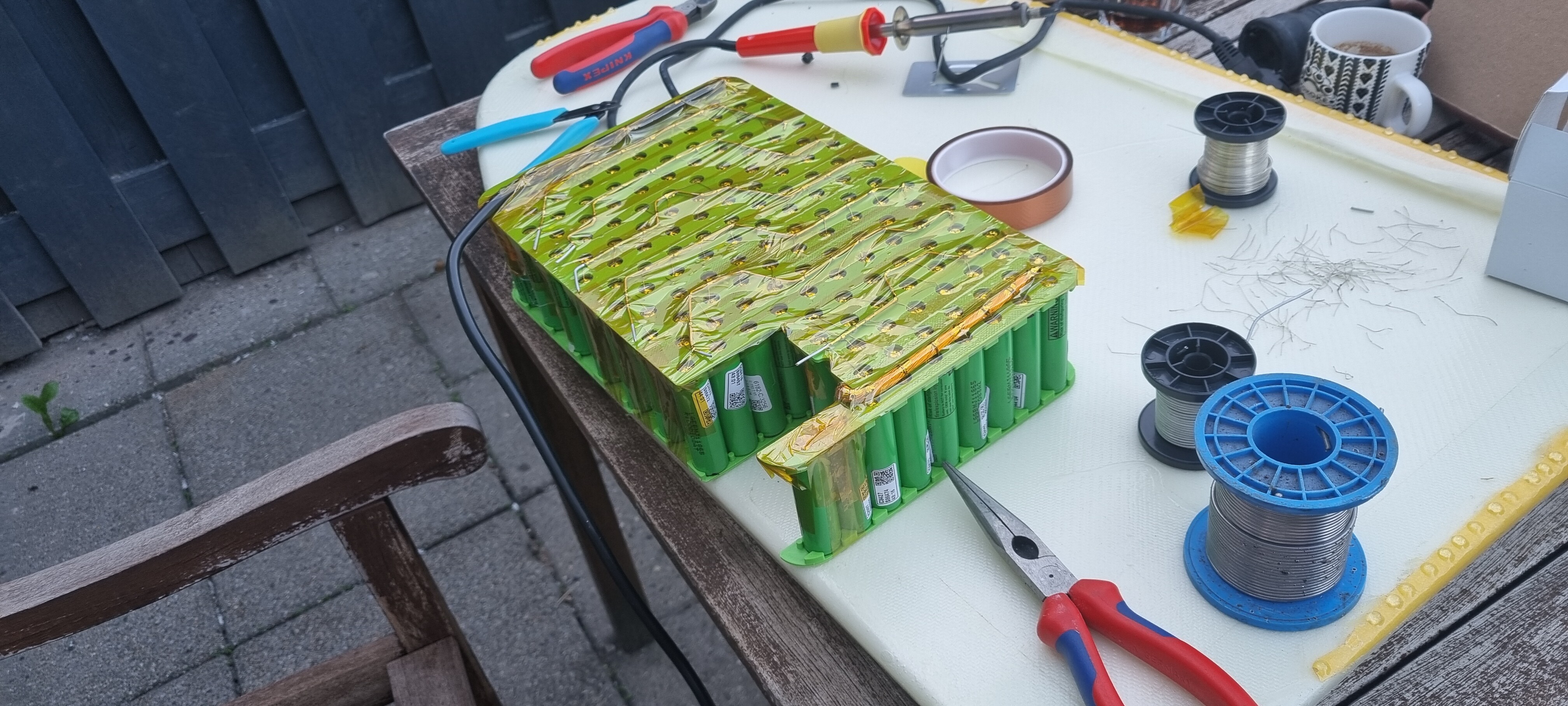
So I have made the battery pack and used the fuse wires directly to put then in series. The parallel groups are done by a thicker copper wire, also used for balancing. The fuse wire is 0,4mm OD, the balance wire is 1,5 OD.
Currently testing the balancer board. The battery holders are replaced with ABS instead of PLA, and PI tape is very nice to properly secure everything, leads wires etc.
I really like your individually fused battery disign! In a reply to someone else you said that it would be better to do a 12s14p in your opinion. Could you elaborate on that?
I also came across this product to individually fuse your cells but I’m not sure it can handle the loads, although in the description they mention they will have one that can handle more amps soon.
The “S” group is what gives you your pack voltage. The “P” group is what gives you the amp hour capacity and the ability to pull higher amp loads on the pack. I went 14s because I wanted a 56v battery pack. 12s will be a 48v battery pack. Less voltage means more amp draw and this requires larger wire size and generates more heat. But, there are many more options for speed controllers at 12s. Not as many can handle 14s. I love the Trampa 75/300 VESC but it’s expensive. So, I guess people prefer 12s because it’s a cheaper build.
Lift and Fliteboard both use 14s14p for a reason. My battery out performed theirs. Same specifications, but I used larger wire size so mine is slightly more efficient.
I hope this answers your question.
As far as the individual cell fusing goes. I didn’t want to spot weld and I wanted to be able to easily change a bad cell. I have only had one cell go bad so far (in a year) and the fuse wire did pop. Battery performed well because this cell was disconnected so it didn’t drag down the rest of the battery. I’m very happy with this design.
VERY helpful! Thank you for your reply! I’ve been leaning towards the 14s14p with the 75/300 but wanted to see if there were any advantages to the 12s14p. Batteries are soo expensive! Thanks again!
Hi Flightjunkie, what an awesome engineered battery pack! Thank you for sharing your journey, tests and very well reasoned and detailed build. I like your determination early on in the thread, and it looks like experience has proven you right! You described the conformal coating on the connectors. Do you use any conformal coating (and yes have to ask corrosion X) inside the waterproof battery housing? E.g. battery terminals, bus bars, fuse wires etc? Are the dessicant bags just for the first build or do you use still use them on all 4 packs you have build? Is the silicone grease and shrinkwrap for the connectors outside of your box? Many thanks
Hi. Thank you for the kind words. I’m glad my build has been of benefit.
Everything is conformal coated. Conformal coating will block an electrical connection. So, be careful not to get it on and contacts or plugs, or things that haven’t been connected together yet. The 18650 batteries, once all connected together, the entire battery is coated it +4 coats of spray on conformal coating. Any moisture in the waterproof box will corrode the batteries, and solder connections, and copper wire. So, I coated everything. I didn’t use any CorrosionX in the battery. But, if the battery ever gets wet you must wash the salt water off, clean it with rubbing alcohol, then soak the whole battery in CorrosionX. Doing this will save the battery if you do it immediately.
The desiccant beads are required, or the humidity in the box will cause it to fog up.
Thanks, that was an excellent answer. I think this thread should have prevented at least 1 or 2 accidents already… For my 3d printer, i am also using dessicant and this hygrometer in my filament drybox, i think it will work well in the transparent battery case. Battery lasts around a year and seems accurate: https://www.amazon.com/Veanic-Electronic-Temperature-Thermometer-Hygrometer/dp/B07GNMKYCZ
Just to confirm my understanding: no conformal coating on connectors mating surface. Douse connectors in corrosion X, heat shrink, conformal coating on non mating surface and silicone grease on connectors outside of the box! Many thanks