I printed DEEP TUTTLE adapter. My custom carbon board has an odd shape, 75mm deep cavity, about 15mm wide. The adapter I printed needs to have 1-2 degree draft angle applied.
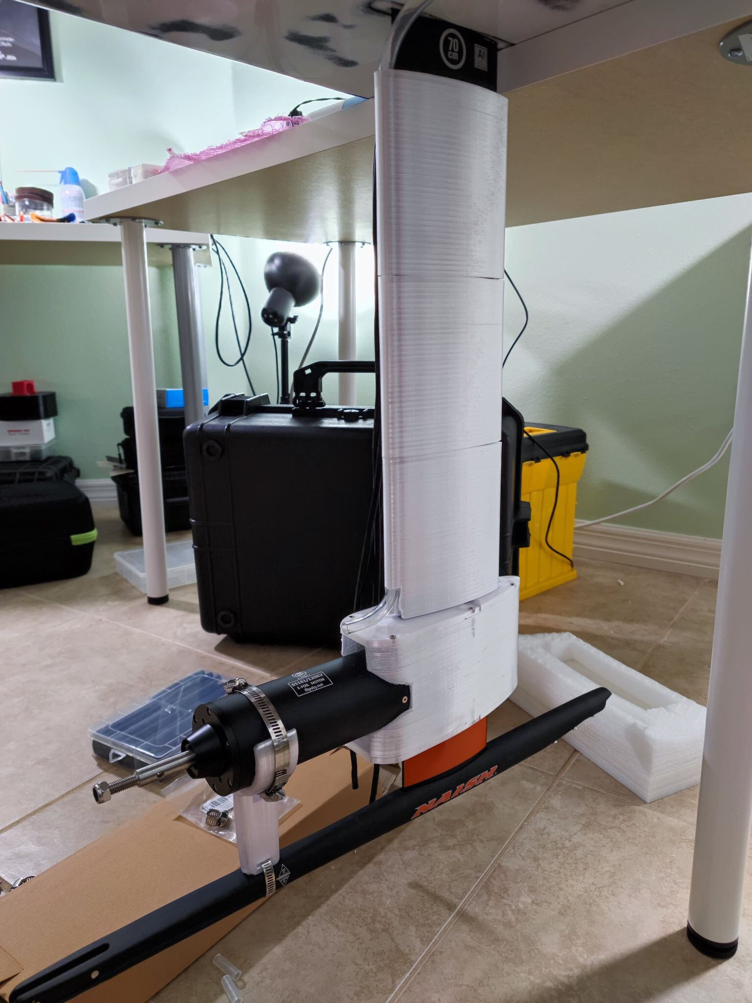
For now I will continue, routing wire and water tube OUTSIDE the mast. If it does not work well, I can easily drill holes and route inside the mast. For now, I will click “print” and have parts with raceway built in.
Printer is still printing. I have managed to mount the mast to the board. I am working on the electrical box.
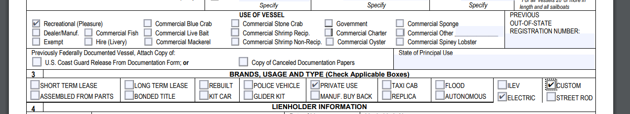
I have ordered an hour-meter so I can register this watercraft in the state of Florida and receive a title, and hull numbers. I am filling out form 87002 and form 82040. I will also need a horn I think, and a whistle on my PFD.
I have ordered M4 Well Nut (Neoprene and EPDM variety, to compare) to secure Battery Box to the board using holes which already exist. There are pairs of 3 holes, so I will use the middle hole to secure box, and 2 outside holes for hand strap or handle.
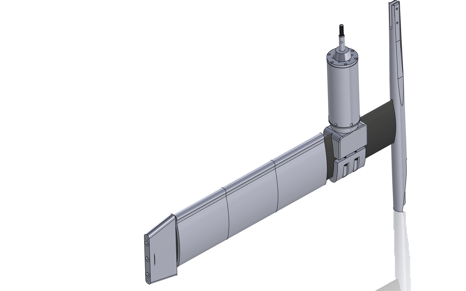
For transport I can unfasten the tube clamp, separate fuse from mast, and the mast is hot-swap from the deep tuttle box. I am using both conductors on XT90 for each motor phase(3 total XT90) to enable hot-swap cable system for the mast.
For transport I will end up with
A) Fuse with wings
B) Mast with motor
C) Board with battery box
I will use a coupler to hot-swap the water cooling line. I used large internal diameter hose, i think this is 3/8 inches.
I think you will be surprised, I will try to datalog on foil and compare to a similar setup which runs cables inside the mast. Lucky I can buy as many batteries as I need, and charge them in under 2 hours.
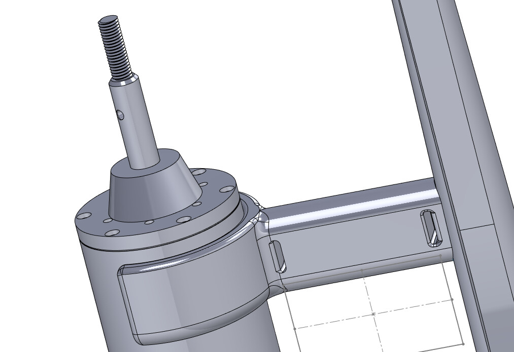
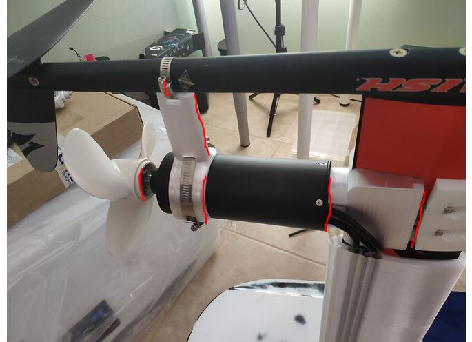
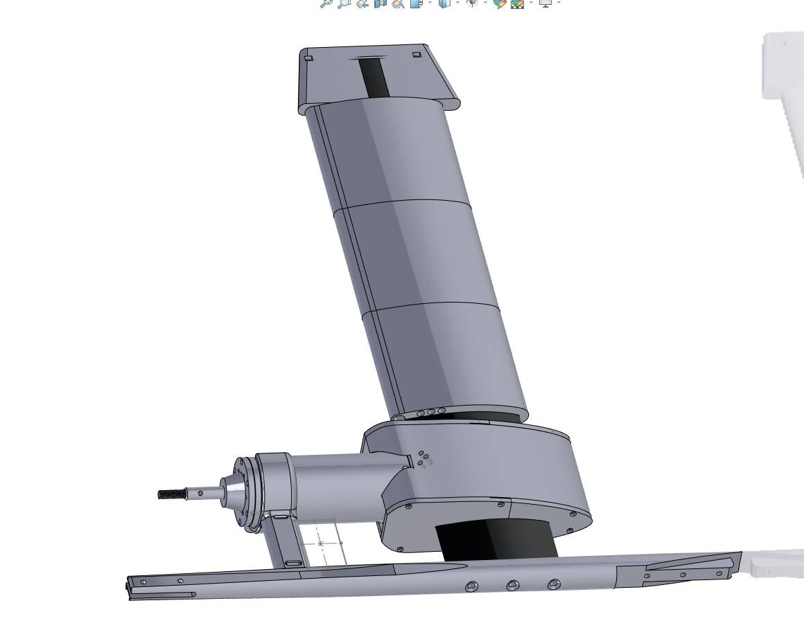
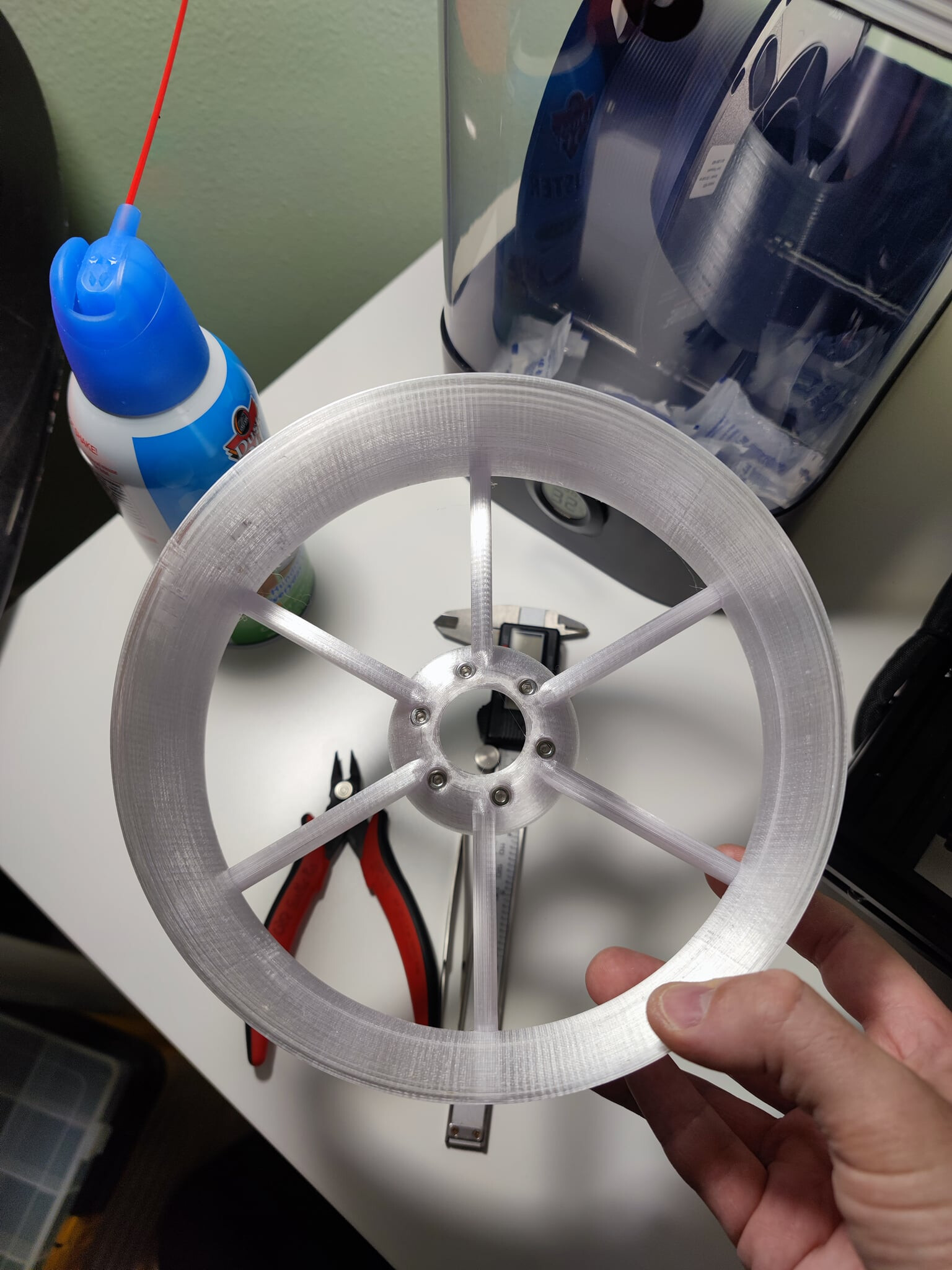
Drag is your enemy for range and amps… Your underwater design could be improved by removing (or streamlining) the hard edges along the moving axis. See the areas in red. Think about printing a streamlined sleeve around the mastclamp in front of the motor, this can be a hollow, 2 piece design.
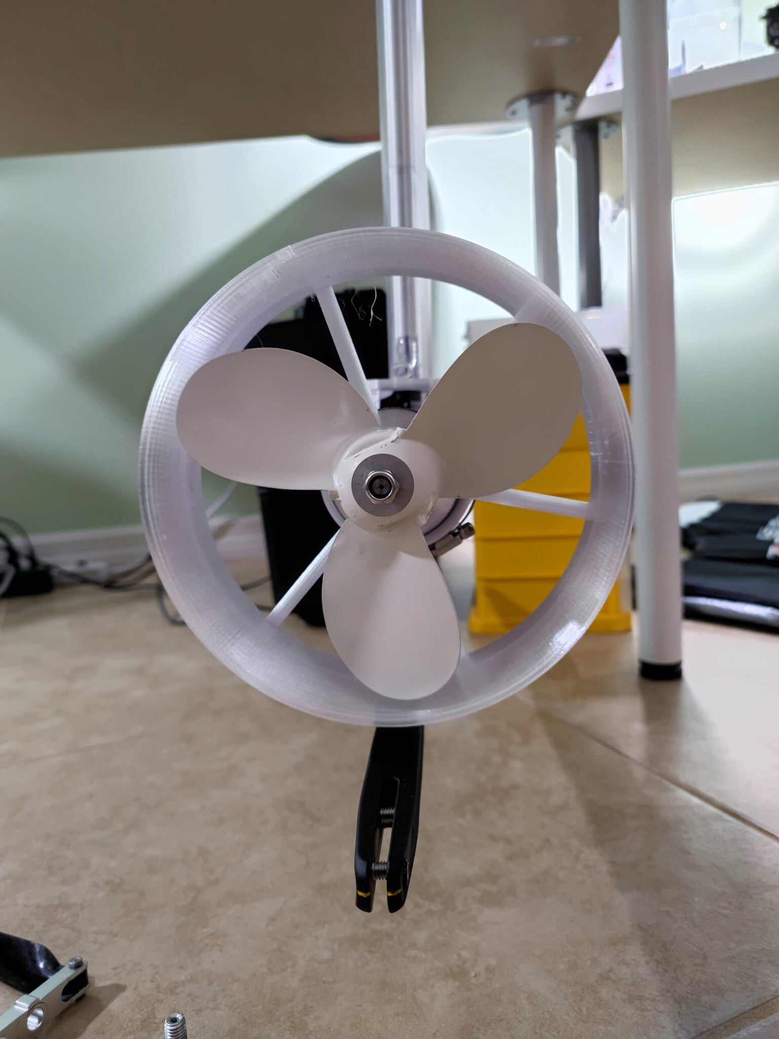
The extra brace support should not be necessary with the aluminium mastclamp and a balanced prop.
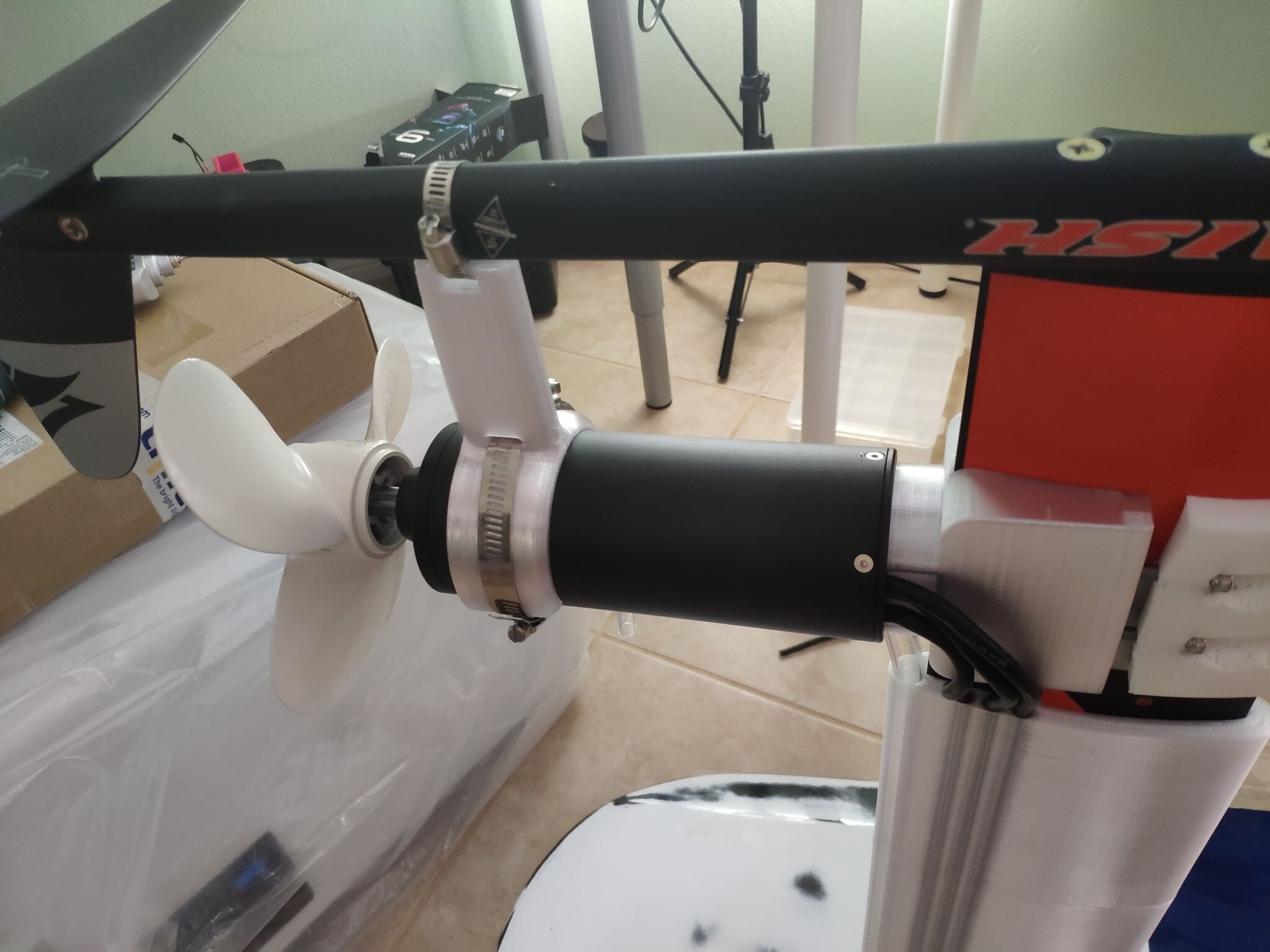
The ‘wire-cover’ around the mast adds some thickness but is mostly above water when flying. But I would cover/guide the wires directly out of the motor.
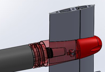
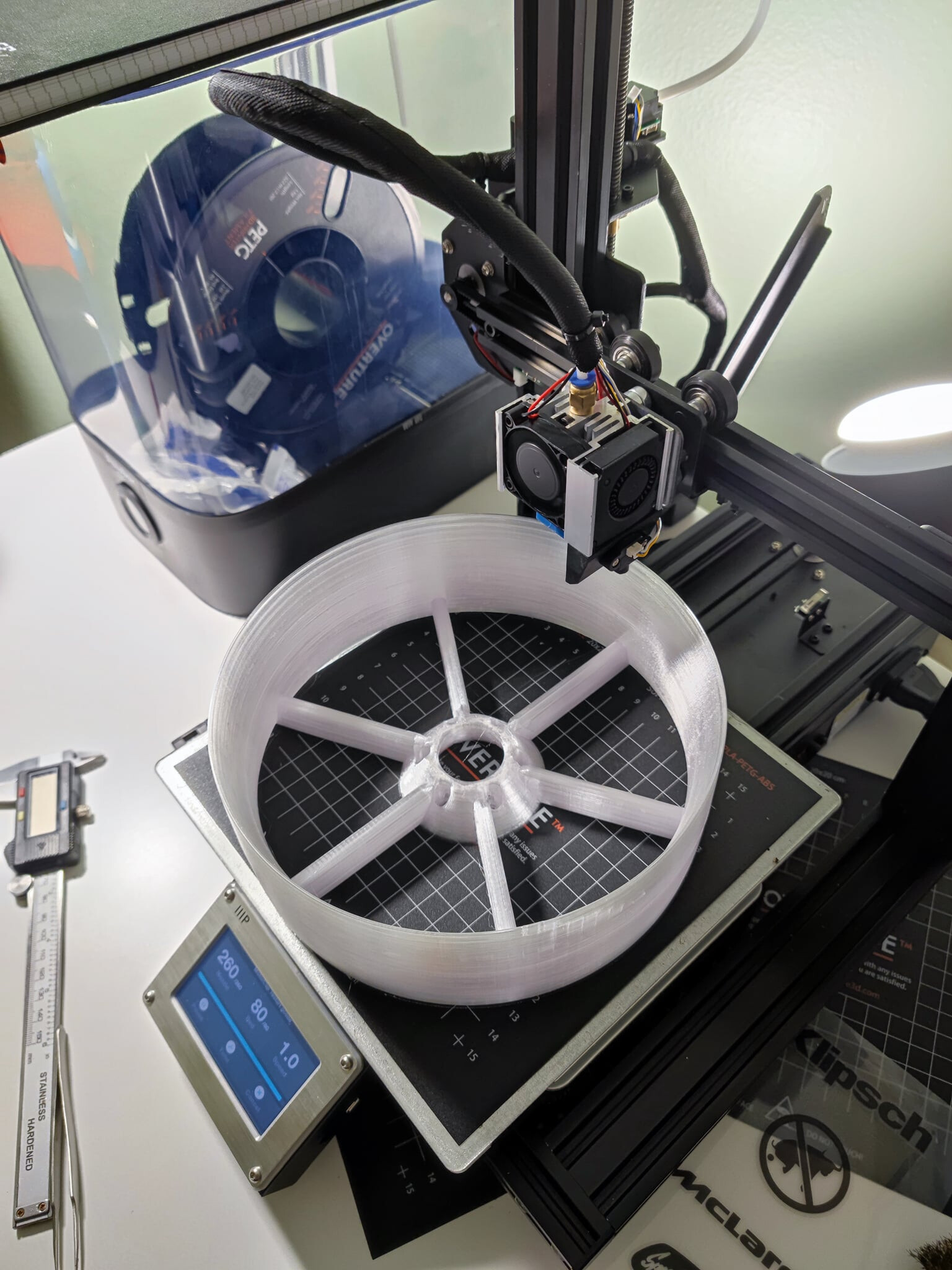
I put the portion we’re concerned with in Flow Simulation to calculate the actual drag coefficient. I have some idle days ahead waiting for the M4 Well Nut to arrive, will keep the printer busy making a shell. It is easy to do, so I will add a streamlined cover for the wire section - but it most likely won’t be conical/dome shaped.
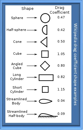
So far with 25 iterations the drag coefficient is converging under 0.50, the cut plot will show more detail. I will run the same simulation after adding the streamlined baffles which cover the wires.
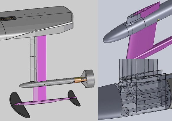
Here is a typical conical shaped build I see on the forums:
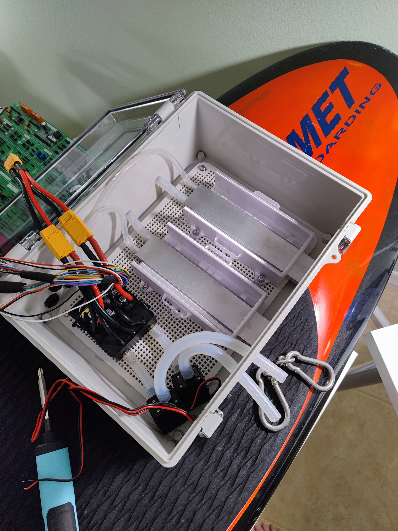
Nice… but never tried and never seen it this way : two pumps mounts and intake in the flow , just make sure , pumps flows don’t take from it others , water intake with stream will take over pump flow
Cooling battery , why not , lipo ? , just on on side , no idea about efficiency , I guess just need to measure IR with vs without cooling on each cells …
Why battery before vesc ? Battery will heat , normal , we don’t heat on the vesc for sure
Hi, VESC is first, battery is second. The battery lies on its side because each of the 6 cells will touch the waterblock. Otherwise I would just be cooling one cell. The battery is manufactured with an aluminum case around the cells, which is touching the aluminum waterblock.
Not sure about inlet/outlet on pump, directions not included and the pump doesn’t have flow indicator. Might need to swap in/out
Edit: I changed in/out, tested the pump using 9v to confirm
Working, no prime bulb. VESC telemetry ok. Throttle working. After all the considerations for water cooling I am tempted to try it without switching on the pumps, see how hot things get for reference.