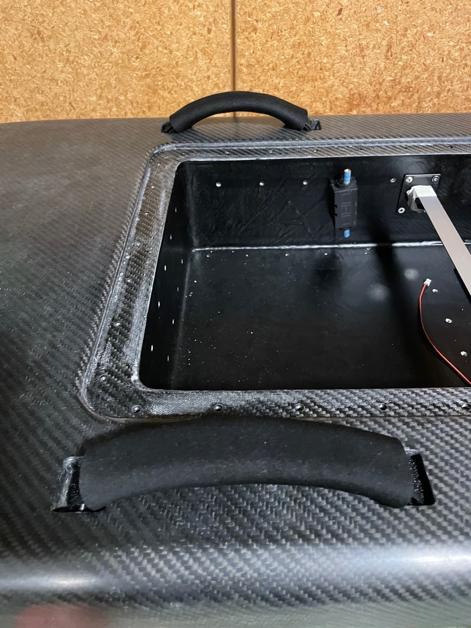
Installed handles, they consist of hoock and loop bands sewed together and a neoprene cover.


5 Likes
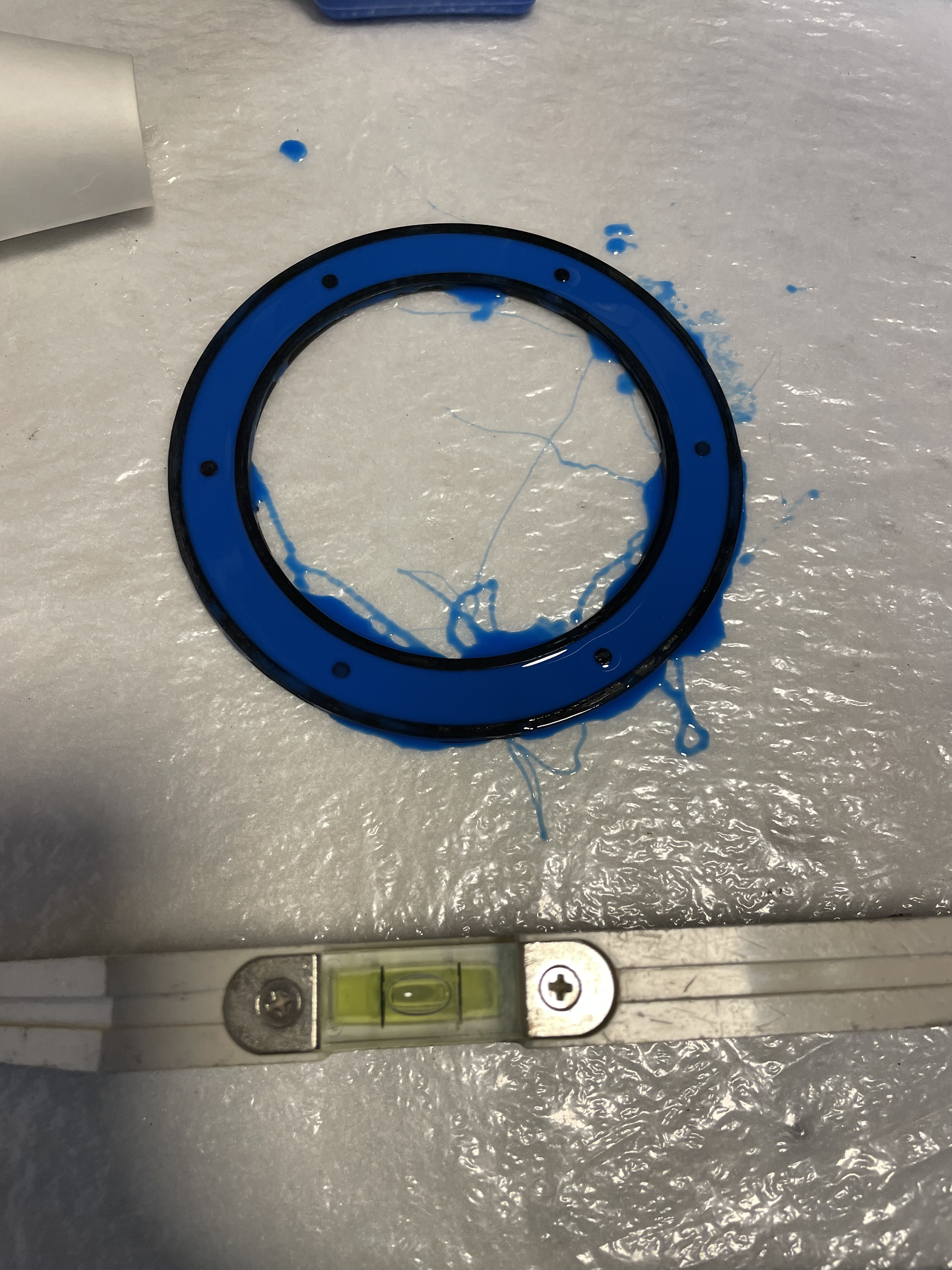
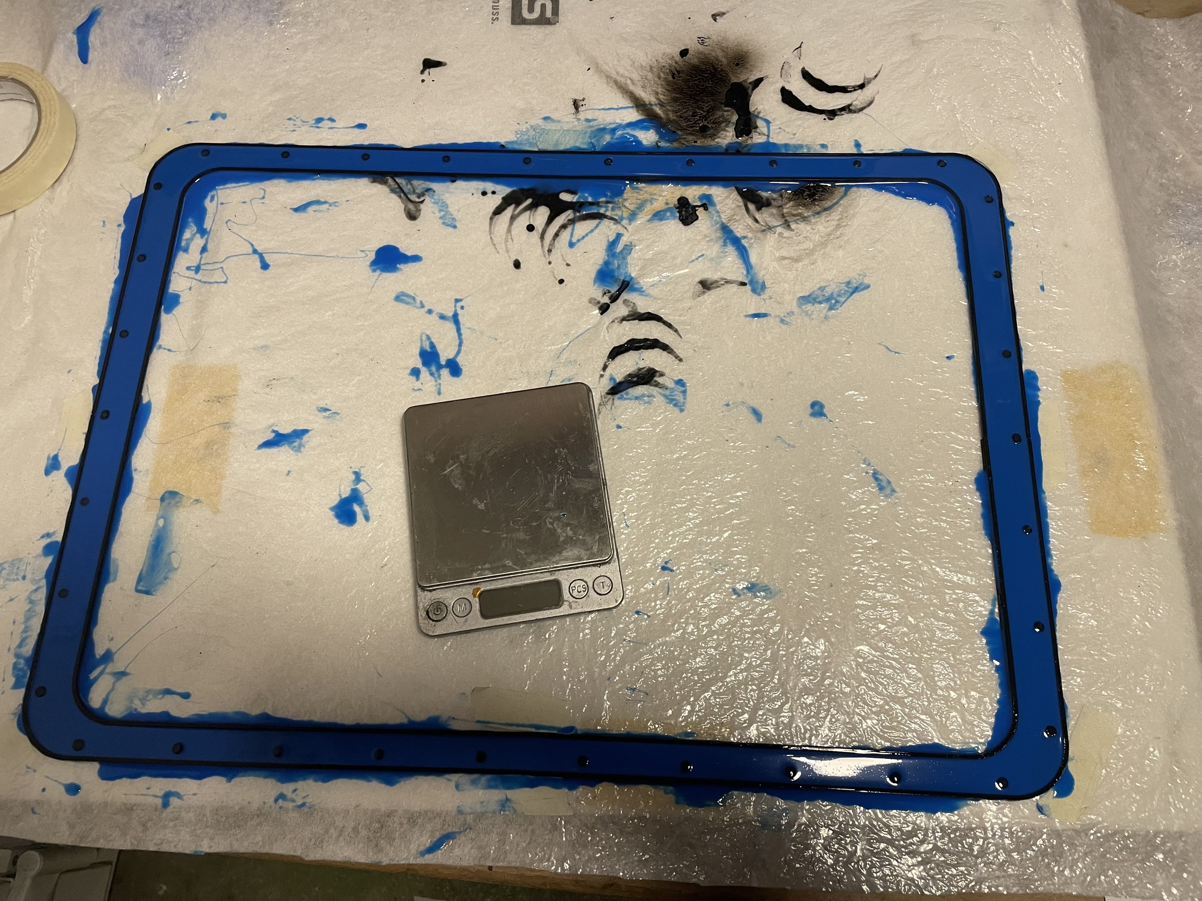
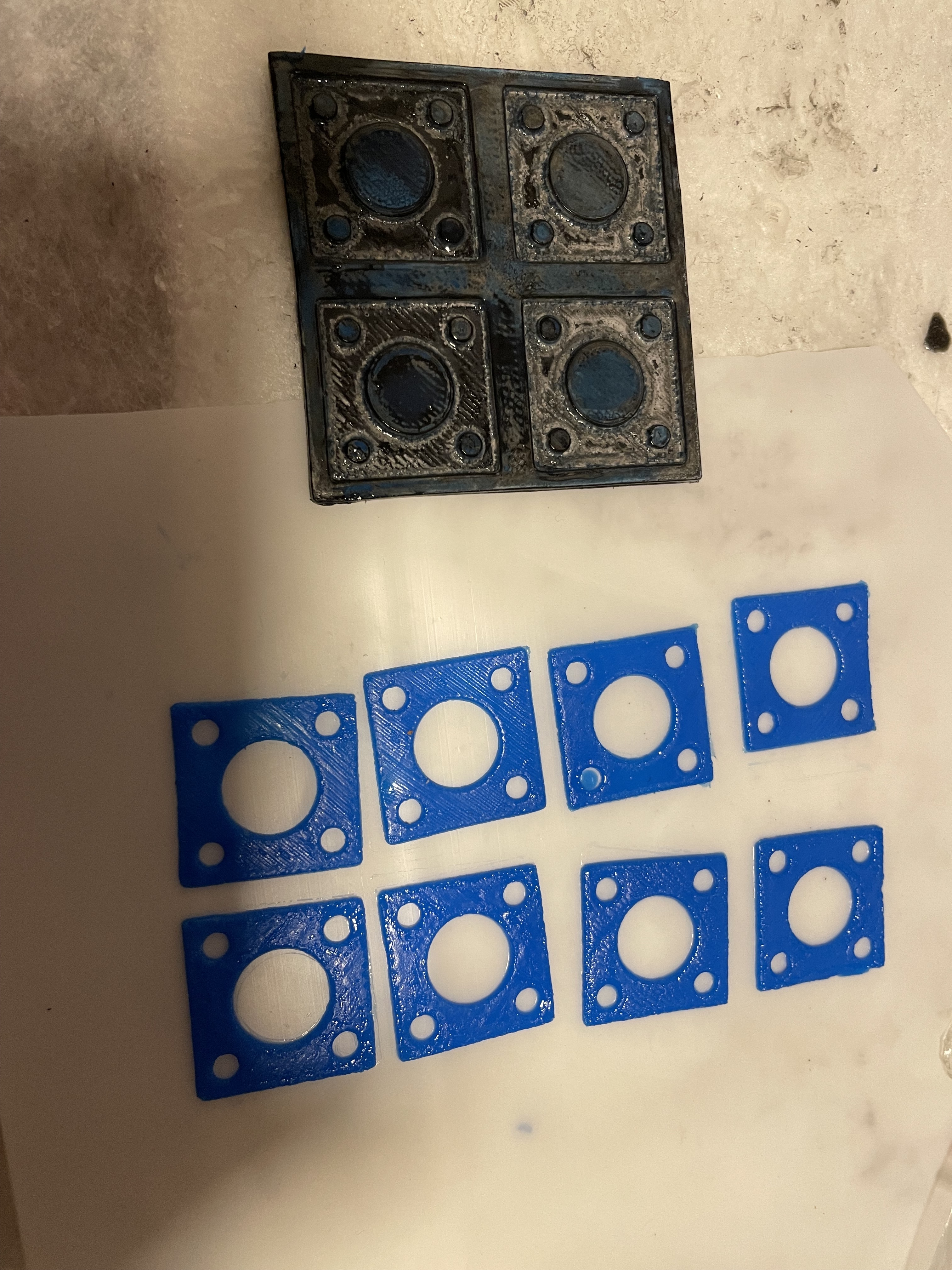
Seals
In my first build I used a self adhesive EPDM seal. It works well but it is not reusable. As it compresses and stays compressed, it needs to be replaced each time the box is opened. It is also annoying to remove the remainig adhesive with acetone.
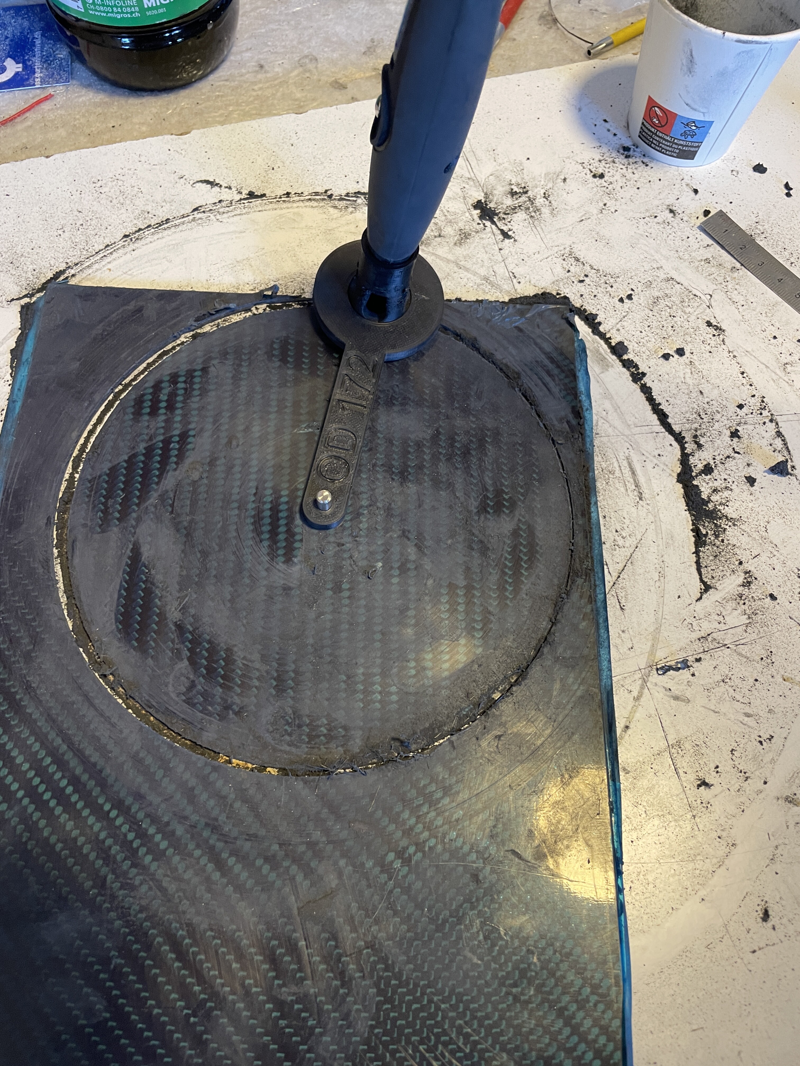
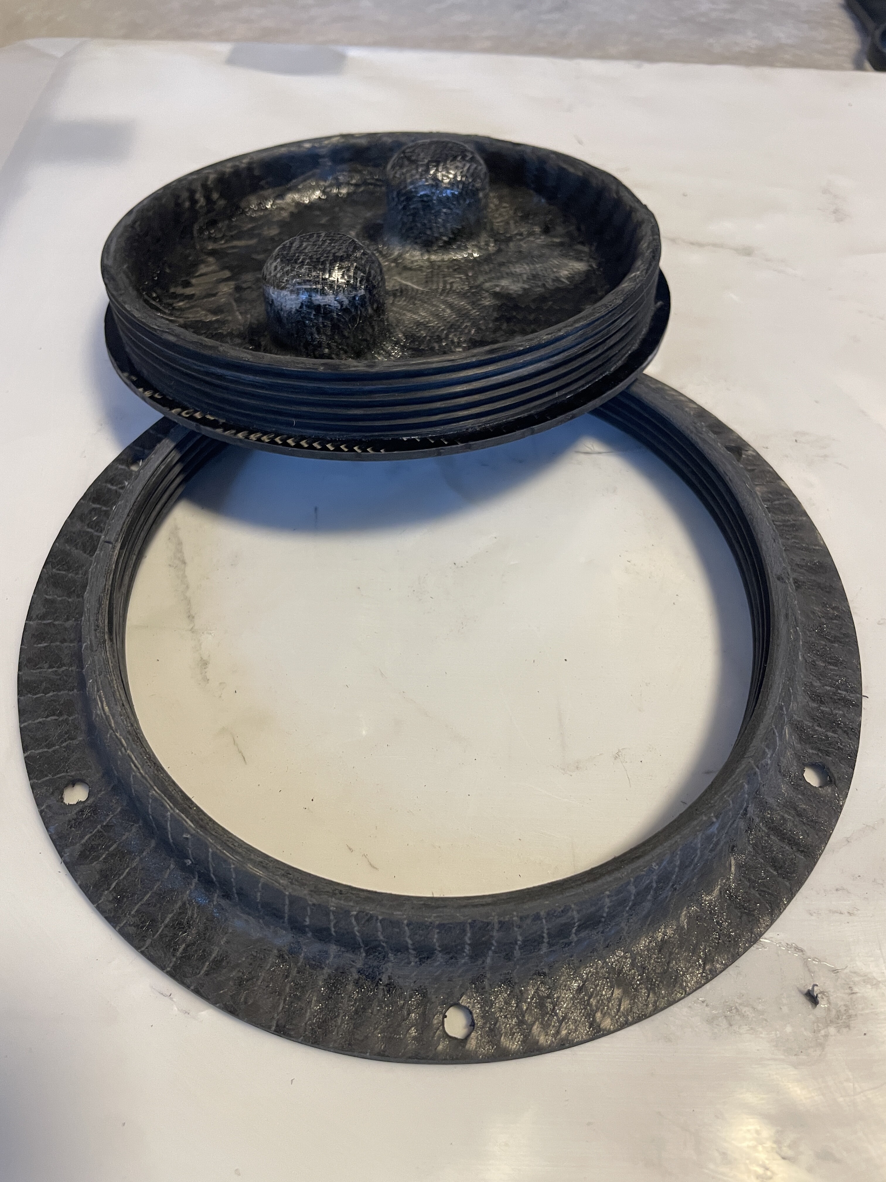
As my new board has many seals, they need to be reusable/easily replaceable. Therefore I made them from Wagnersil 32N 2k silicone. The moulds were 3D printed.
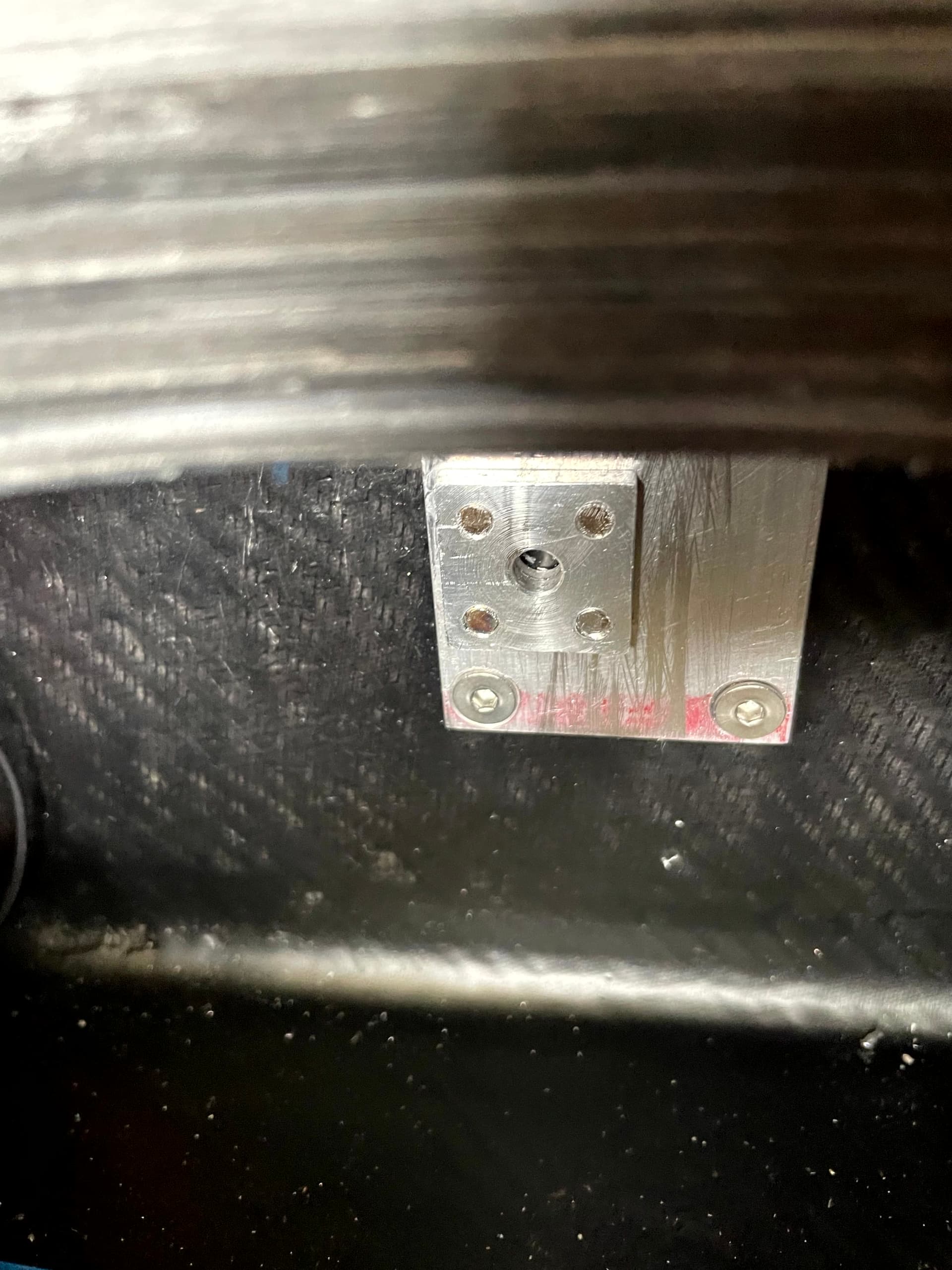
Heat sink:
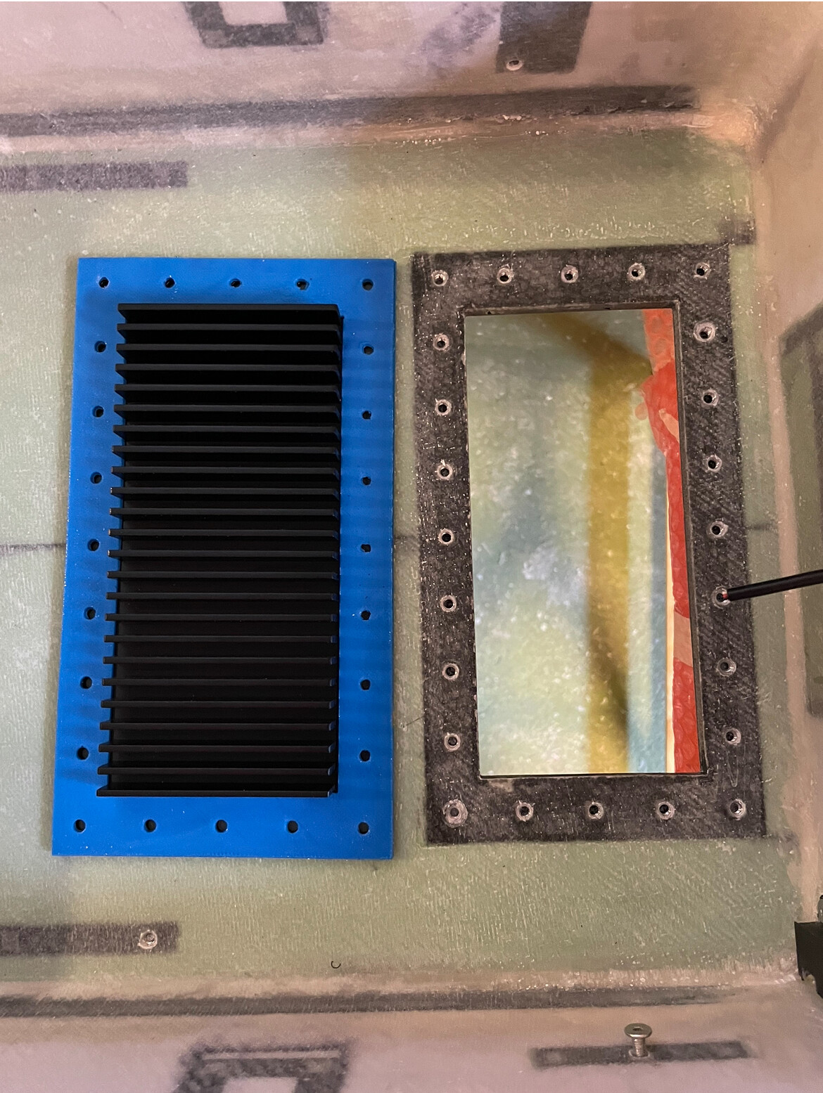
To prevent leakage from underneath the board, I chose a low spacing between the screws that hold the heat sink.
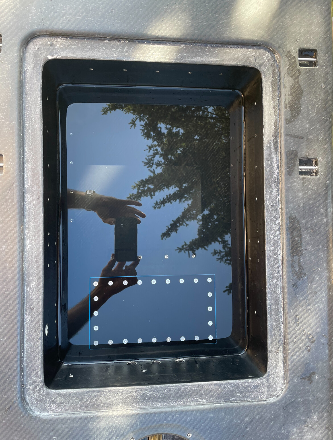
Waterproofness test
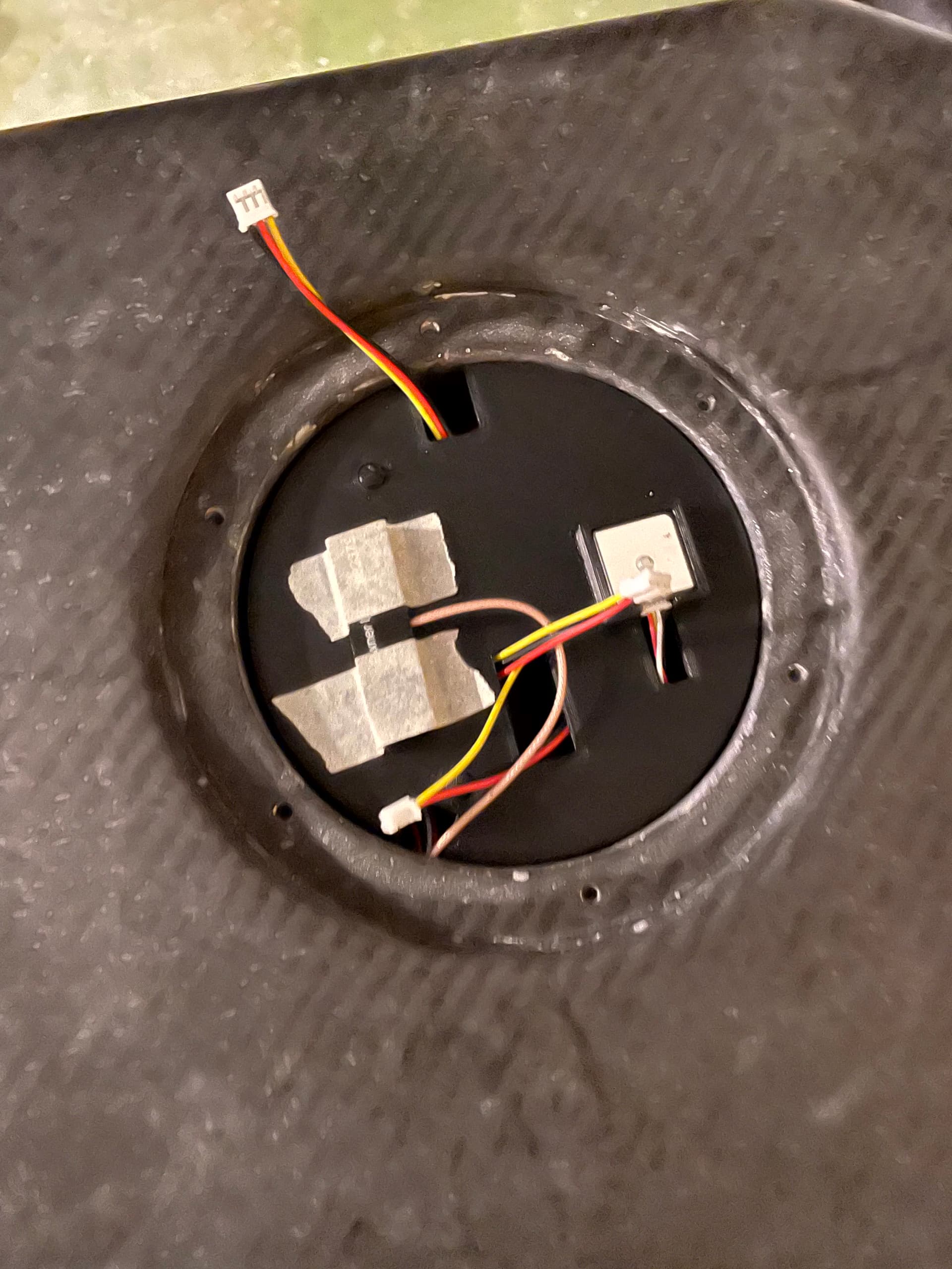
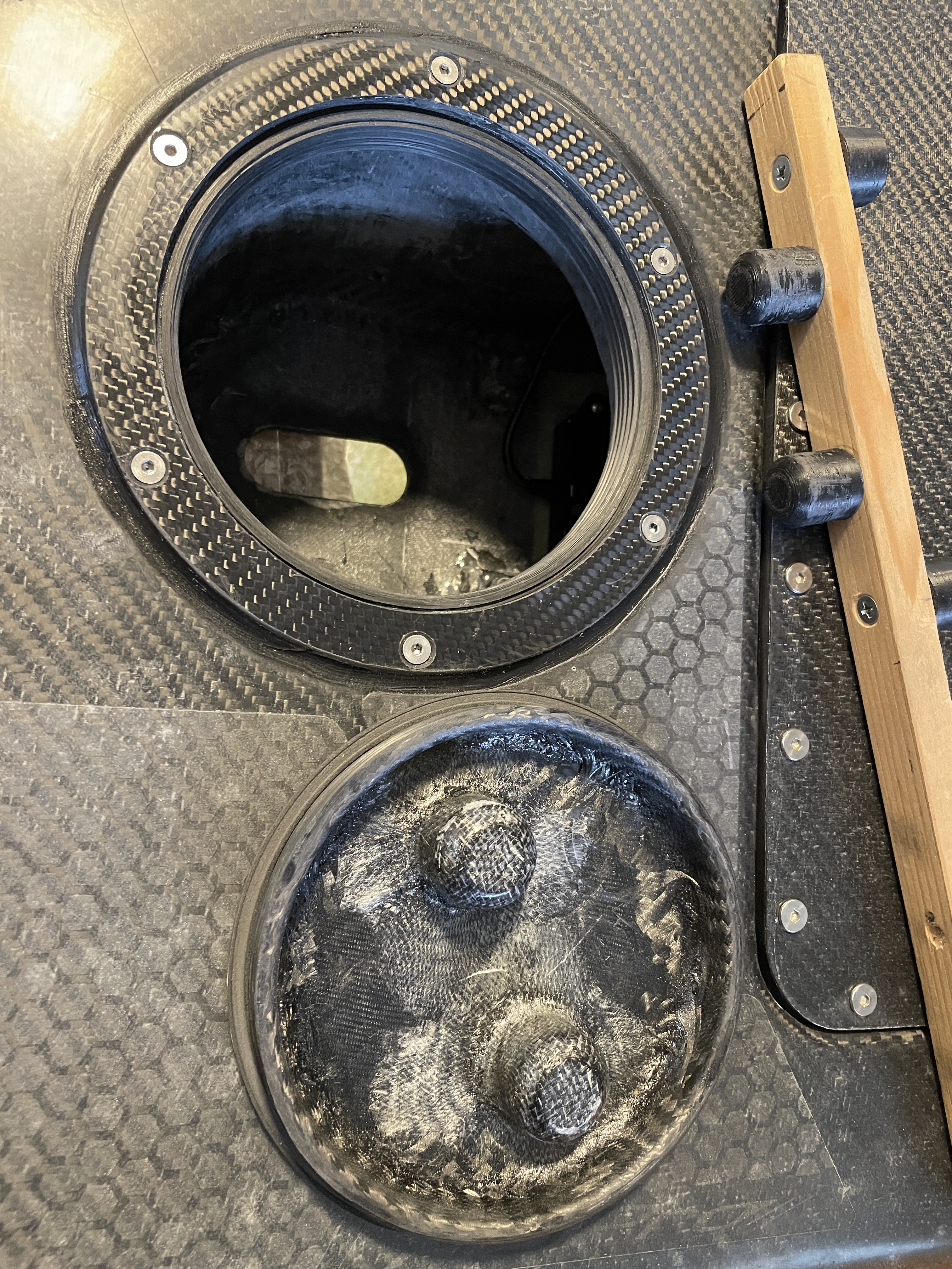
Receiver compartment
Main compartment
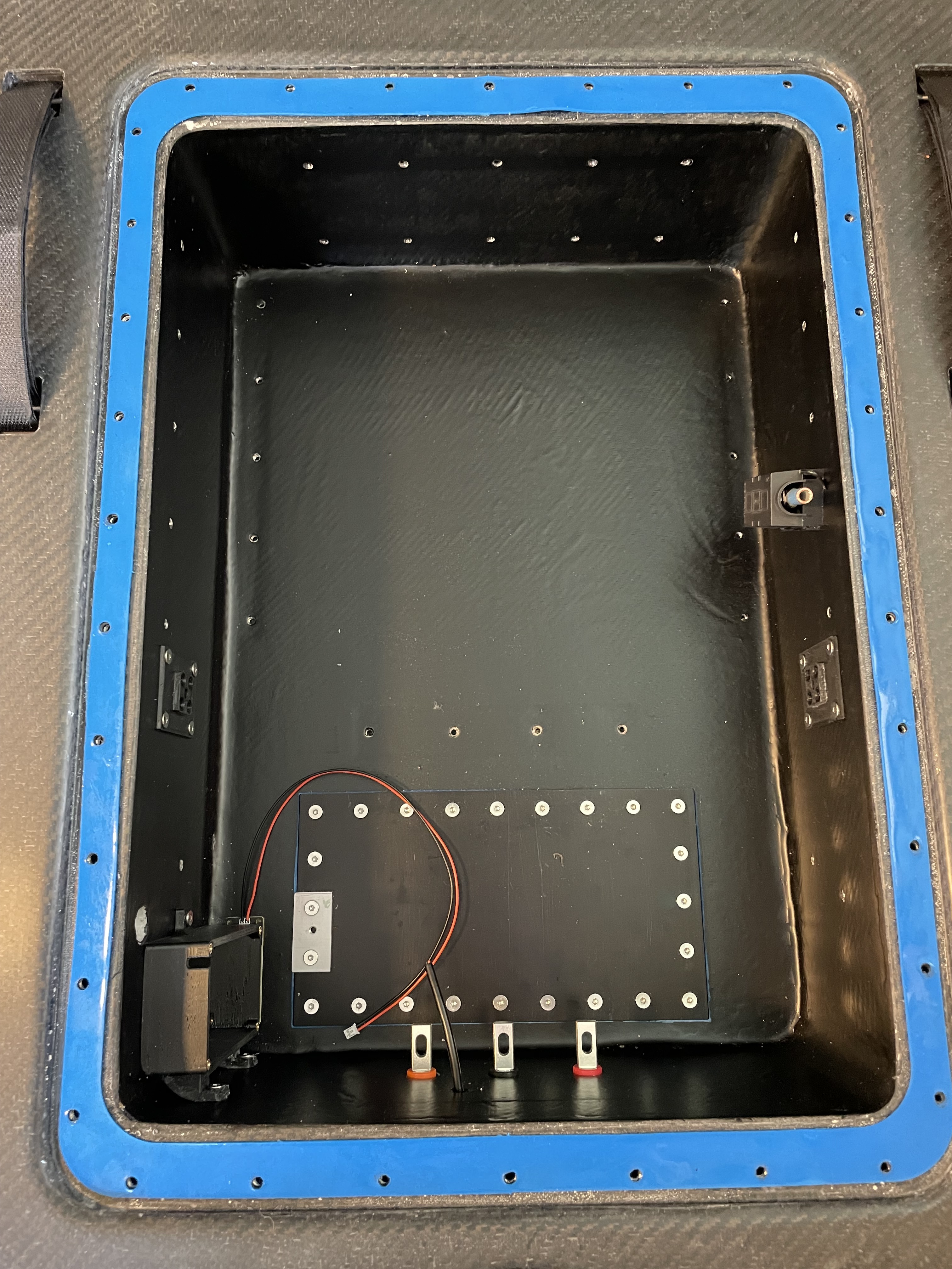
Motor cable compartment
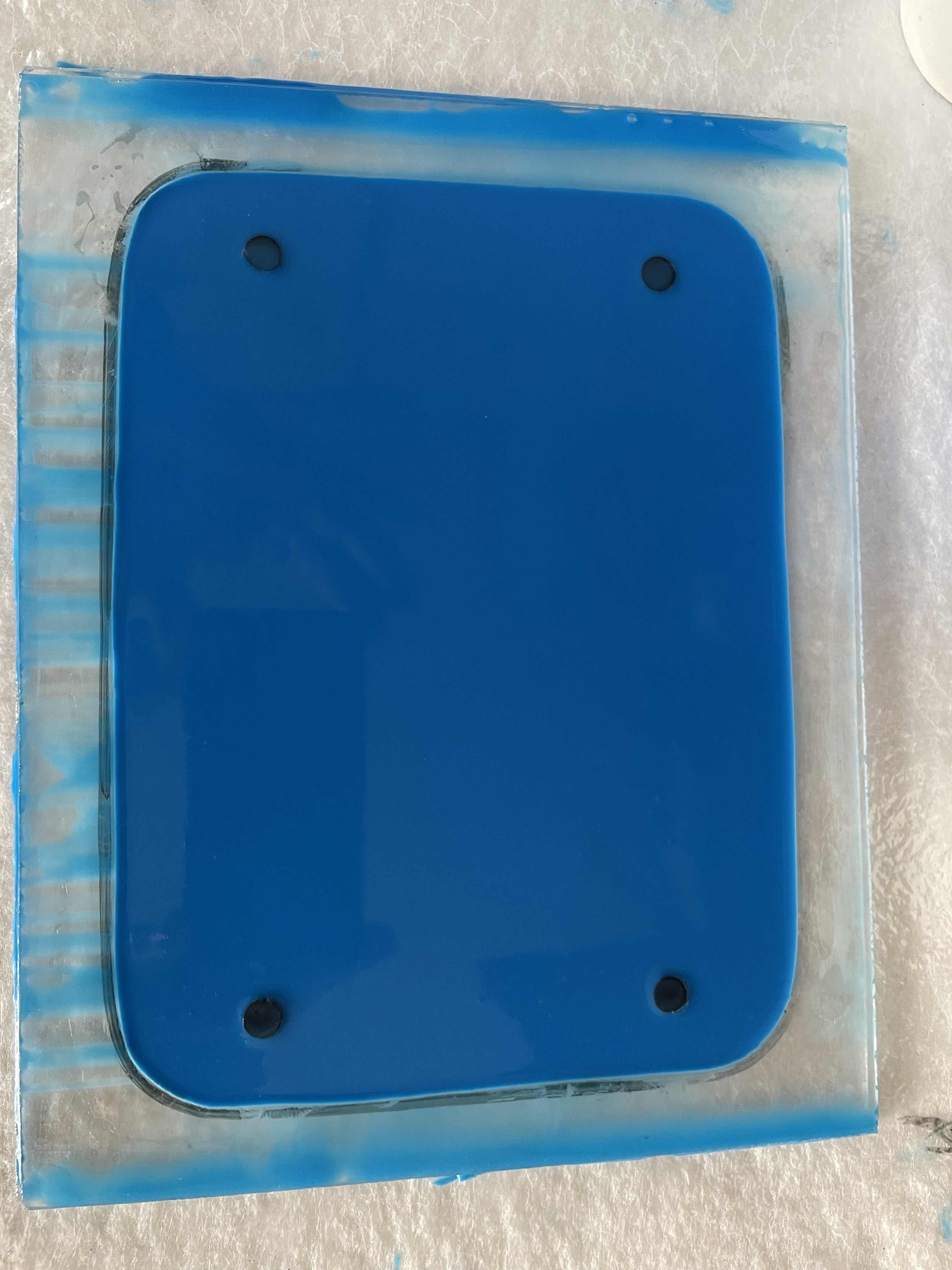
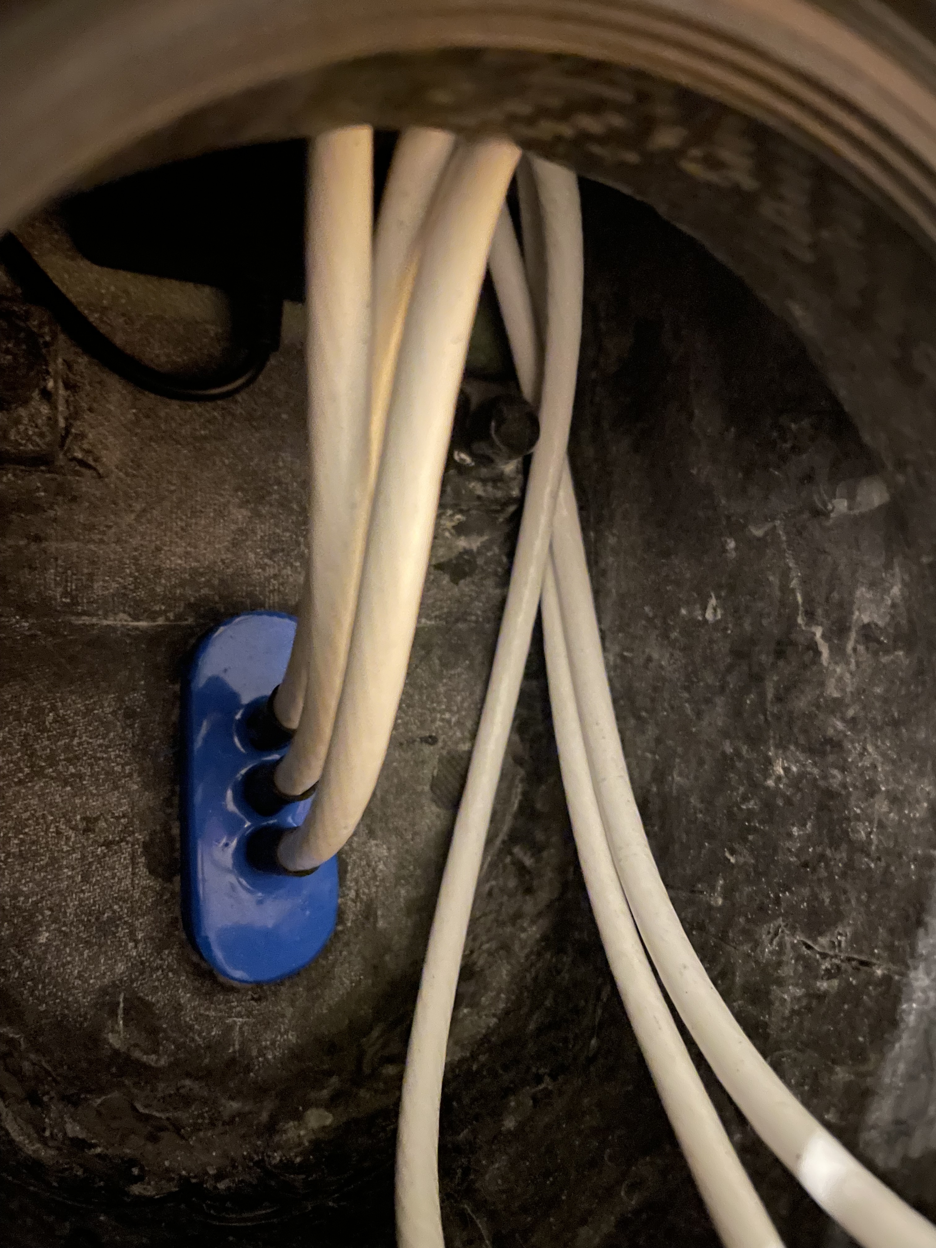
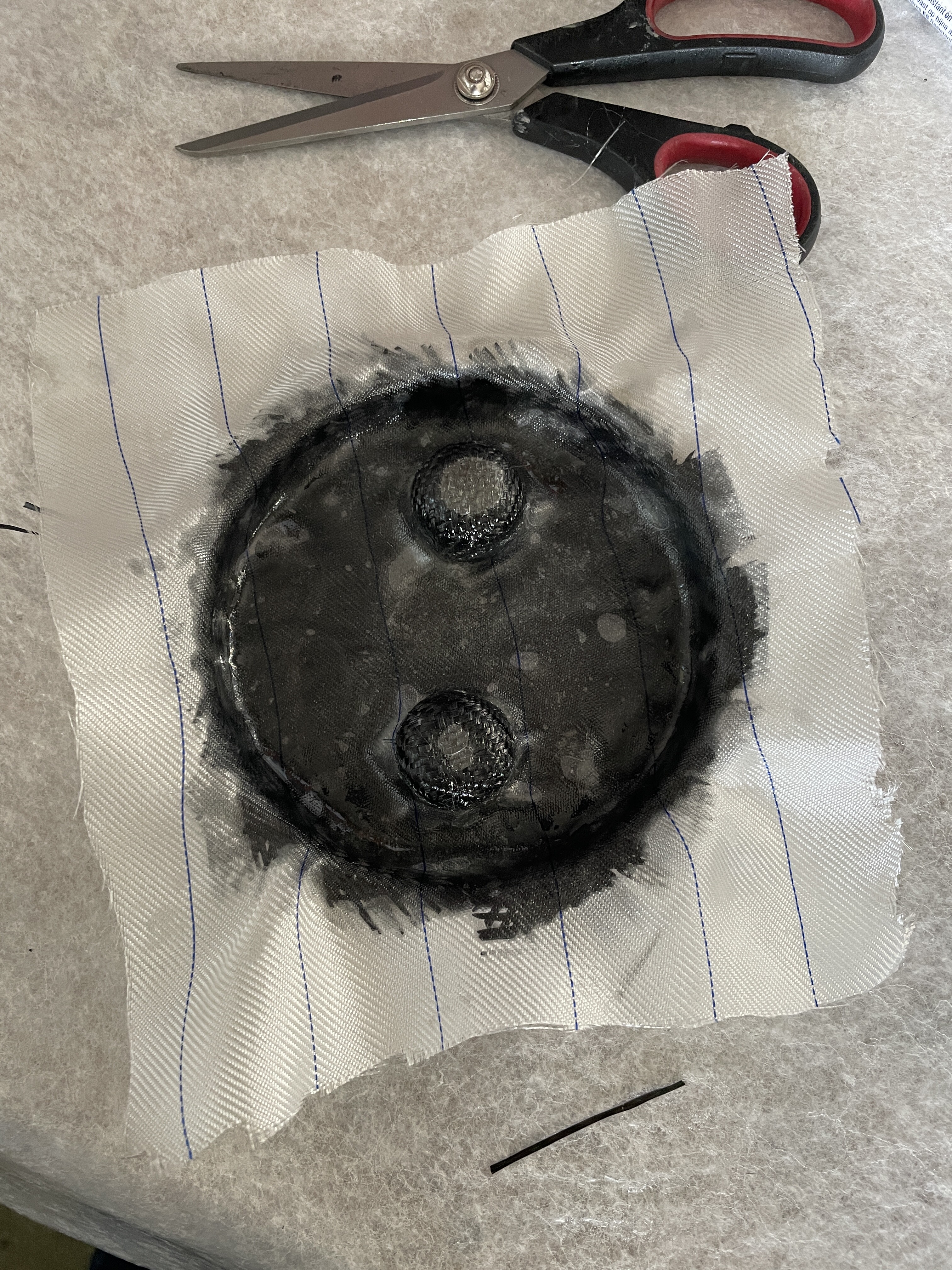
I made this seal in two parts. First I made a flat 2mm thick seal on anacrylic glass plate with a frame cut from 2mm acrylic. Glued 4 3d printed space holders for the screw holes on that mold plate. This way you get a smoother surface than entirely 3d printed.
2nd step was to cut out the center opening for the cables. I cut it bigger than the opening in the board, installedthe seal, added a 3d printed mould part from the inside and poured silicone from the inside.
To my surprise the added silicone sticks to the premade part.
Connectors
Seals were not available when I ordered the Amphenol connectors, therefore I had to build them too.
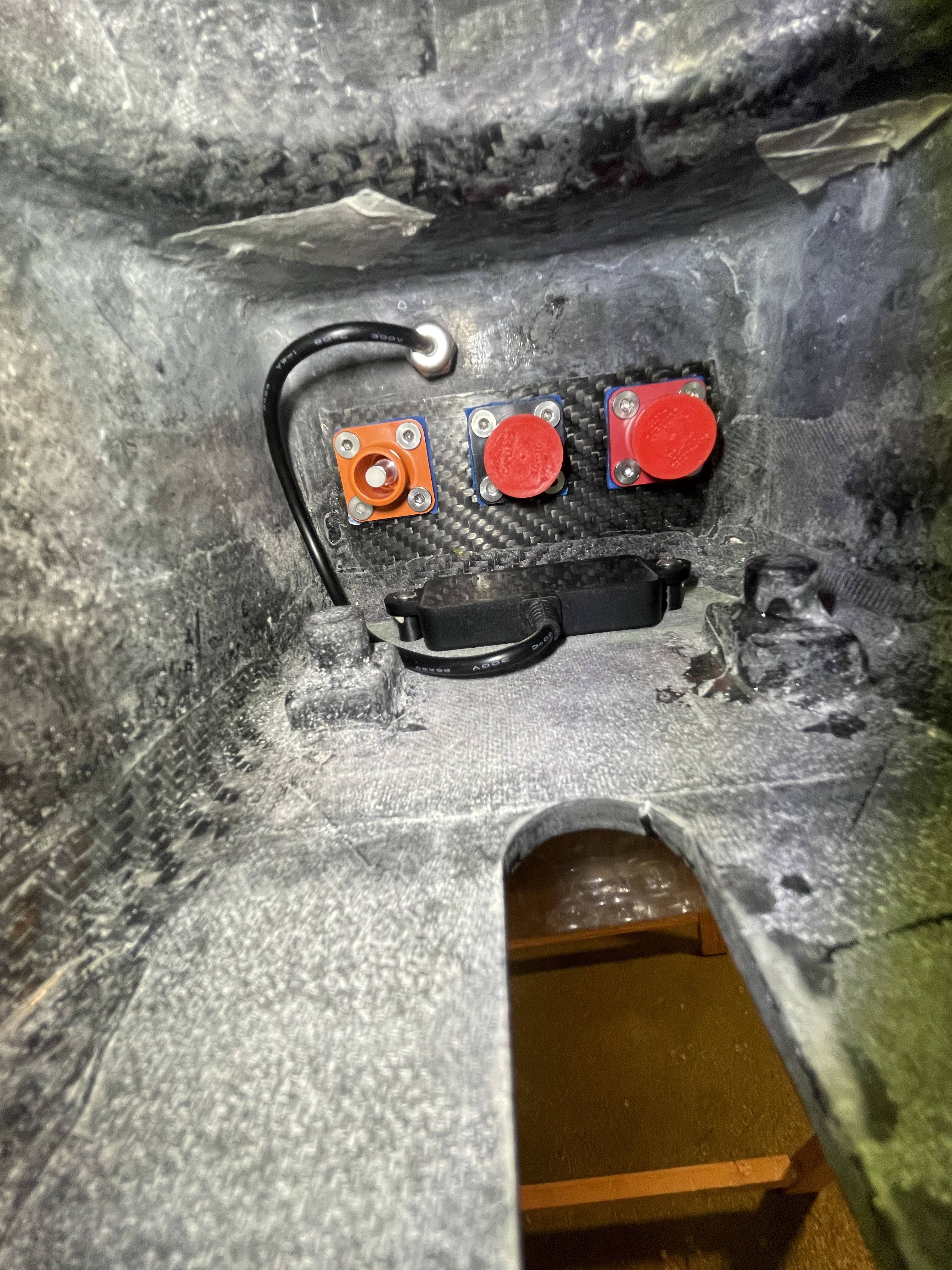
Water Test
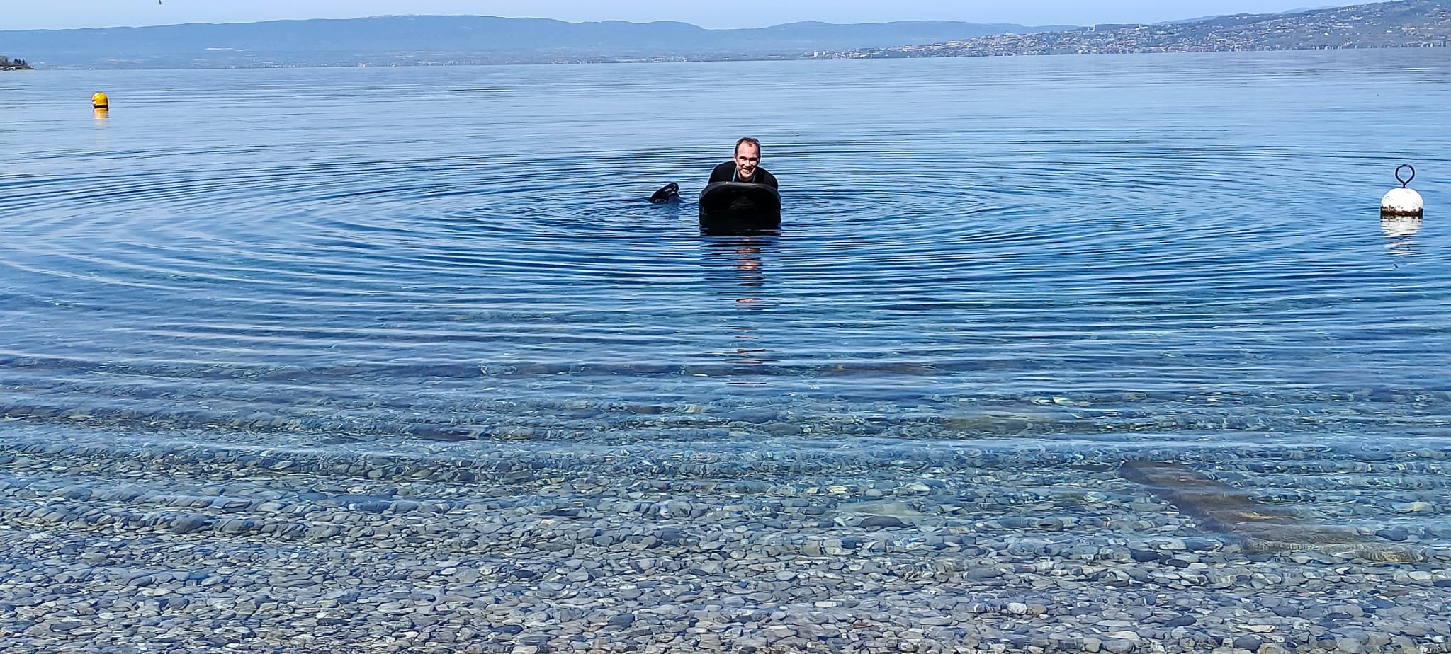
Took it to the lake and put it under water.
Main compartment and receiver compartment are 100% waterproof but here was some leakage in the motor cabling compartment at the back. Not a desaster as the connectors and ultrasonic sensor that sits in there are waterproof. Need to troubleshoot, I guess either the round screw hatch or (more likely) the seals around the ultrasonic sensor leak.
5 Likes
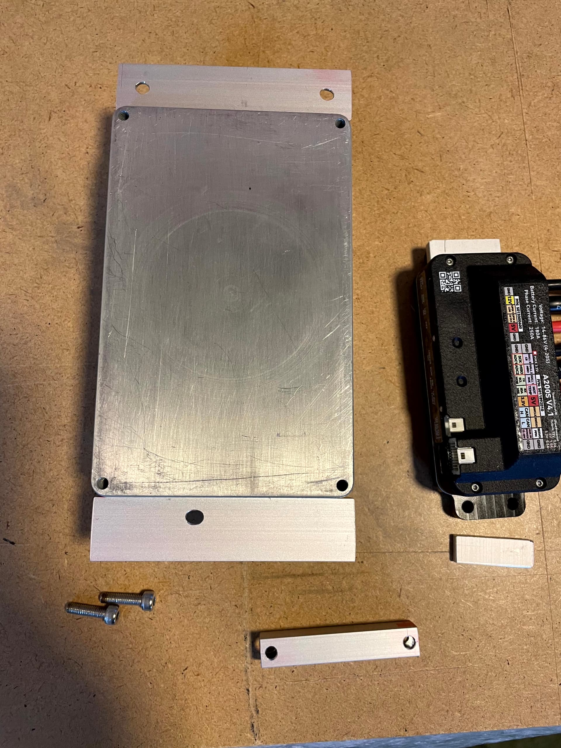
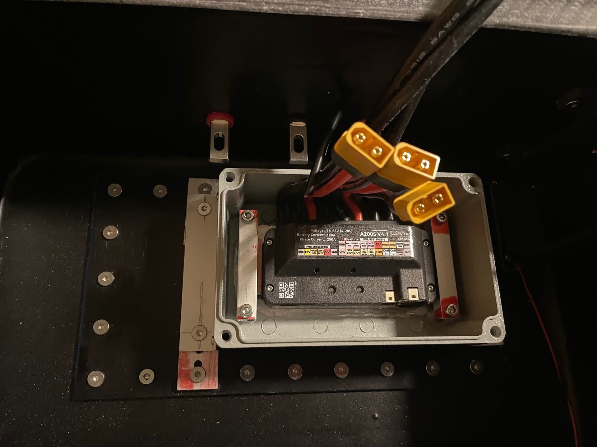
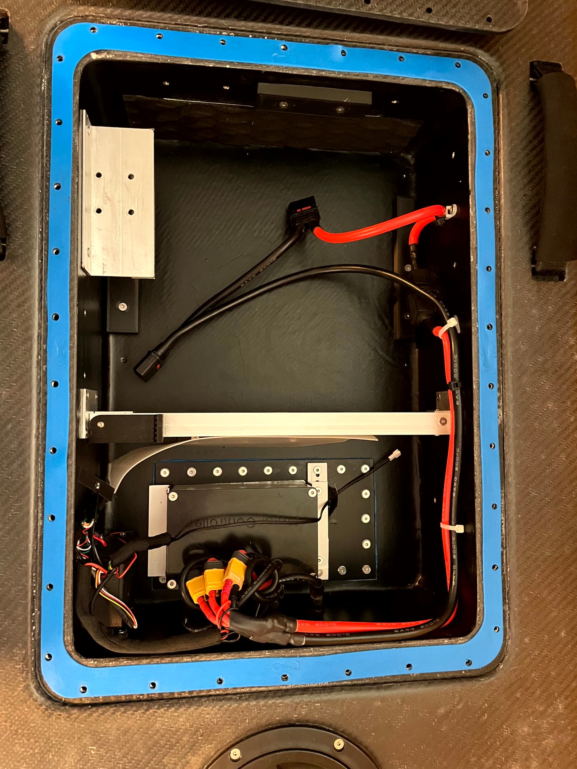
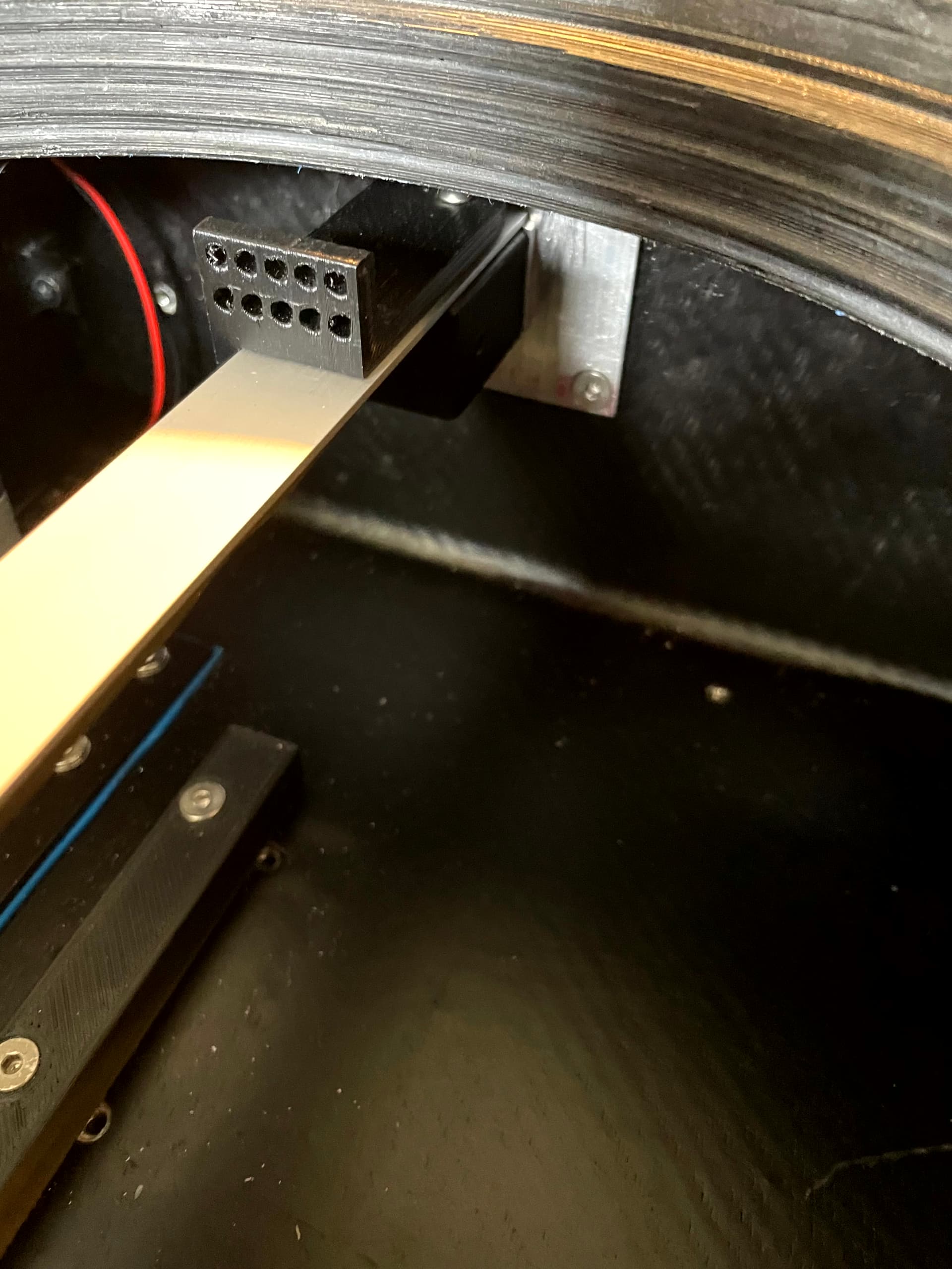
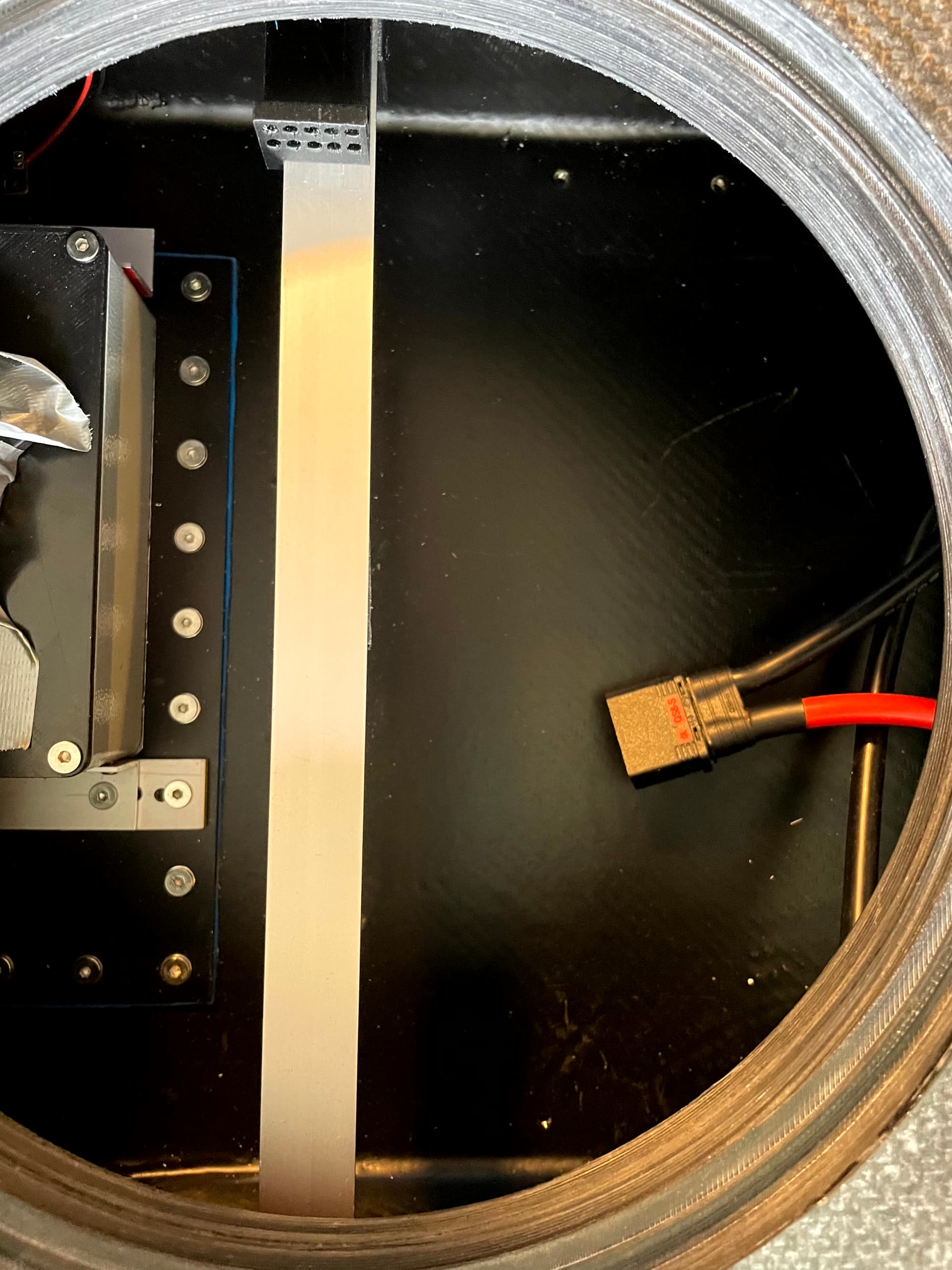
ESC and elctronics
For the ESC I used a VESC A200Sv4.1, a replacement I got from a faulty v3. Not the cheapest option but it is well made and runs cool. To protect it from water, I put it in an extra aluminum case. The case is not 100% waterproof as I could not bother with cable glands. The compartment is waterproof, it is just an extra safety measure if some drops should get in. There is a 0.5mm heat pad between the ESC and the case. Between the case and the heat sink, there is only a thin graphite heat transfer foil, as the surfaces are flat. I lathed down the painting on the outside of the case. On the inside I just “machined” it on a drill press. The passive cooling works well, the VESC temp never exceeded 40°C so far.
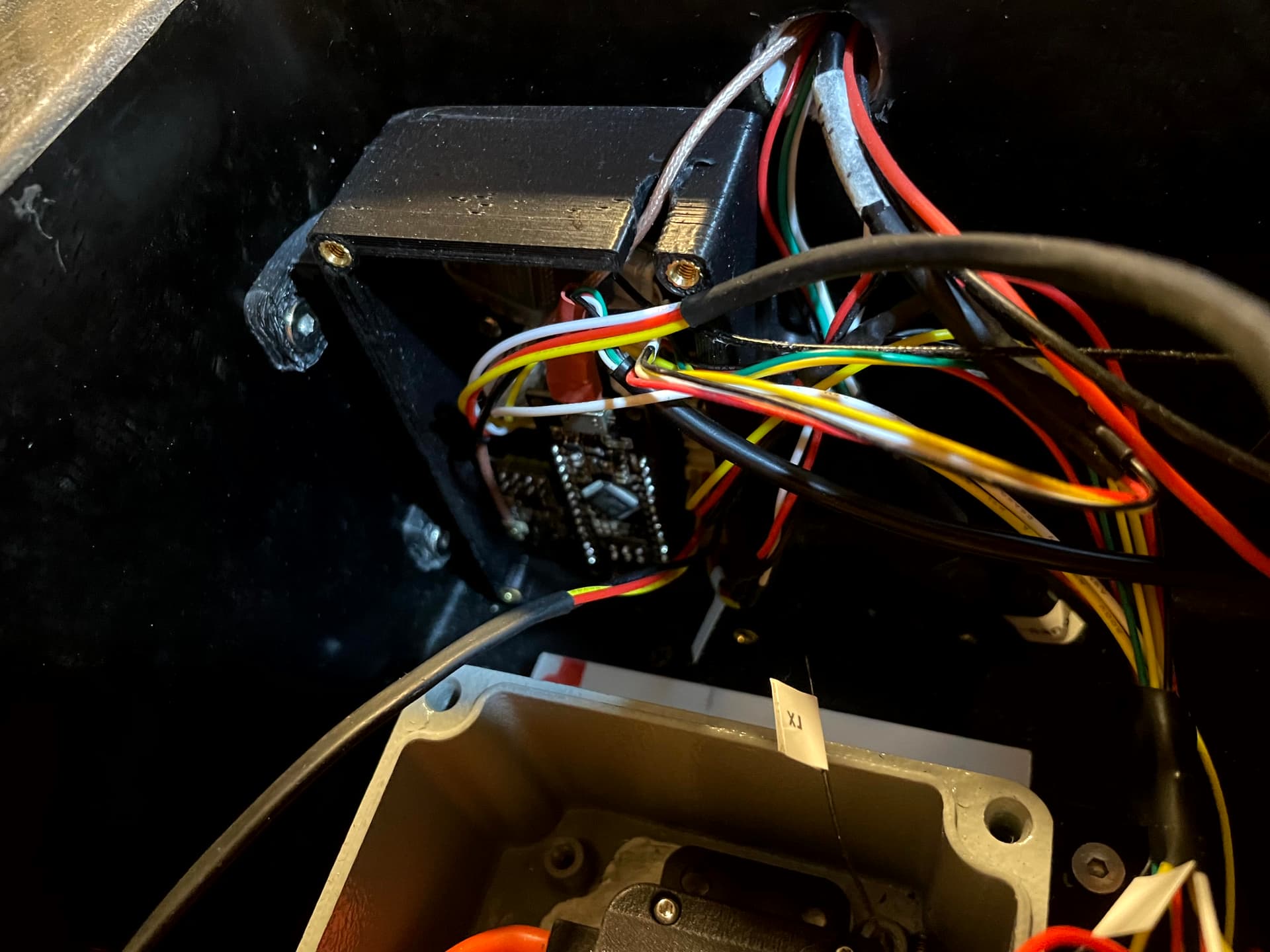
Receiver and Minnie Logger are in a small box below the tube to the front. The loggers GPS module as well as the receivers antenna sit in the front of the board. Minnies BT/WiFi antenna sticks out of the box as it is only needed to transfer log data. I also added NTC temp sensors to the battery packs to log battery temp, it is connected to the motor temp inut of the vesc and logs unter motor temp in metr log.
2 Likes
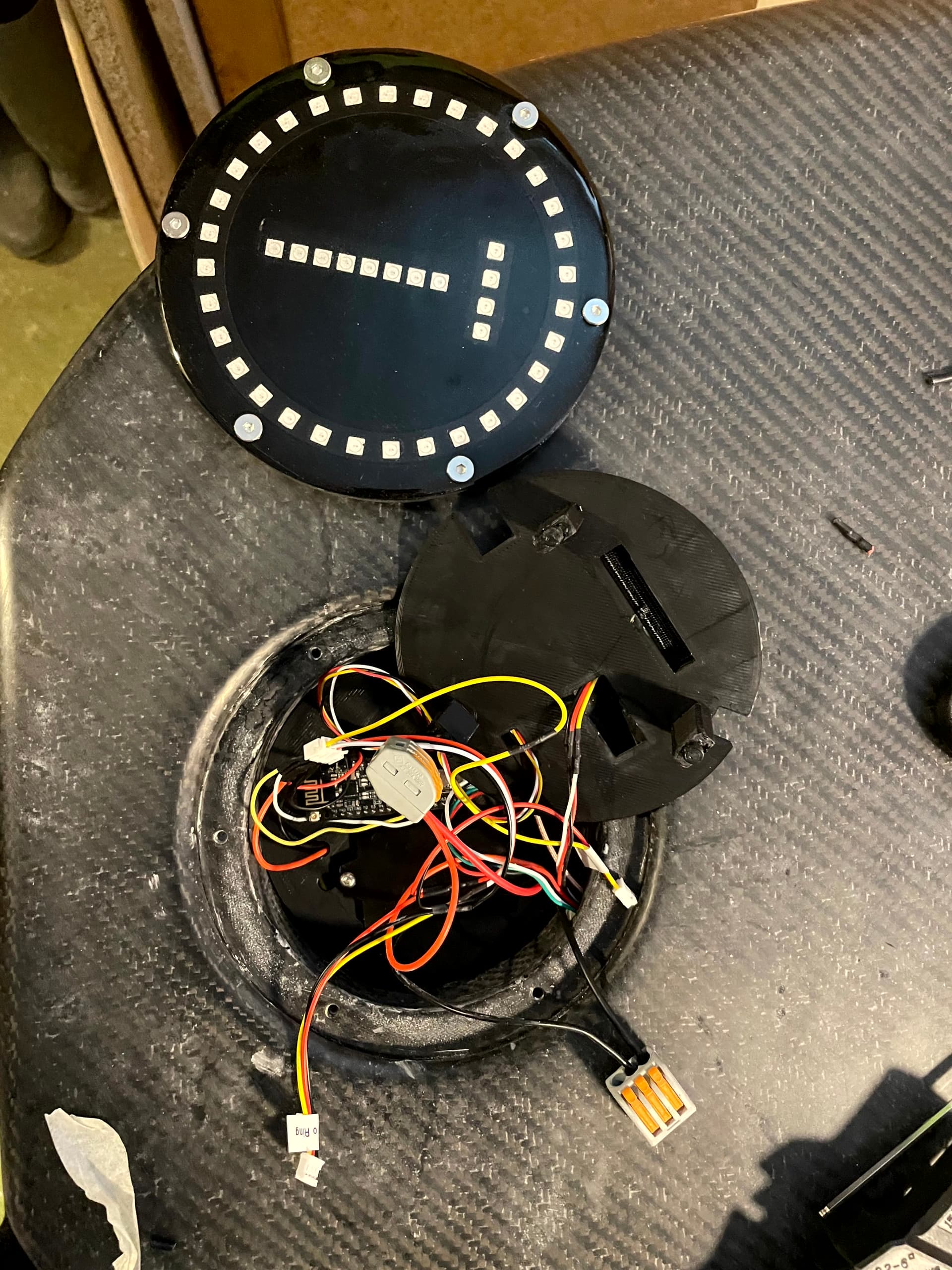
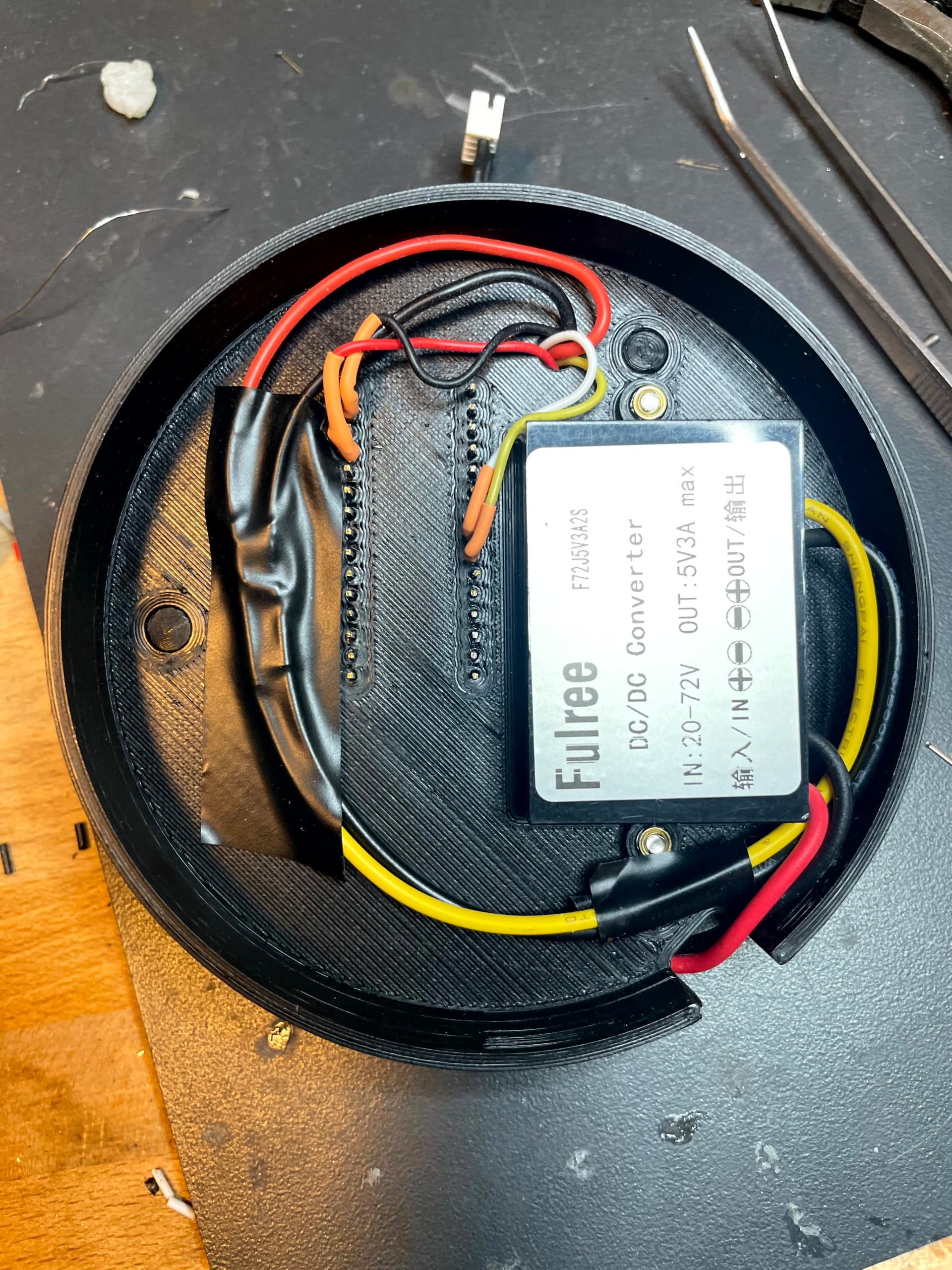
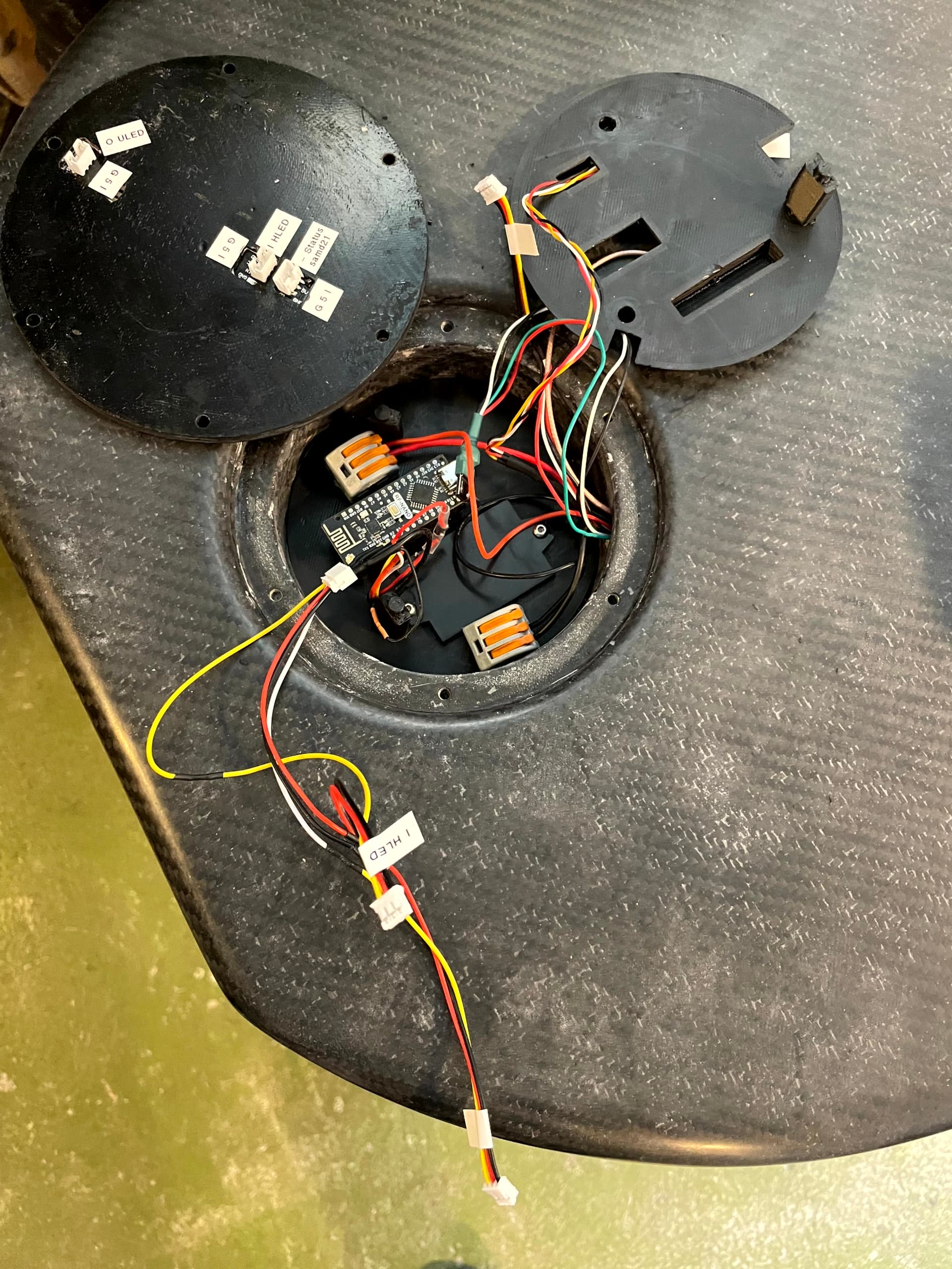
Gadgets
As it is hard for me to read the display of the remote, I added some LEDs to display the voltage level of the battery. I built it into the lid of the receiver antenna compartment in the front of the board. I is made from a 32 segment 2812b RGB LED ring connected to an arduino.
The second feature is the flightAssis height measurement system. The vertical 8 LED bar indicates the height from the water level. There is an extra 5V 3A DCDC converter to supply the LEDs.
The horizontal 4 LEDs are status indicators. The lid is made from a sandwich covered with dyed fiberglass to allow radio signals to pass. The LEDs are really bright and readable in sunlight.


13 Likes
Holy High Tech Batman!! ![]()
![]()
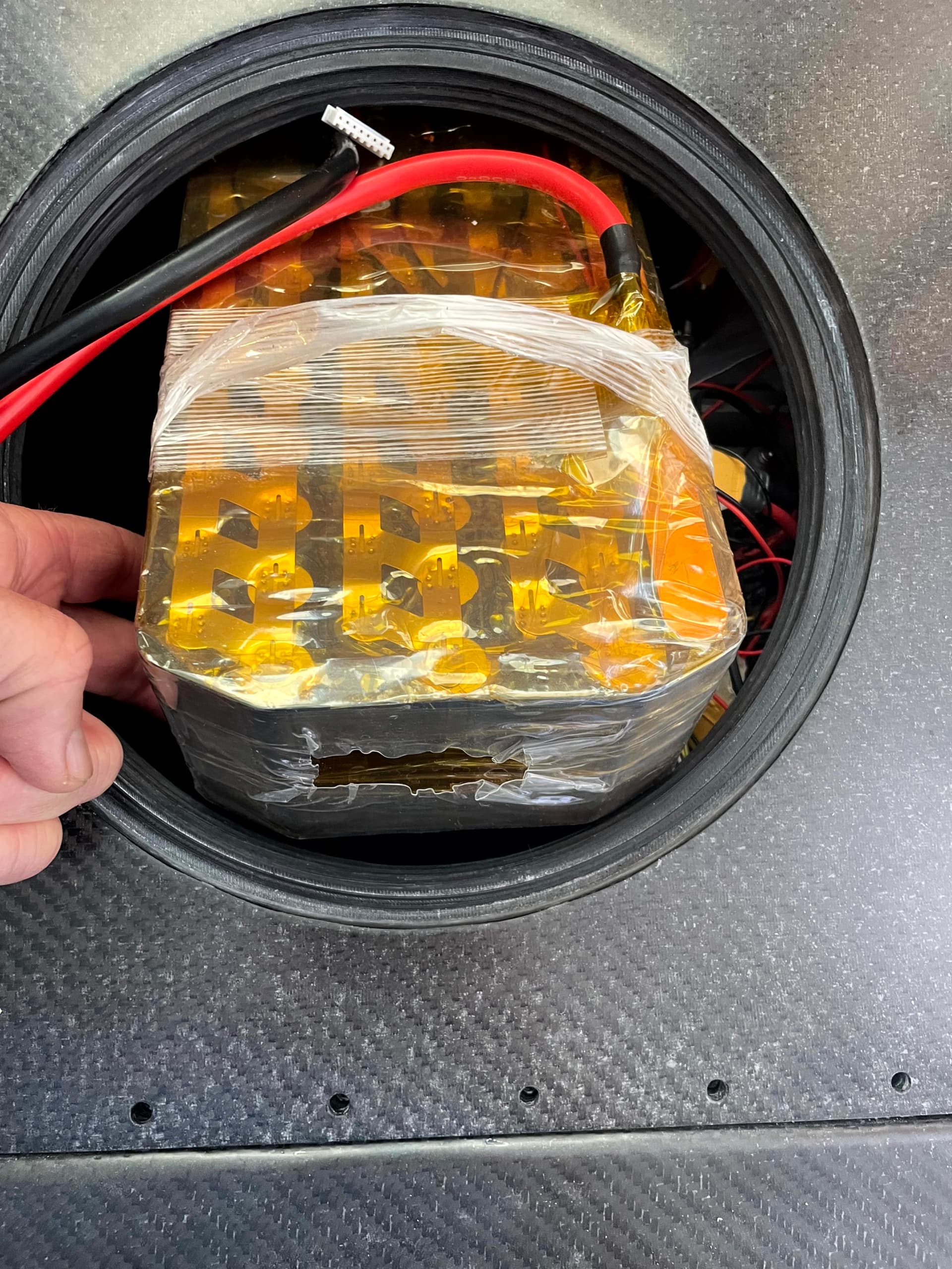
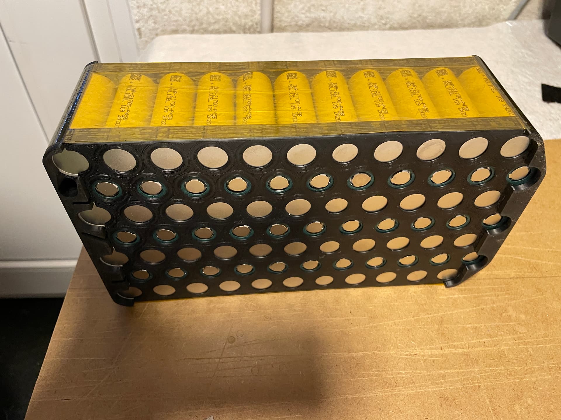
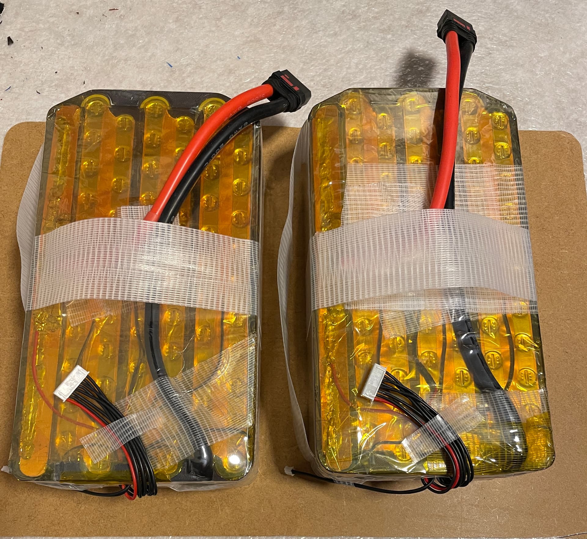
Batteries
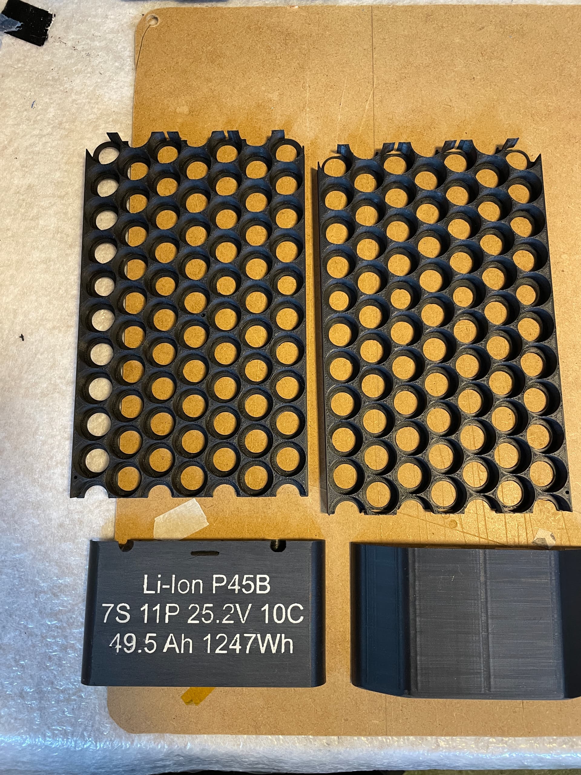
I built two 14S11P Split Packs, one with Molicel P42A and one with P45B. To make them fit the through the screw hatch, I used a offset pattern for cell arrangement. I designed an Printed the cell holders and end caps. 7S is a bit more tricky than 6 (or 8S), as one of the busbars has to be at the bottom of the pack. I used 0.2mm nickel strips to spot weld the packs. Terminal leads are 6AWG with QS8 antispark connectors. I also put an ntc inside to log the battery temp (connects to motor temp input of vesc and logs as motor temp in metr).
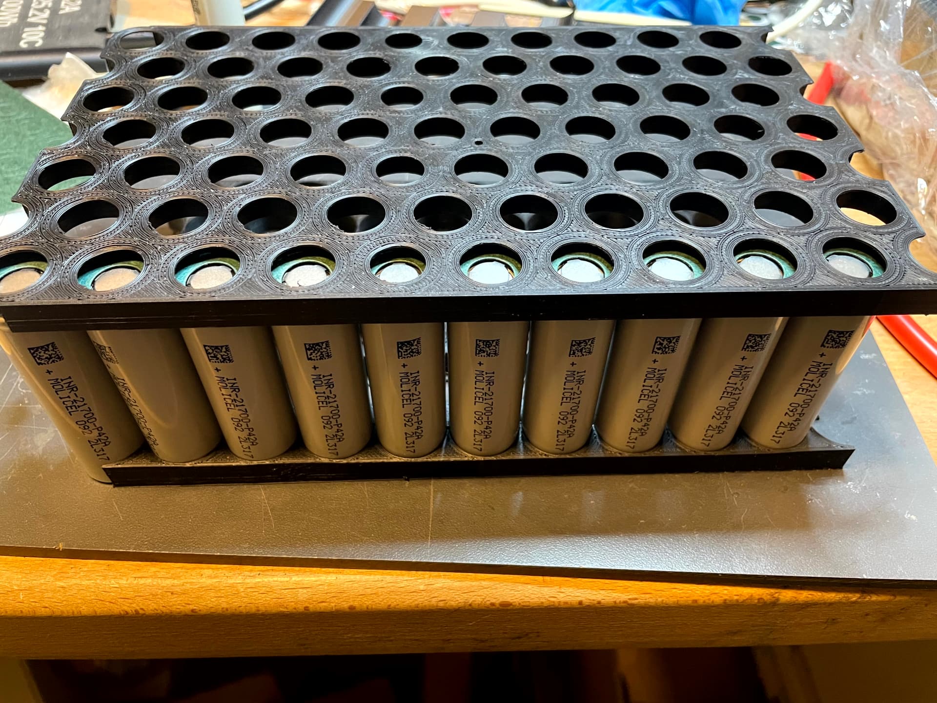
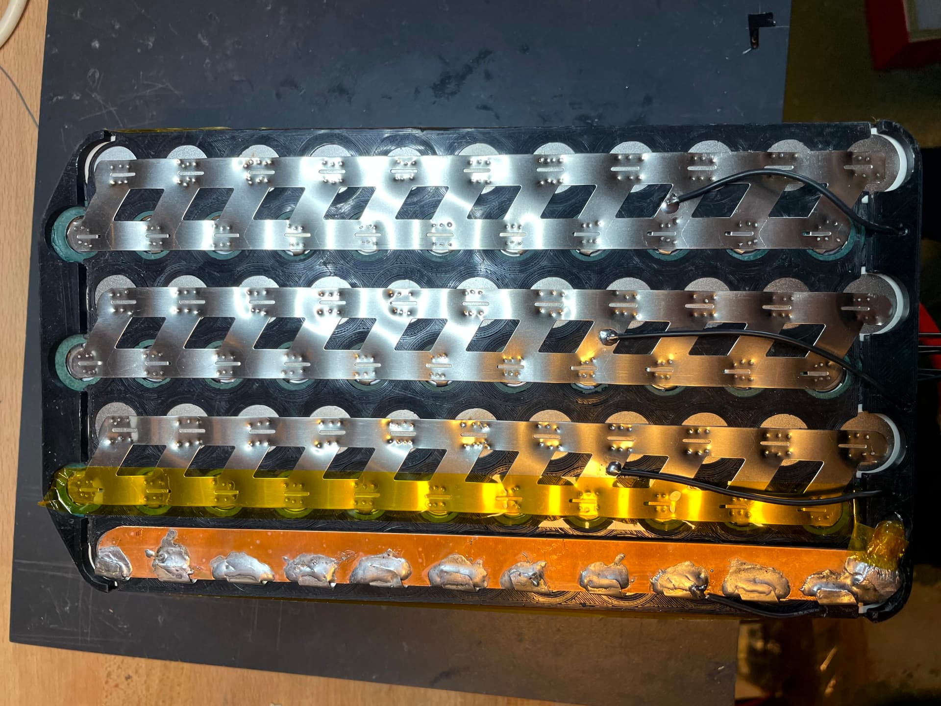
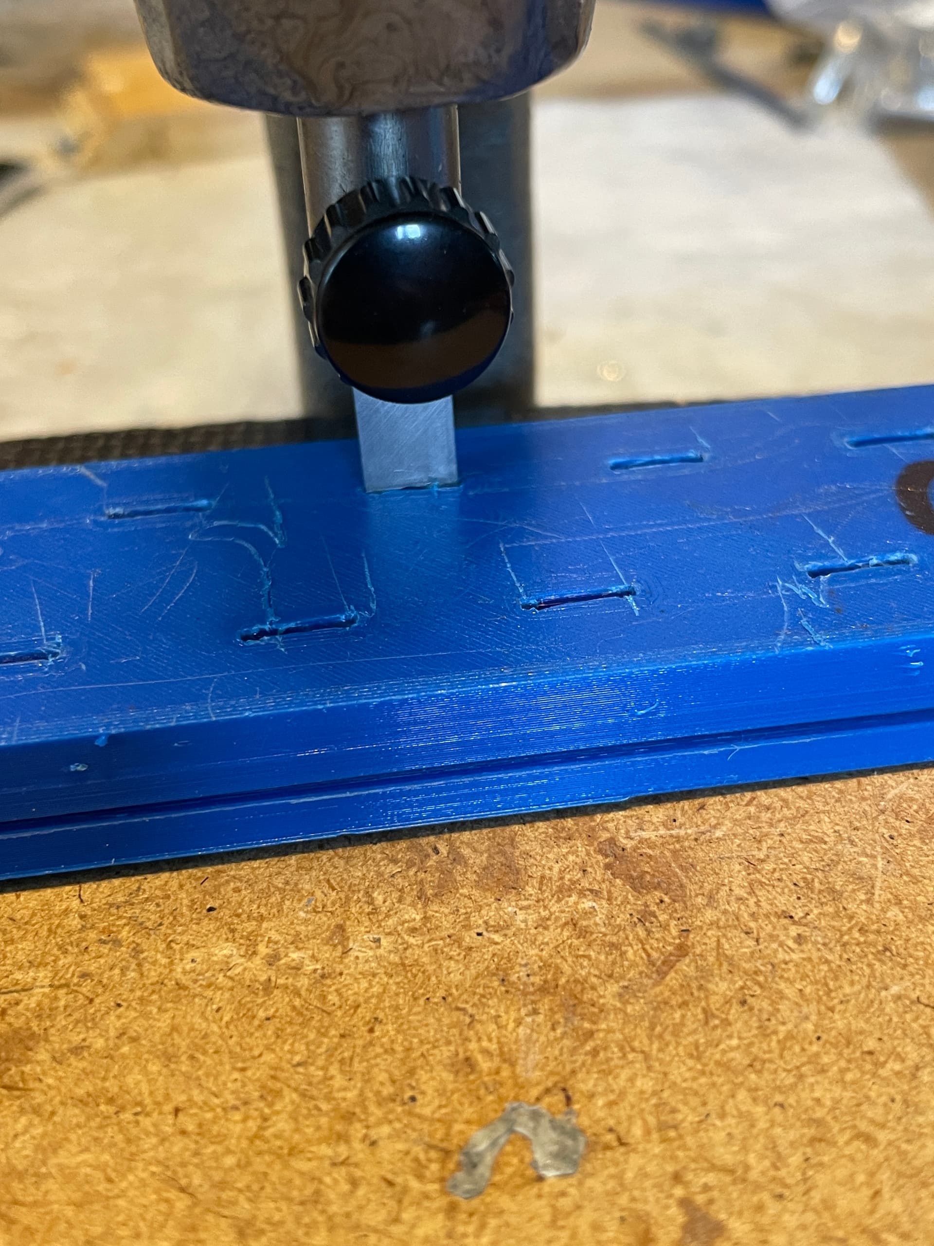
I didn’t like the way the strip got bent to the poles of the cells so I built a 3D printed press template to create a recess.
2 Likes
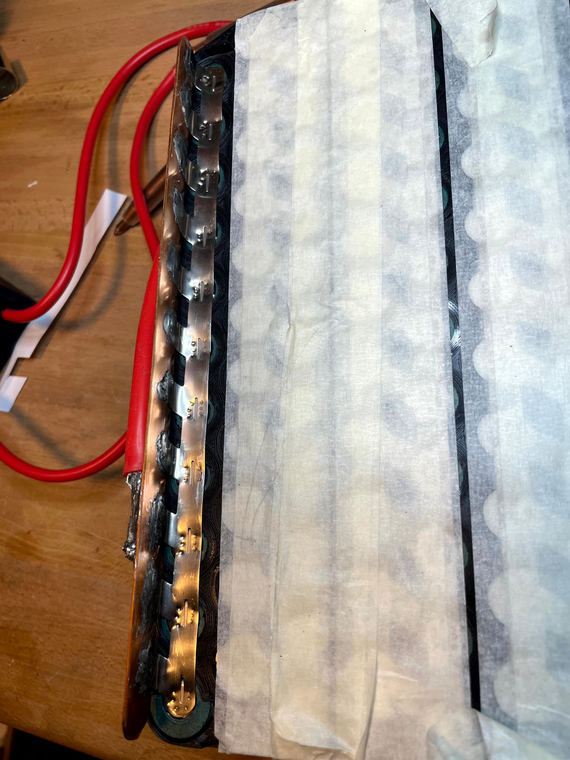
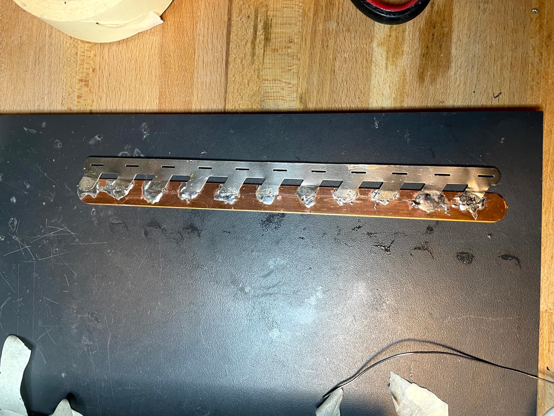
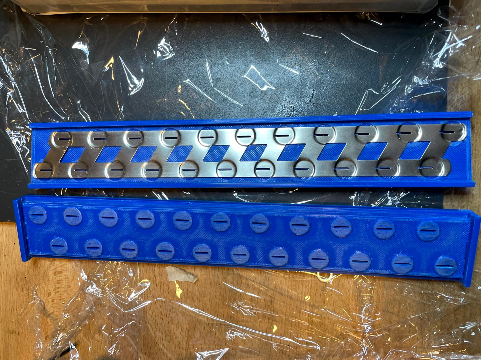
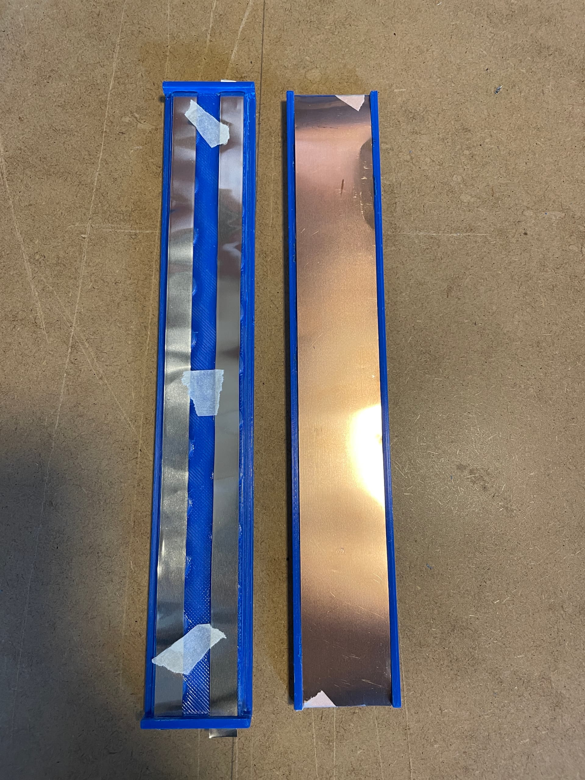
2nd set of Batteries
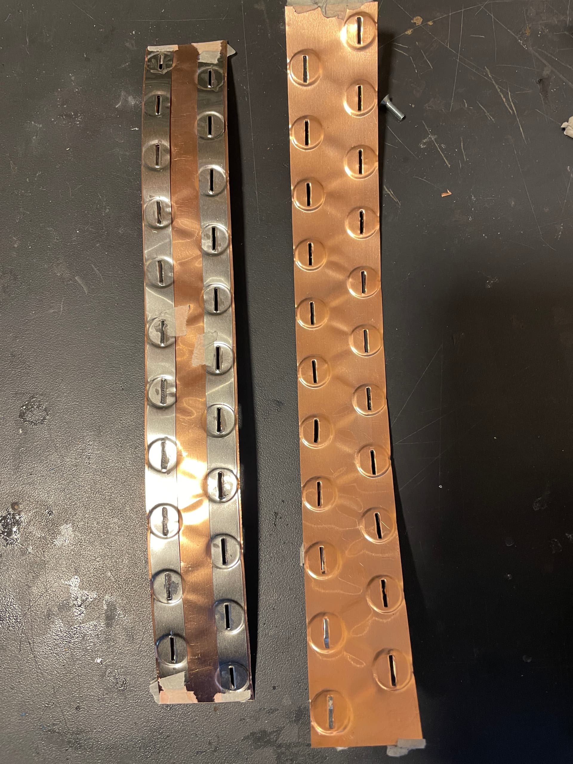
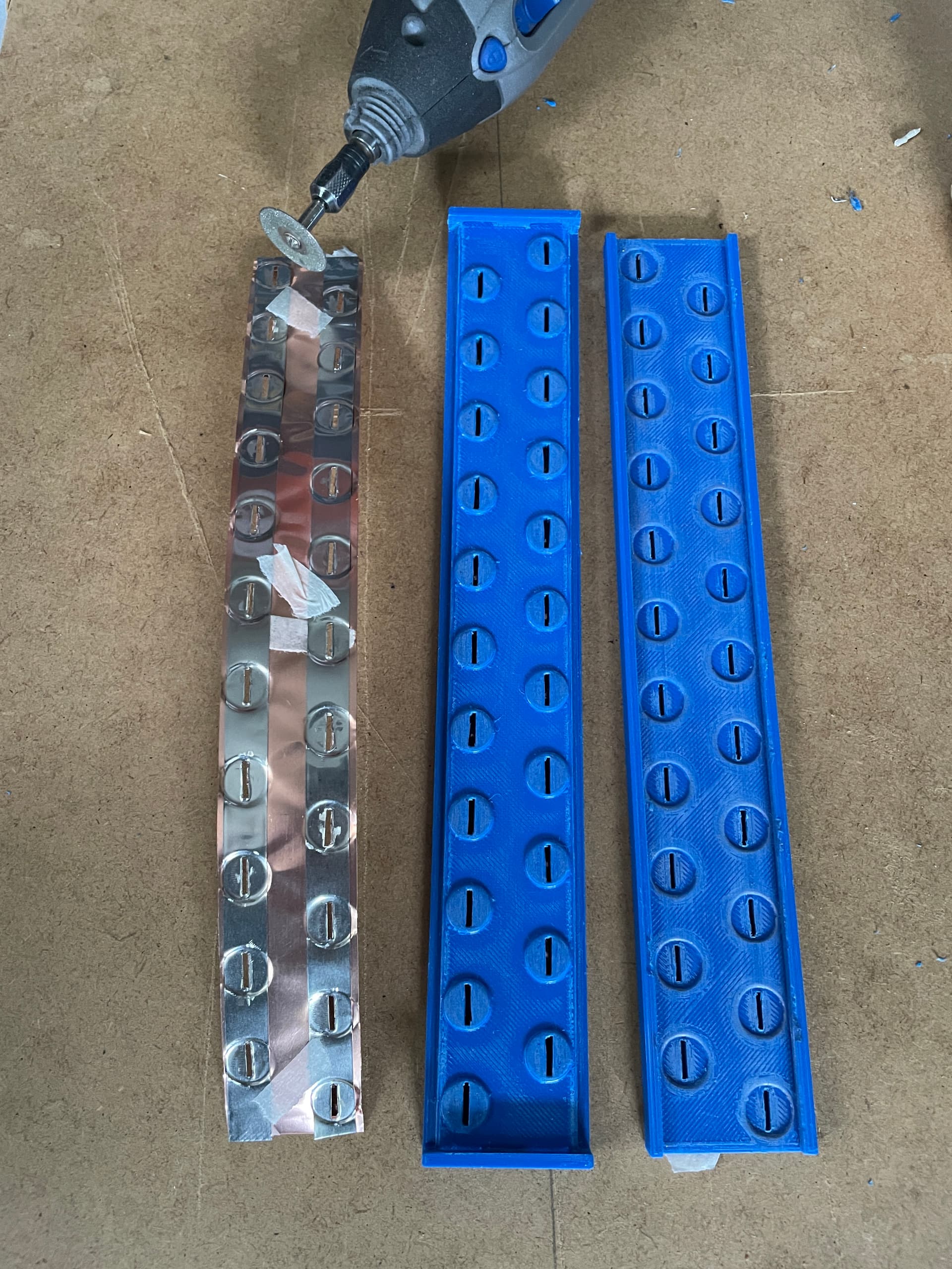
For the second set I wanted to try something new, a copper nickel sandwich. It consists of a 0.1mm copper strip and 0.1mm nickel on top. I used a 3d printed template to form the strip and guide the stamp to stamp out a slot. Conductivity of copper is aprox. 4 times better than that of nickel.

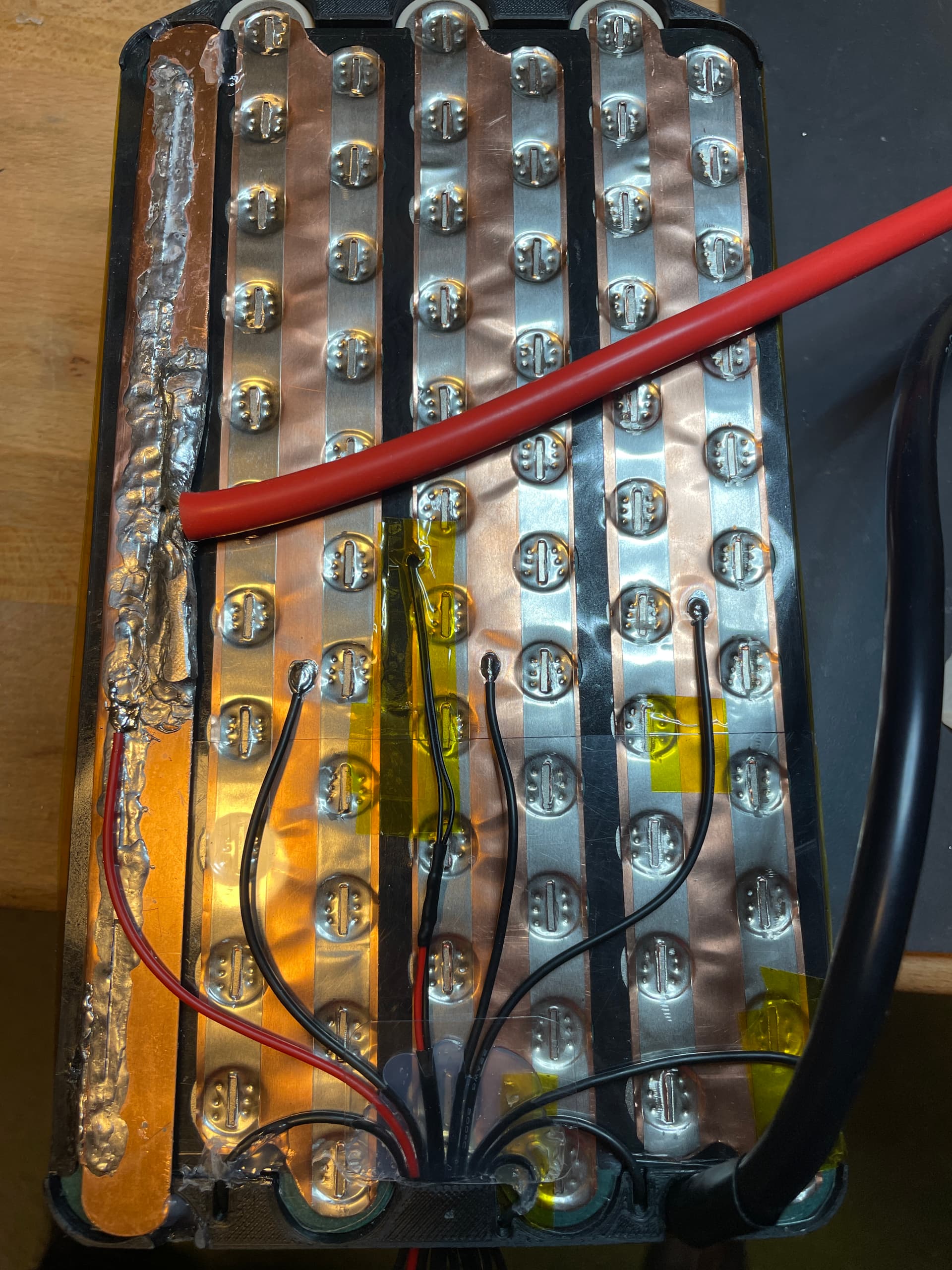
3 Likes
I tested both battery sets and they work well, the P45B has slightly more capacity but not much, only 10% more. For a pack of this size it is not really worth the extra cost. For a configuration where you need high current per cell there might me an advantage to use the P45B.
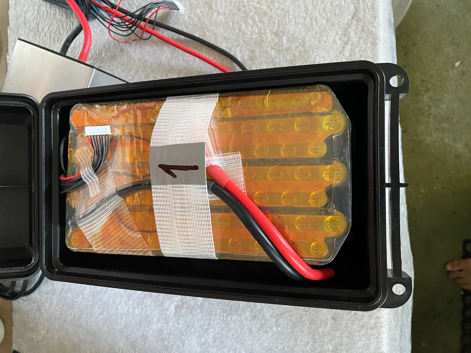
Battery fixing system
I was tired of hock an loop bands so I chose a different way to fix the batteries. There are 3d printed thresholds on the side and at the back to keep the packs in position. The edge of the pack in the back is secured with a angled lever with 5mm pins. The pin locks with a spring on one side. It can be removed wit a 3d printed slider. All parts under load are made from aluminum, the 5mm pins are from stainless steel.
6 Likes
Impressive and artistic build!
On your RL mast have you had the need or considered bonding the RL mast to RL mast plate? I find that there is a tiny bit of flex there using only the two mount screws and was thinking to inject epoxy or JB weld cement and steel bonding agent into that connection to remove flex and lock it tighter.
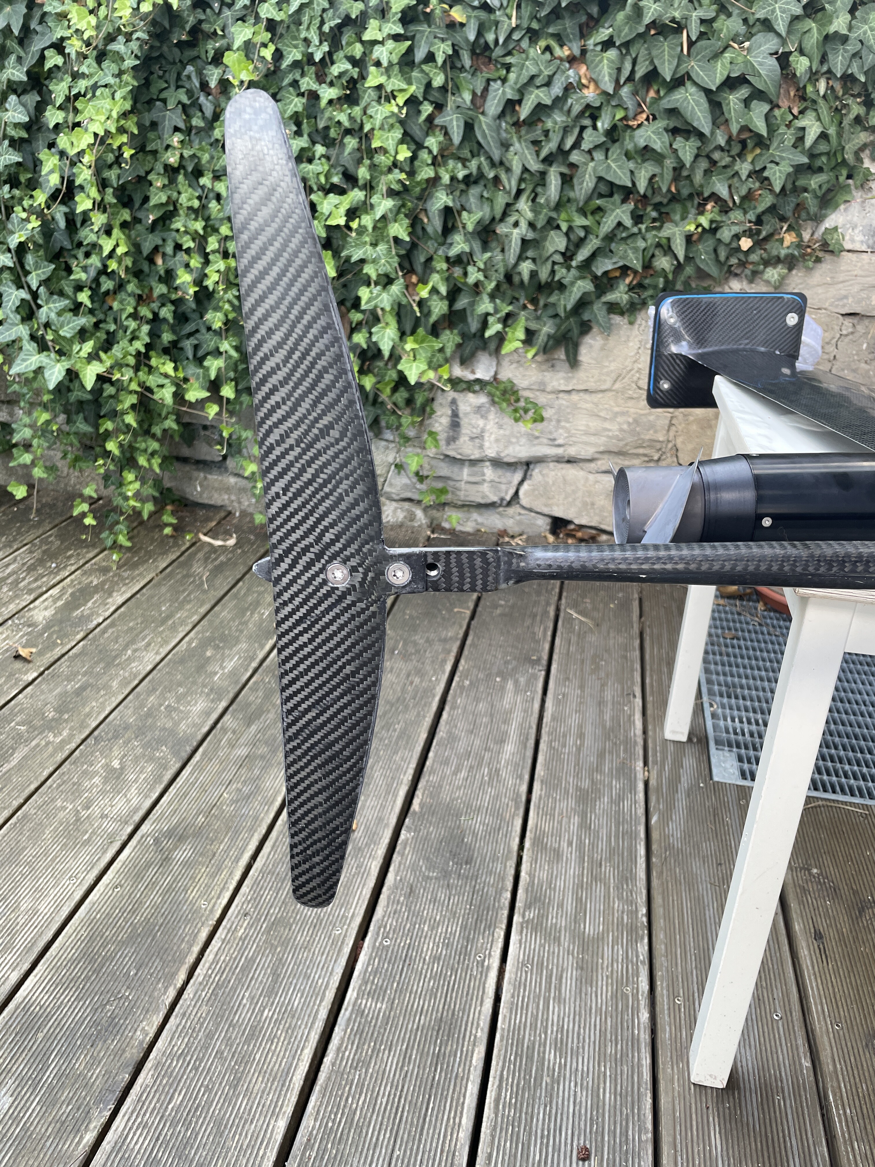
In this build I built my own mast from CFK. In my first build I only used the RL Fuselage and wings, not the mast, I used a chinese slinshot knockoff, which is really solid (and heavy). I do have an RL mast but never used it. I think the RL mast is not the most rigid one on the market, not only the junction between mast plate and mast but also rigidity of the mast itself. But it is relatively low cost, to be fair.
When sketching masts i found the the rl mast has the same profile as the f1 but rl is about twice the thickness. Maybe the grade of alu can be lower on the rl but i think it’s definitely not the flexiest mast out there. Gong v1 mast comes to mind ![]()
Nice build!
1 Like
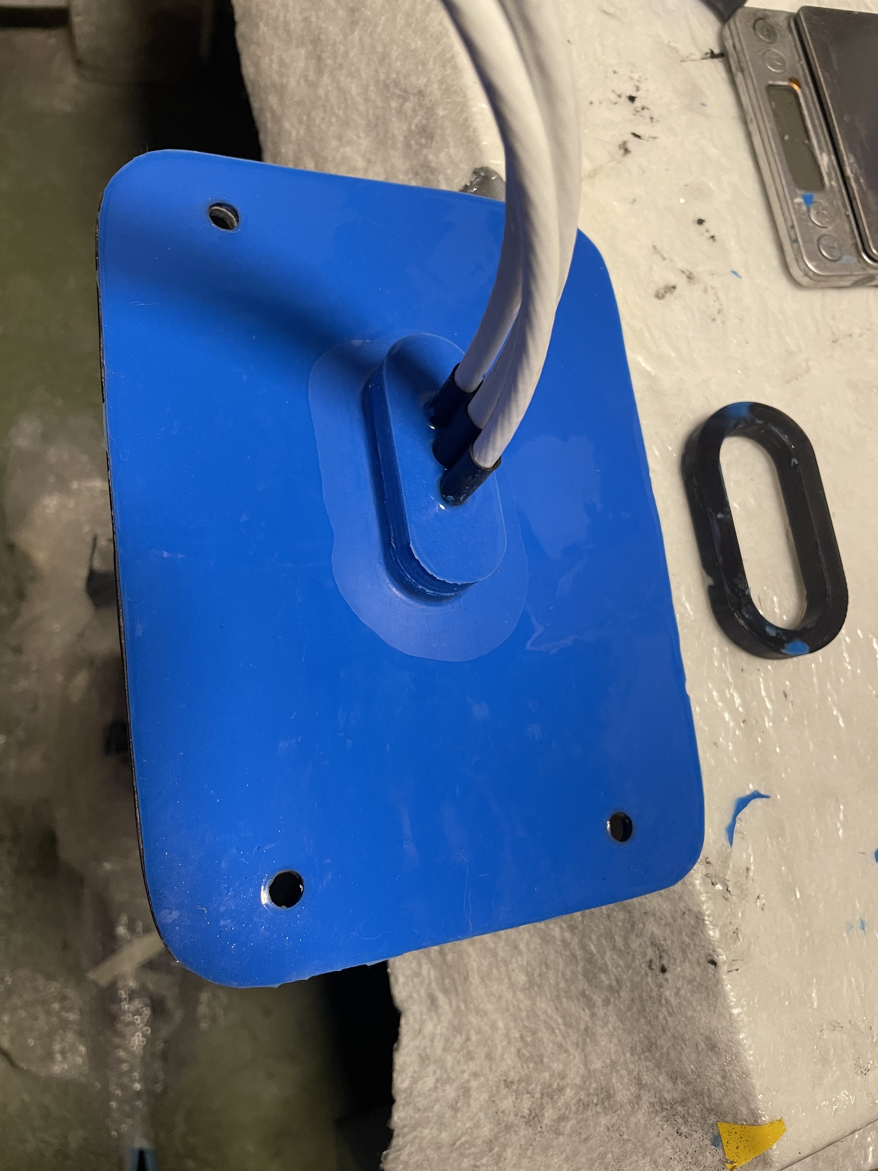
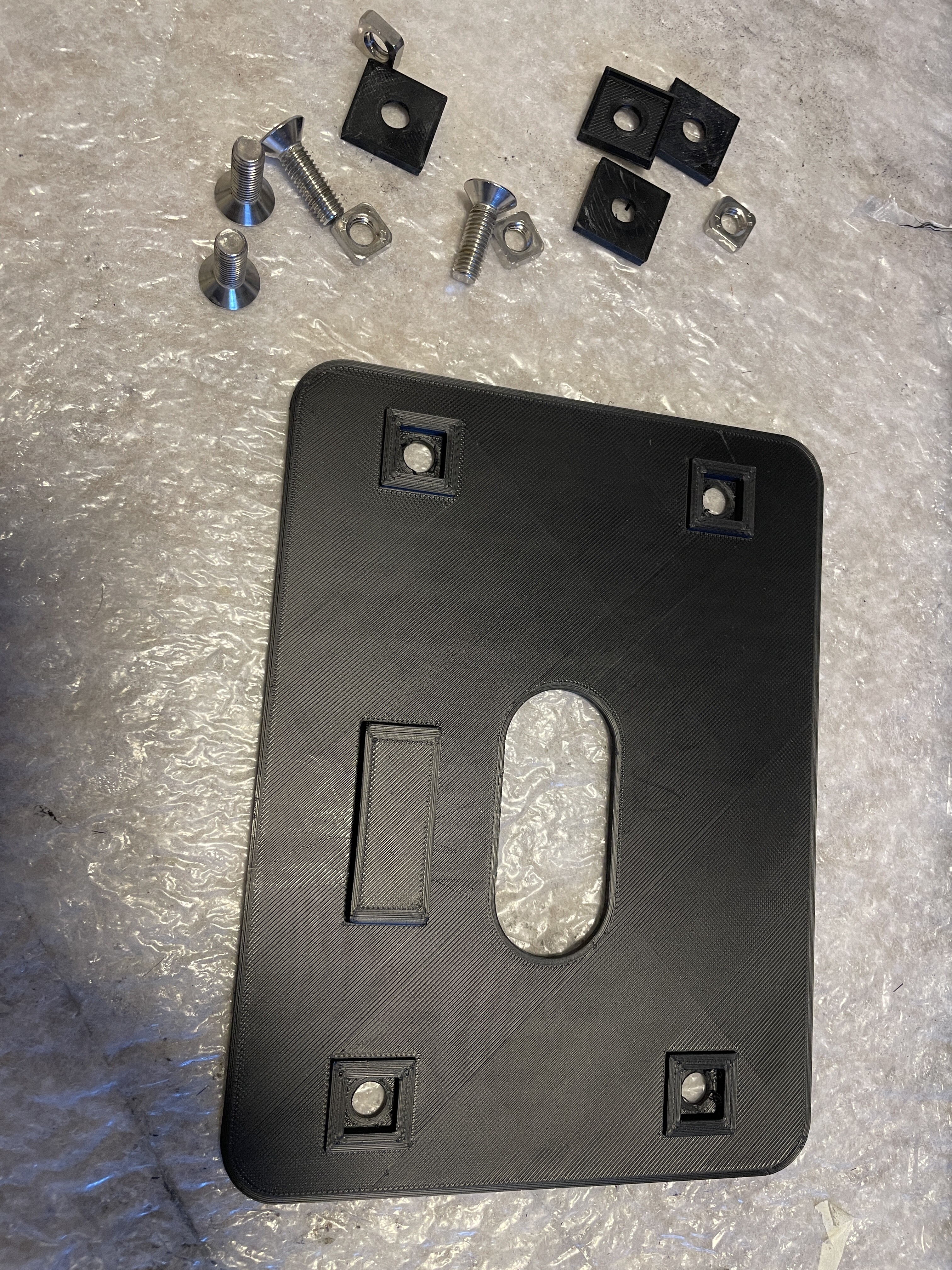
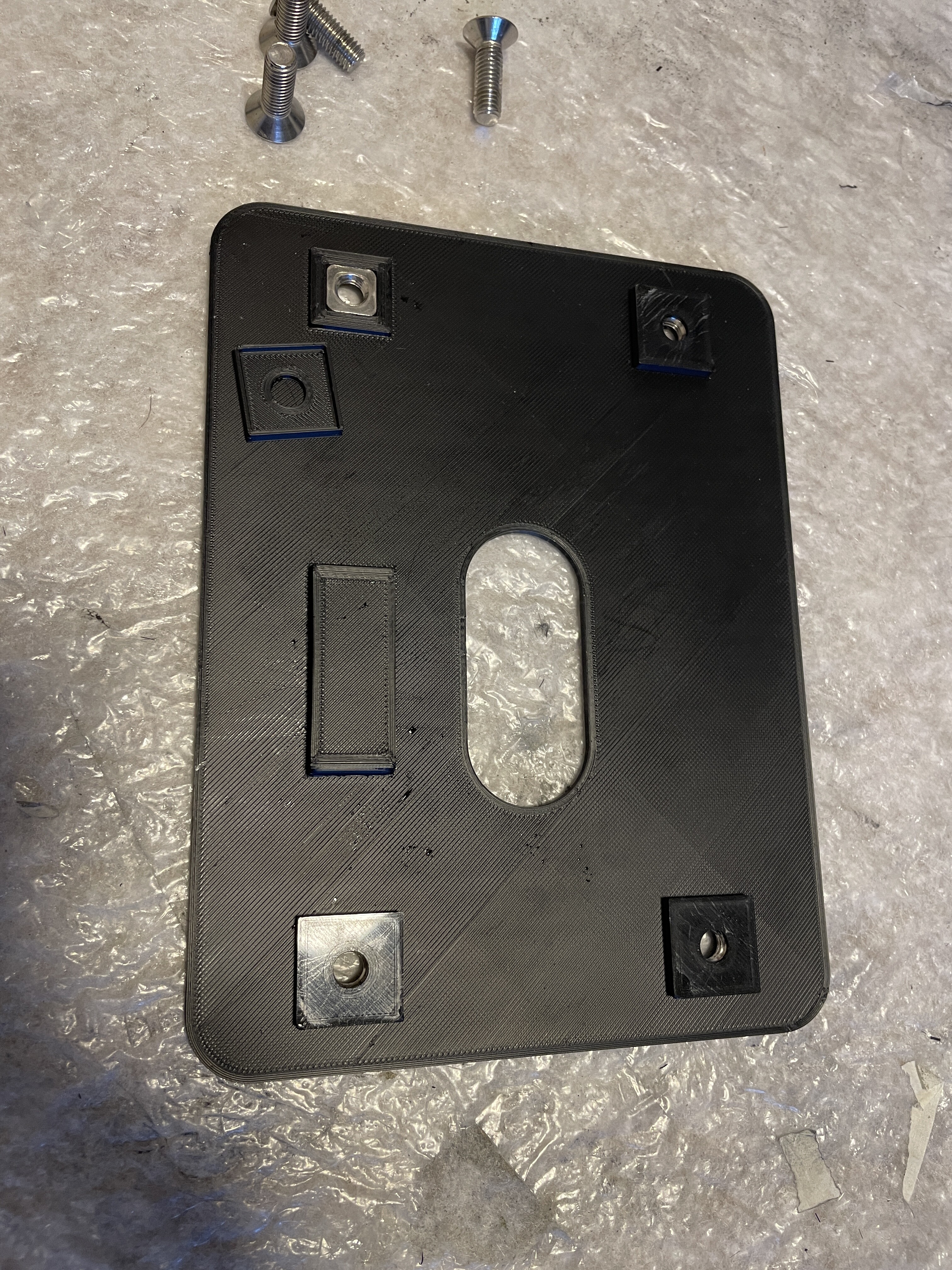
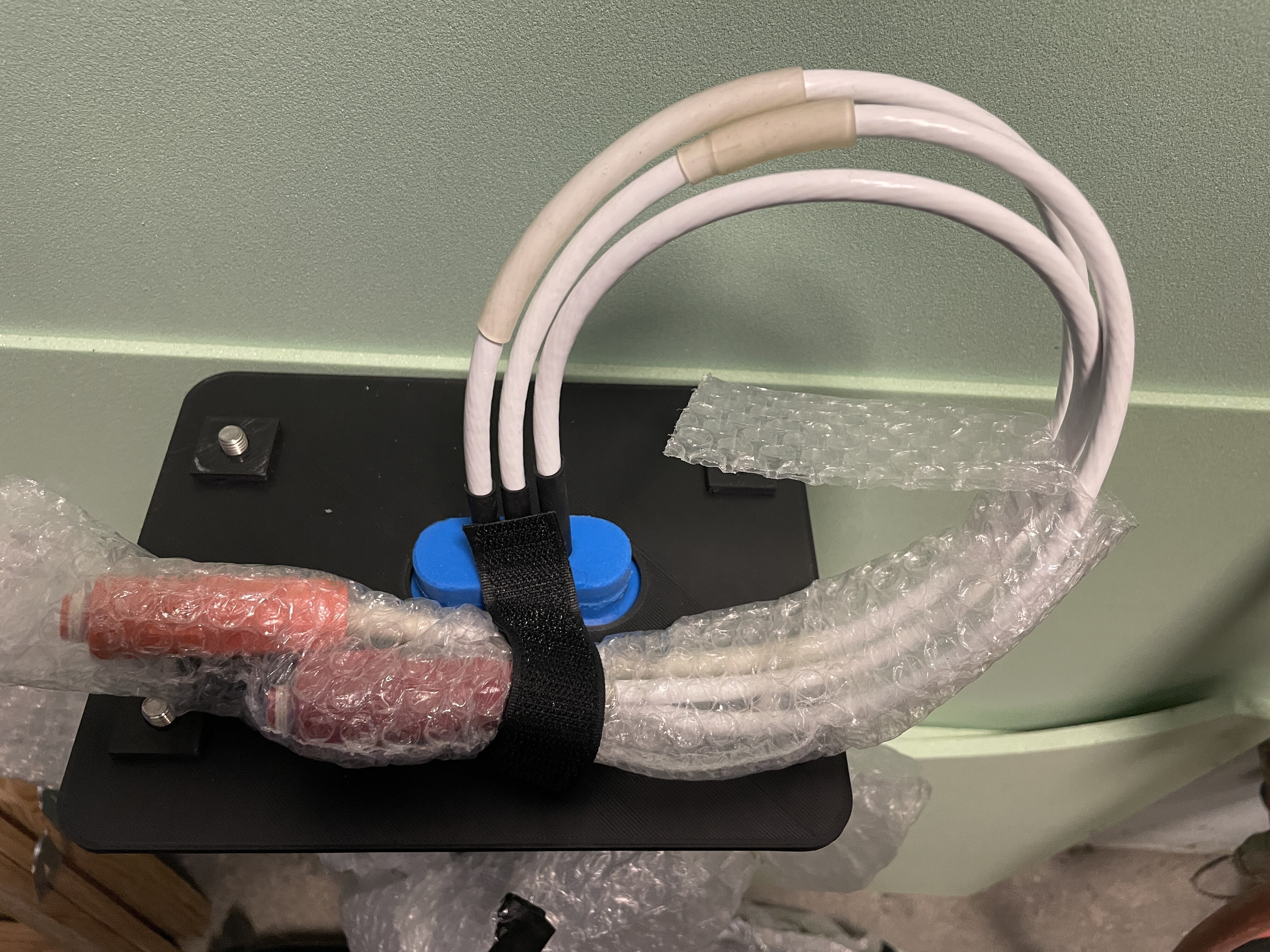
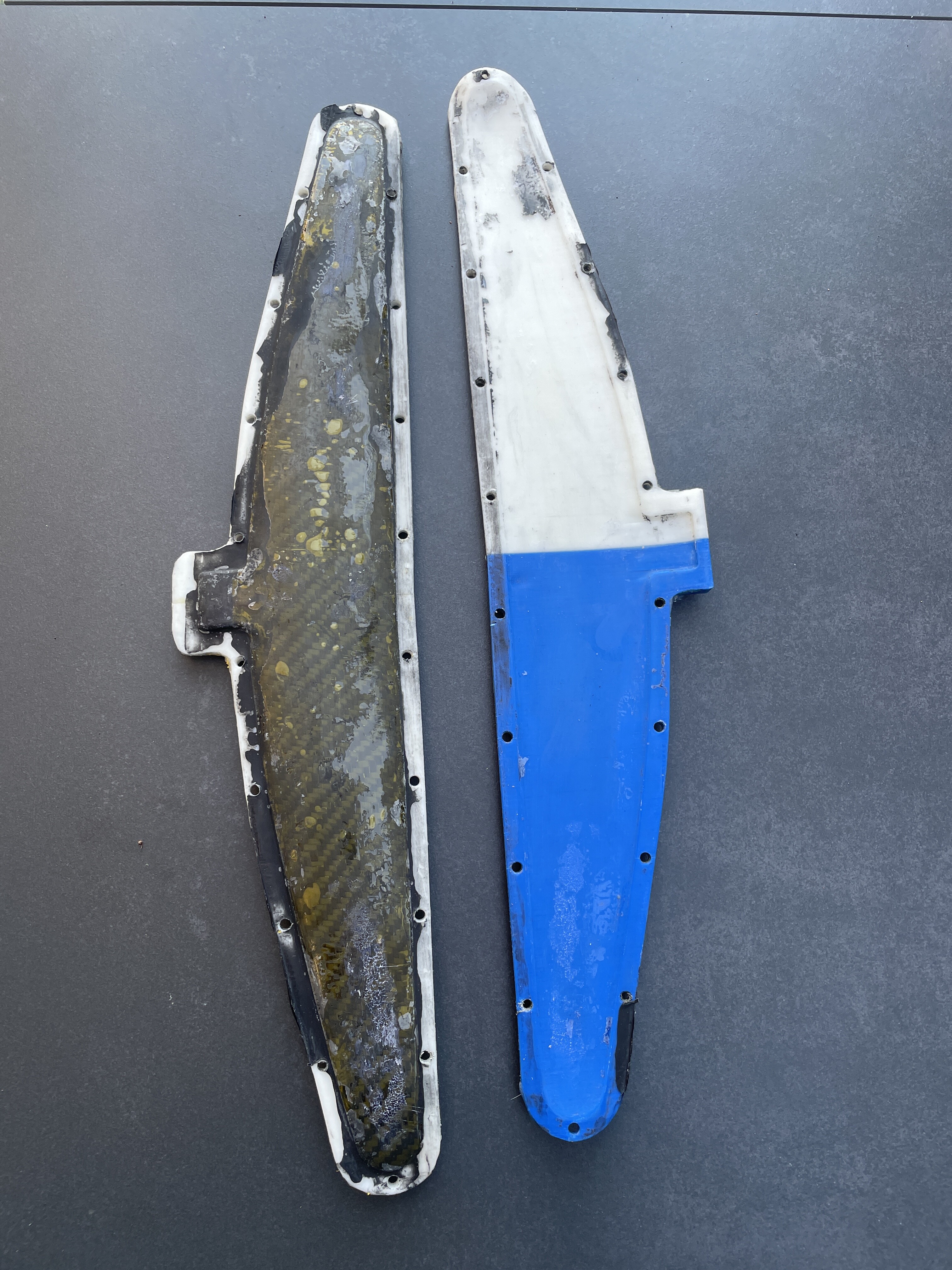
Built a top cover plate for the mast for transport. This keeps the Wagnersil silicone seal in place and allows to fix the phase cables. It also “stores” the fixing screws.
I also need to build a part to secure the motor for transport as this is the most delicate part of my system. The motor is over 2kg and has quite a bit of lever force. Still thinking on how to build an easy to remove sopport for the motor…
2 Likes
Season is ending, time for a 1st conclusion. I made around 600km on the new board and really like it. If I’d start over I would build the mast slightly angeled to the front to get a better foot position, I have to stand rather far in the back. 10-15cm more to the front would be nice. I extended the fuselage 7cm to the front which helped.
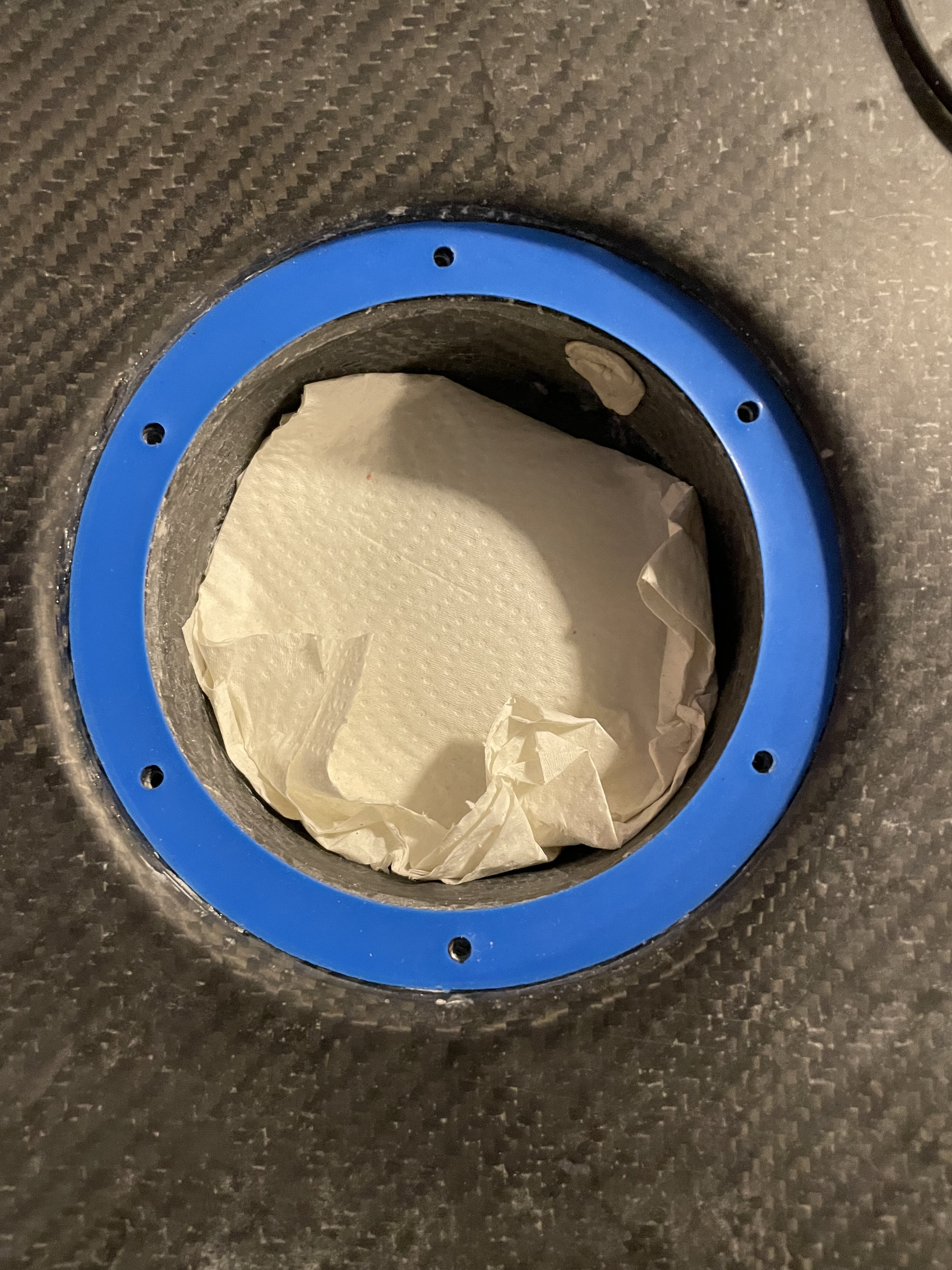
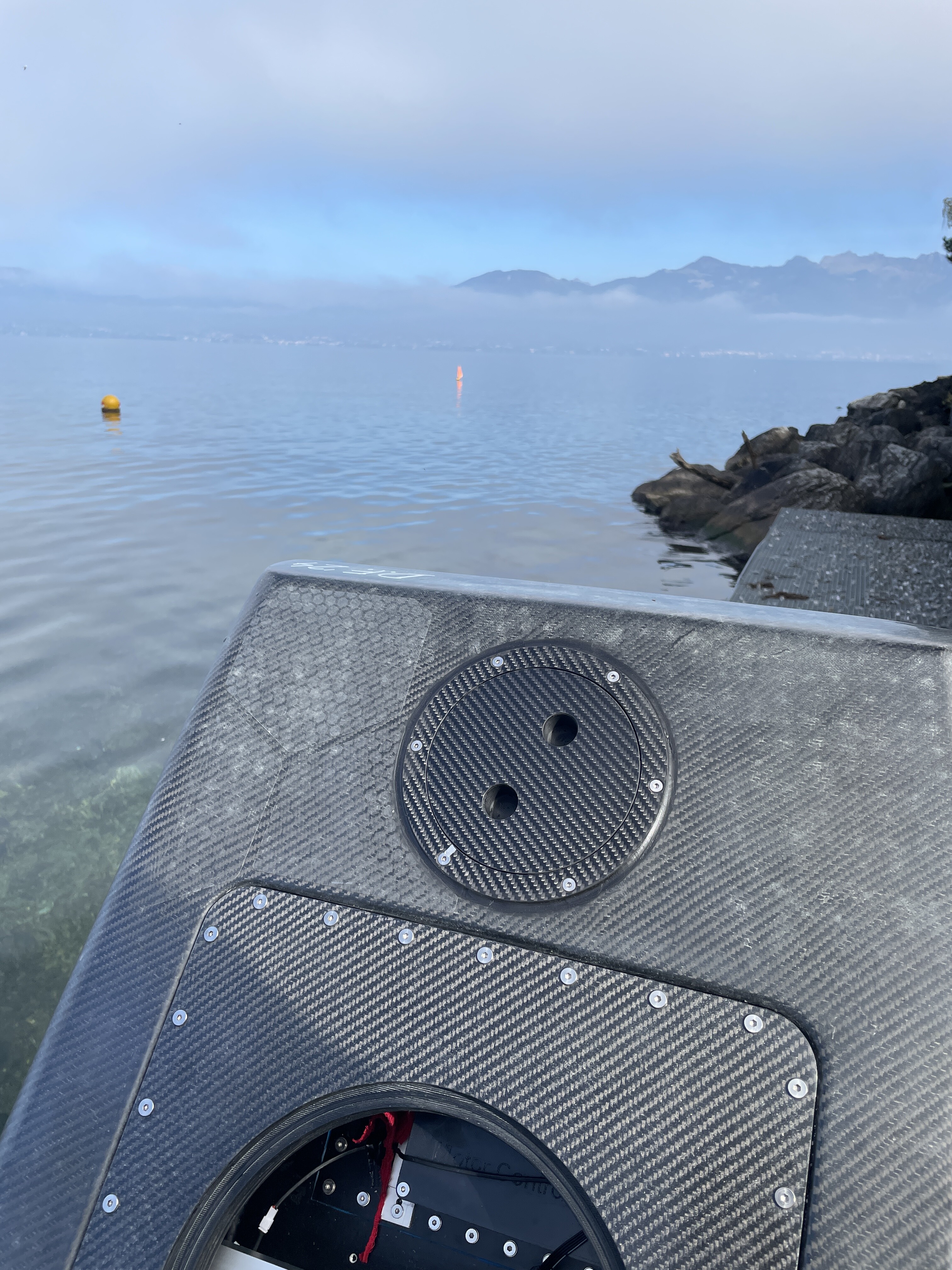
Because of the foot position a bit far back, I have to stand partly on the lid of the rear hatch (the one used to connect the motor cables). The round Osculati hatch was sticking out too much and not nice to stand onto. I built a custom hatch that only stands over 2mm over the board. It is also waterproof, as oposed to the Osculati. Not a big problem as the connectors are also waterproof but extra weight in the board.
Tested differen props, 3 blade FR6”, 2 blade FR 7” and Flight prop. They all work well but I prefer the flight prop, very efficient and fast.
I also built a new smaller rear wing with 187cm2.
New rear hatch
2 Likes
I really like your builds. You work to a level of perfection that I’ve come to expect from myself. You’re not satisfied with anything and you’re always improving your own things. Keep it up ![]()
2 Likes
I looked at your molds for the rear wing. They are 6 mm thick. I am designing my own molds for the front and rear wings. The mold for the front wing will be printed in PLA in several parts. Do you think 6 mm will be enough for the front wing mold or should it be thicker?
When vacuum bagging, you use pressures from -0.6 to -0.8 bar. I used to think that -0.3 bar would be enough. But apparently I found this information for laminating EPS or XPS boards. I have never used vacuum bagging yet. I am still assembling the rig for it. Do you use a special resin? Will normal epoxy resin not suffer at such low pressures? Bubbling, boiling or something like that?
For the front wing I would use 8-10mm thickness of the molds, depending on the wing size, for the back wing even 5mm is ok. I use esun pla+ which is a very strong material but does not like heat. Be careful with heat blankets and oder heat sources, stay below 30degrees C. For the infill I use 10-15% cubic infill and 3 top/bottom layers and perimeter lines.
For the vacuum -0.3–0.6 bar is OK. When not heated, the molds can withstand -0.8 bar. -0.3 is for laminating soft material like low density eps. For xps I woul stay below -0.5bar (-0.3-0.5). I use a valve to adjust the vacuum, just let in some air until you reach the value you need.
I use normal epoxy with 60min hardener. For bigger parts (like a board) and for beginners I suggest to use a slower hardener like 120min, to have enough time. I even mixed hardeners of the same epoxy system to get an in between processing time. This also works as long as you respect the mixing ratio.
1 Like
Very nice build !
Hi! How long can you e-foiling with that battery ?
as far as i understand, it is connected with the wrong distance from the trailing edge of your board, if the mast was closer to the nose, probably it would not have been necessary to extend the fuselage, right? How did you calculate this distance when installing the mast? I will have to do the same soon, want to be more prepared)