Started almost 3 years ago with my 2nd build. I started with some wings (rear and main wing) to test molding with 3d printed molds.
Rear wing:
the printed mold was glued together and coated with gelcoat, then sanded.
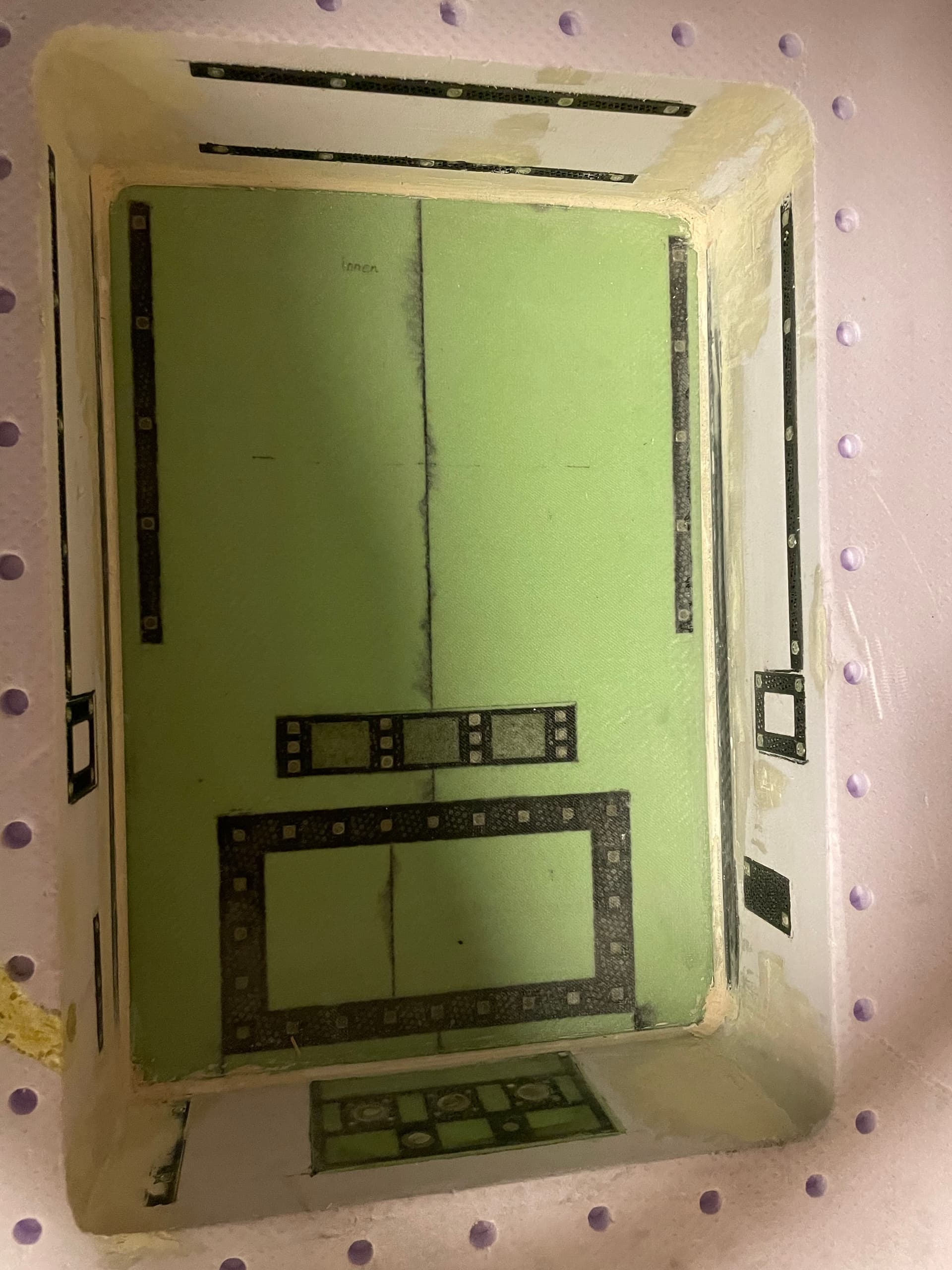
after treating with release agent, gelcoat was applied with a brush. Next 80g glass, when the gelcoat is sticky. Then twill and biax layers.
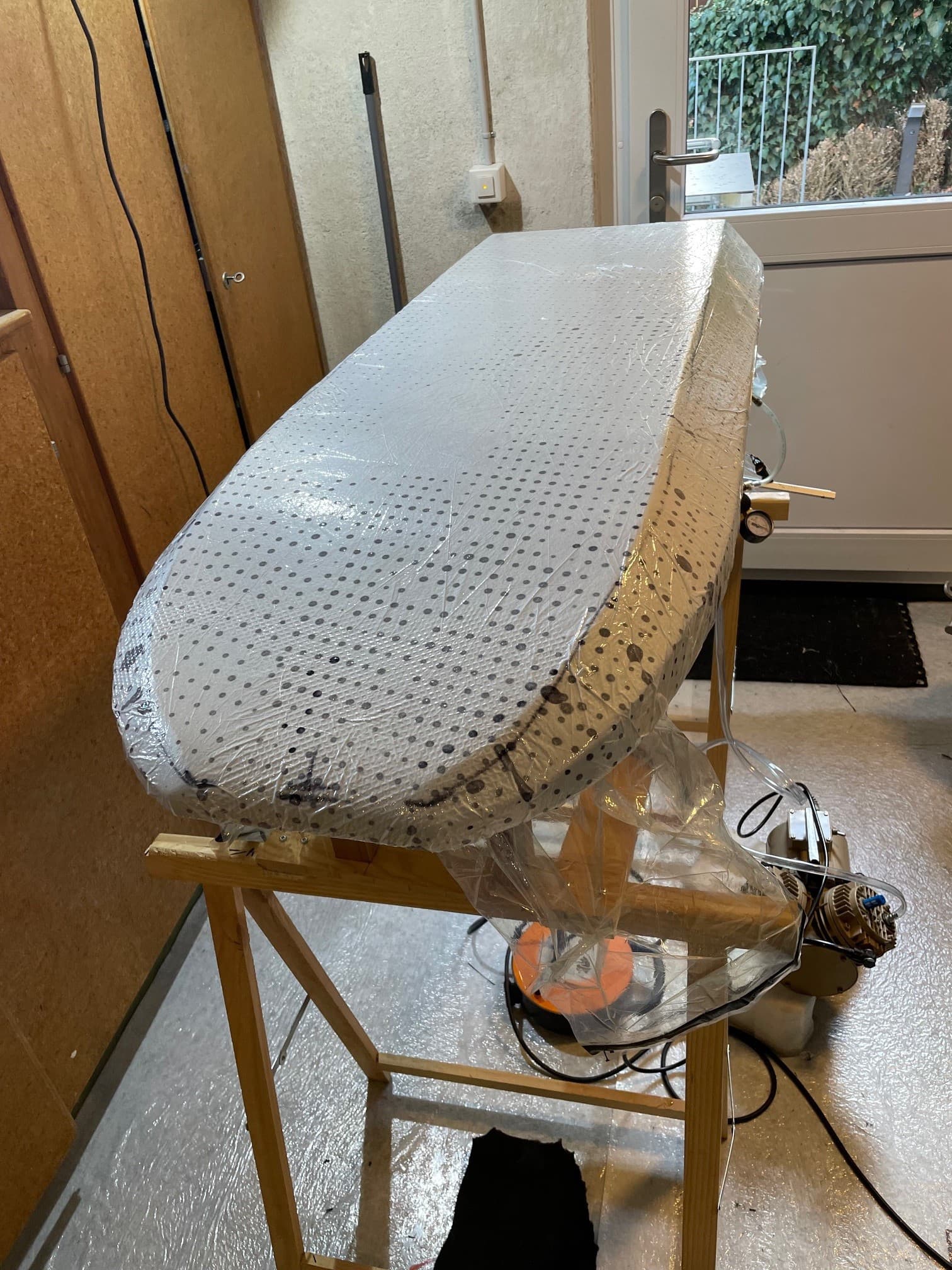
Each half shell was vacuum bagged (-0.6 to -0.8 bar) with peel ply. Be careful with heat (like heating blanket), pla with 15% infill will deform under pressure, if it gets above 50 degrees C.
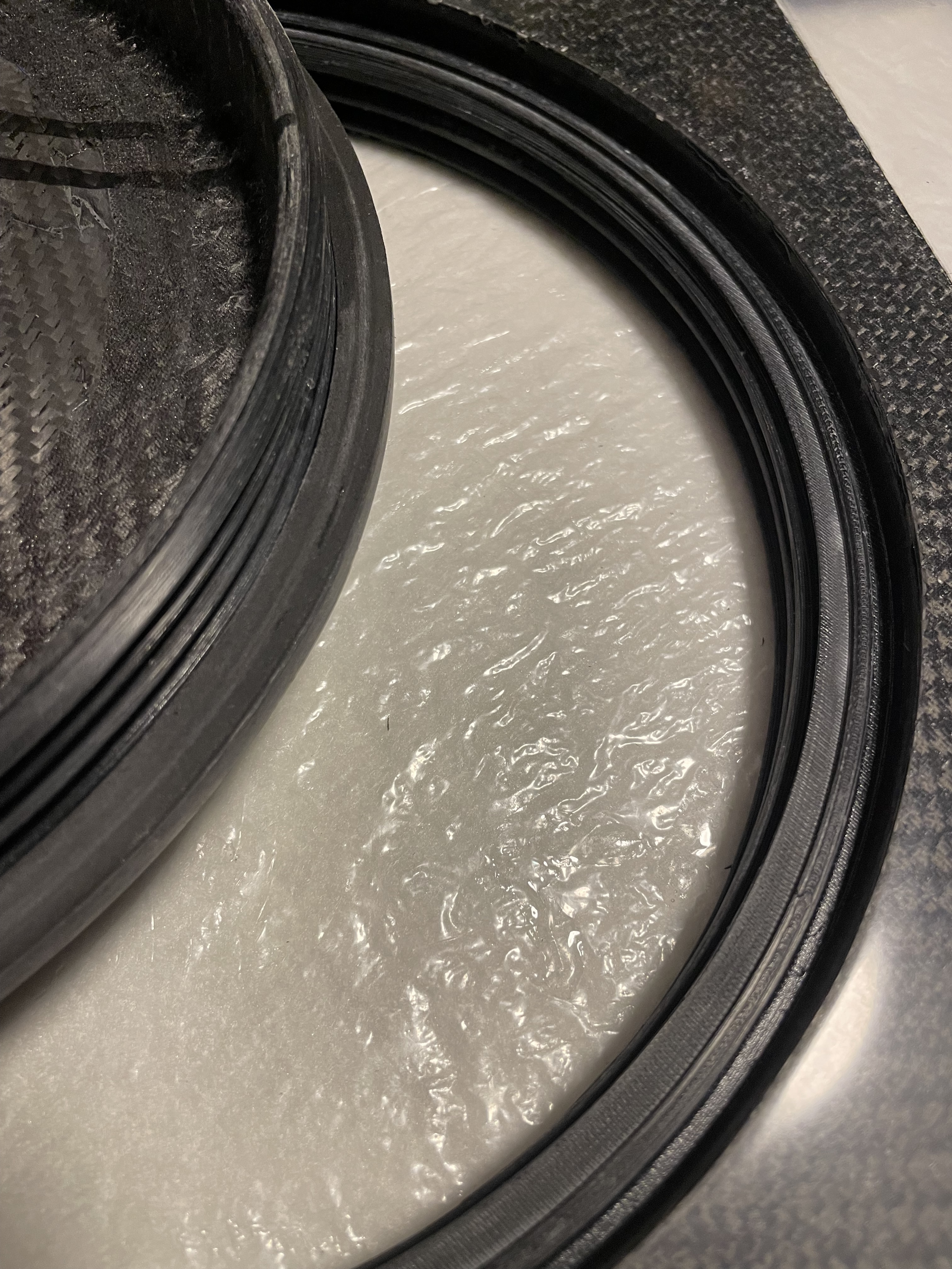
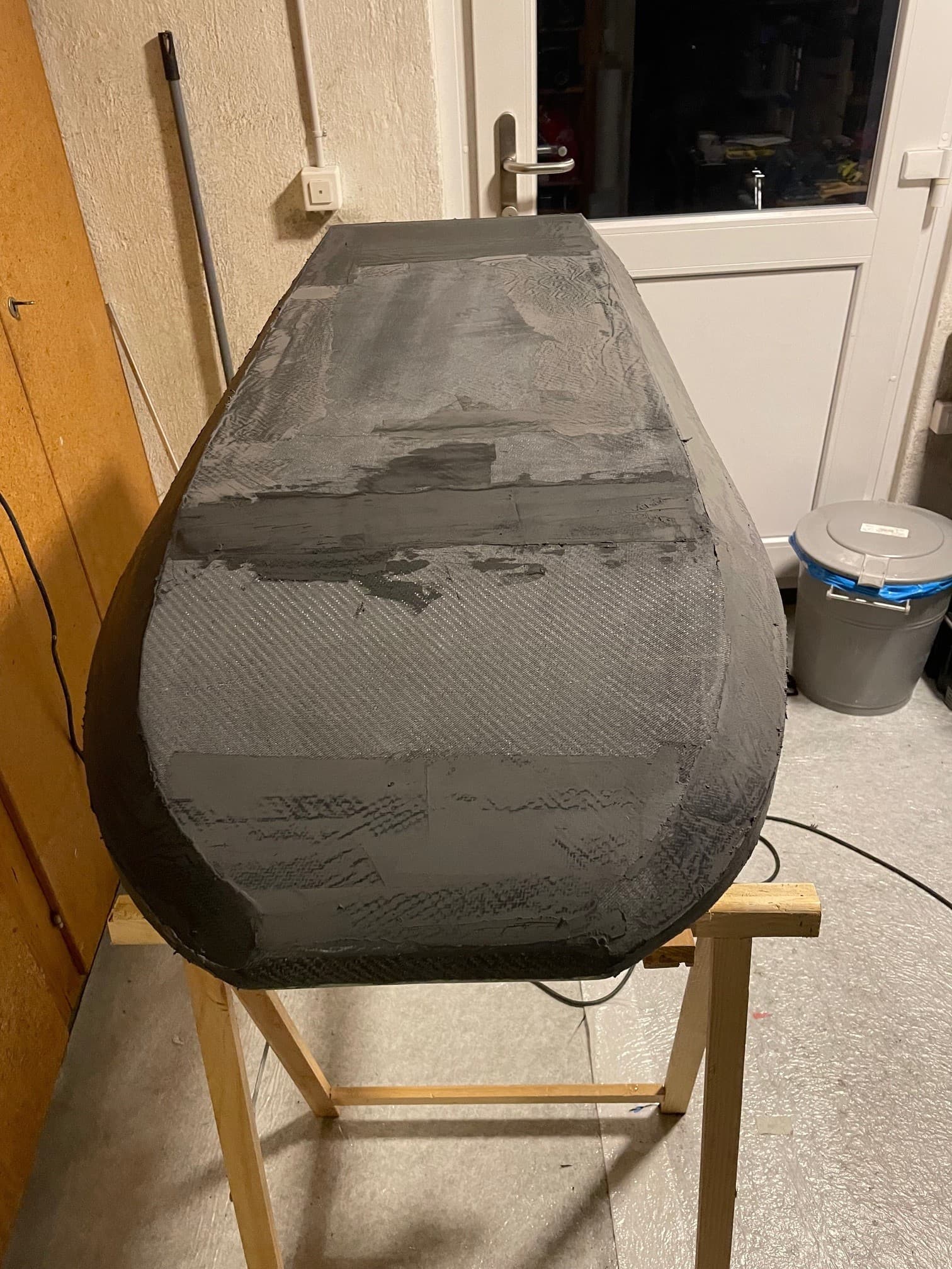
The two cured halves need to be trimmed until they fit into the mold again.
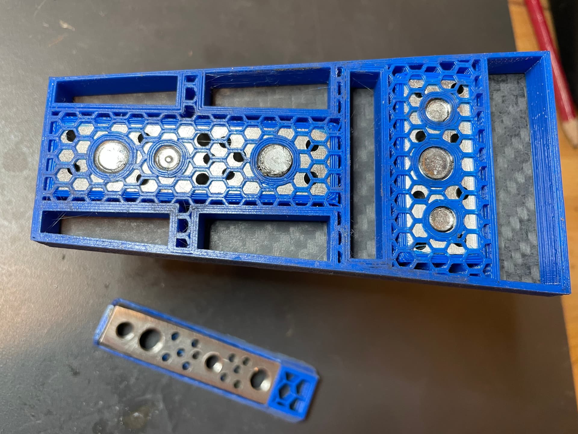
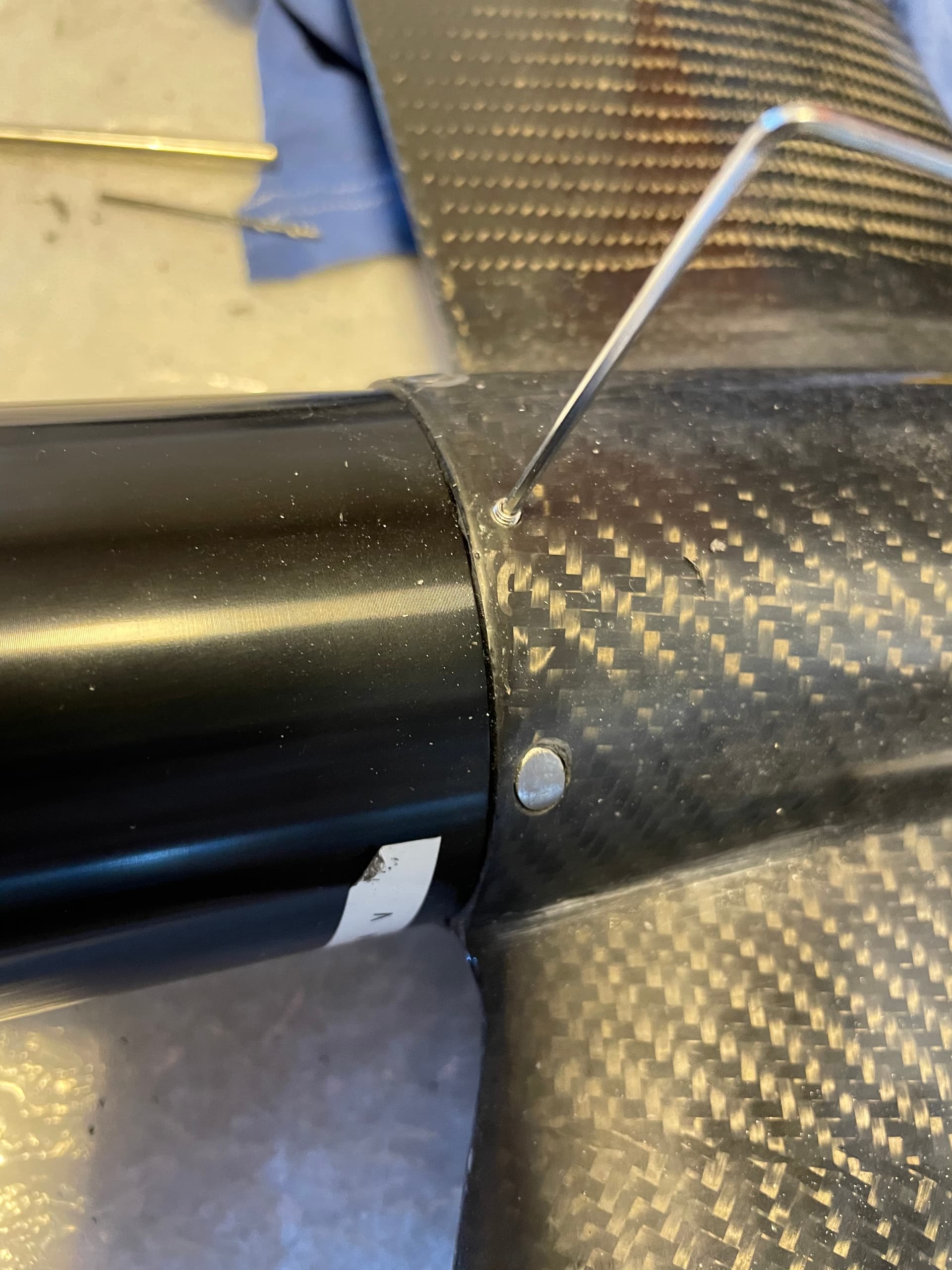
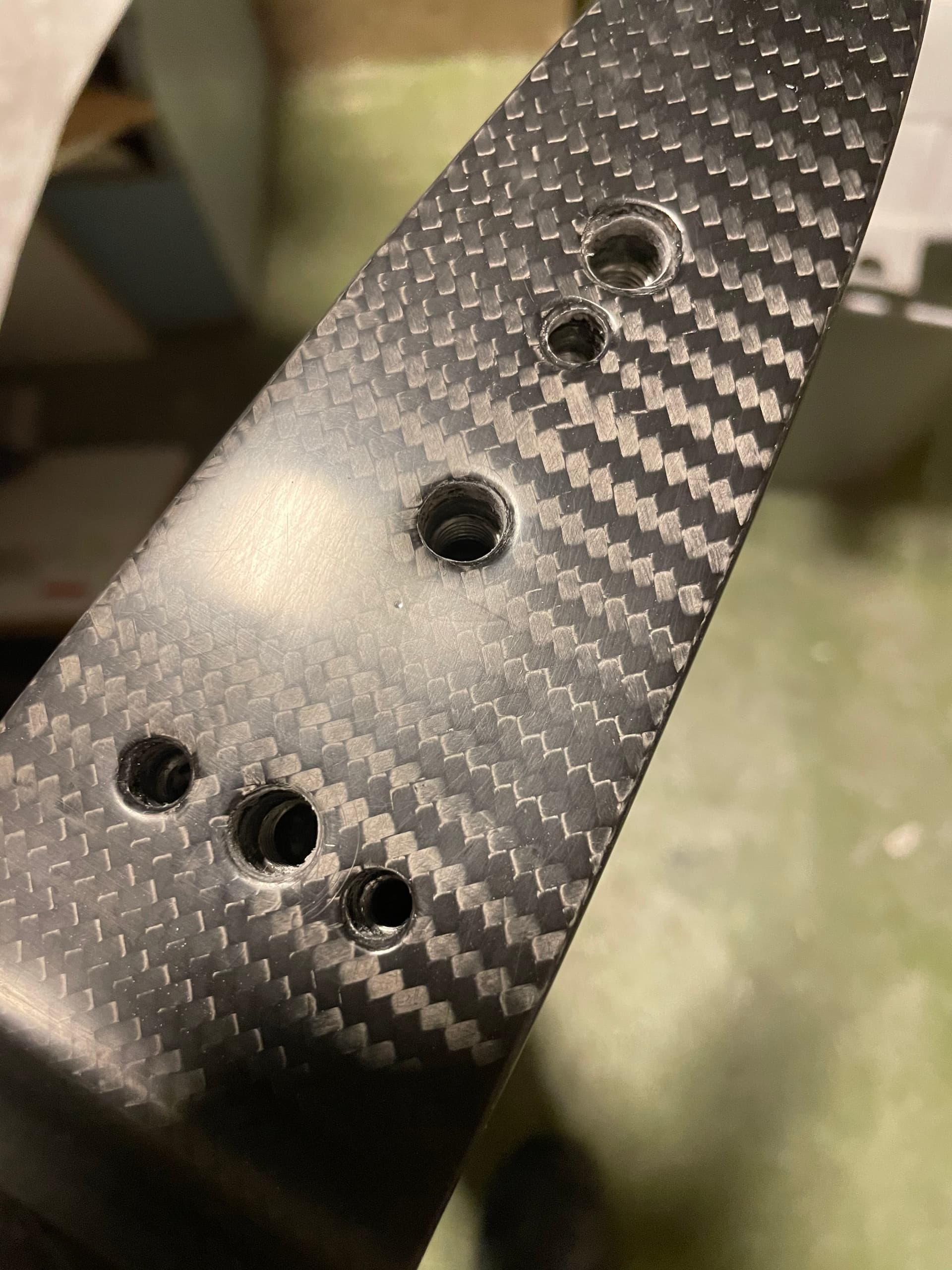
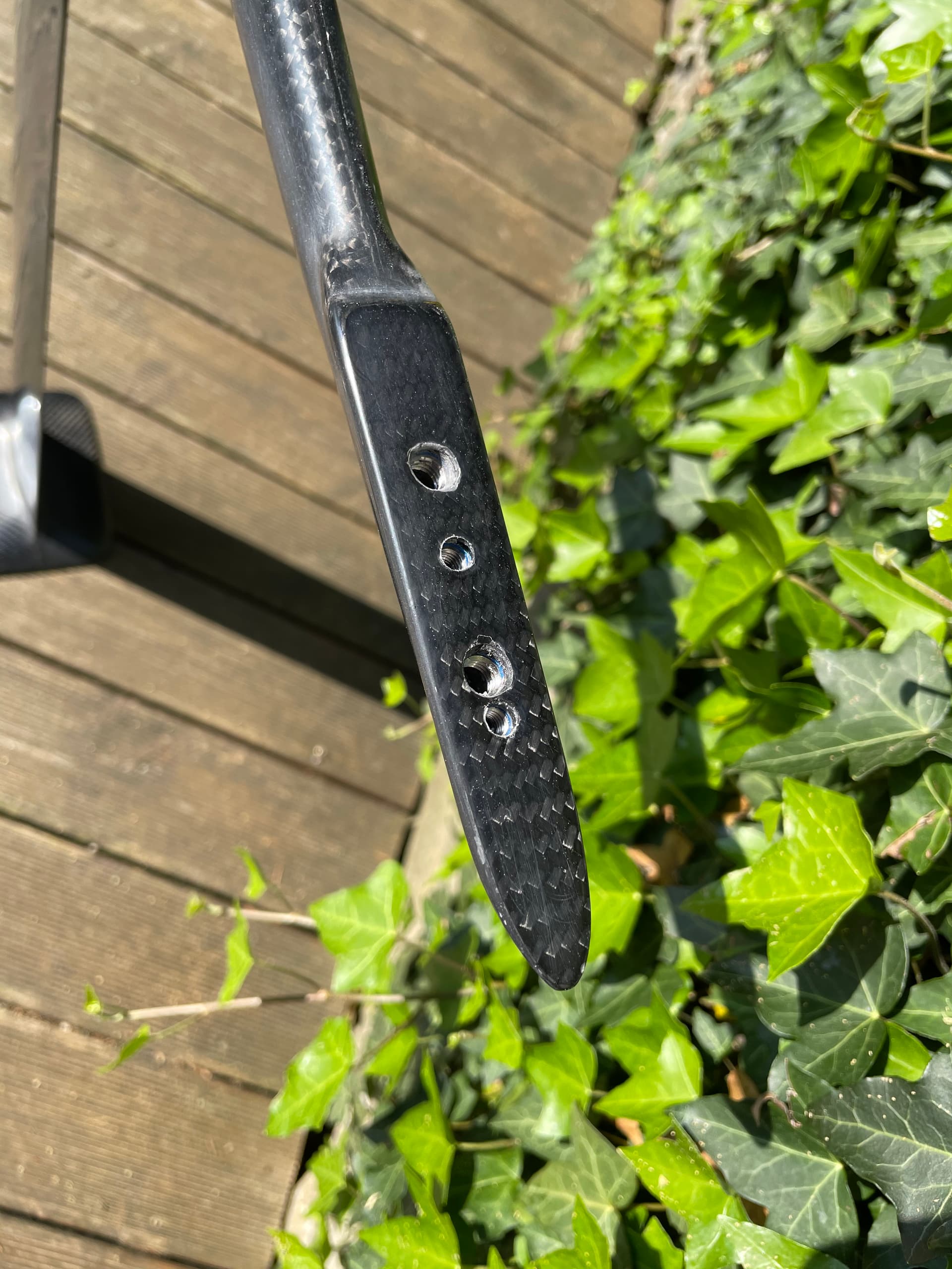
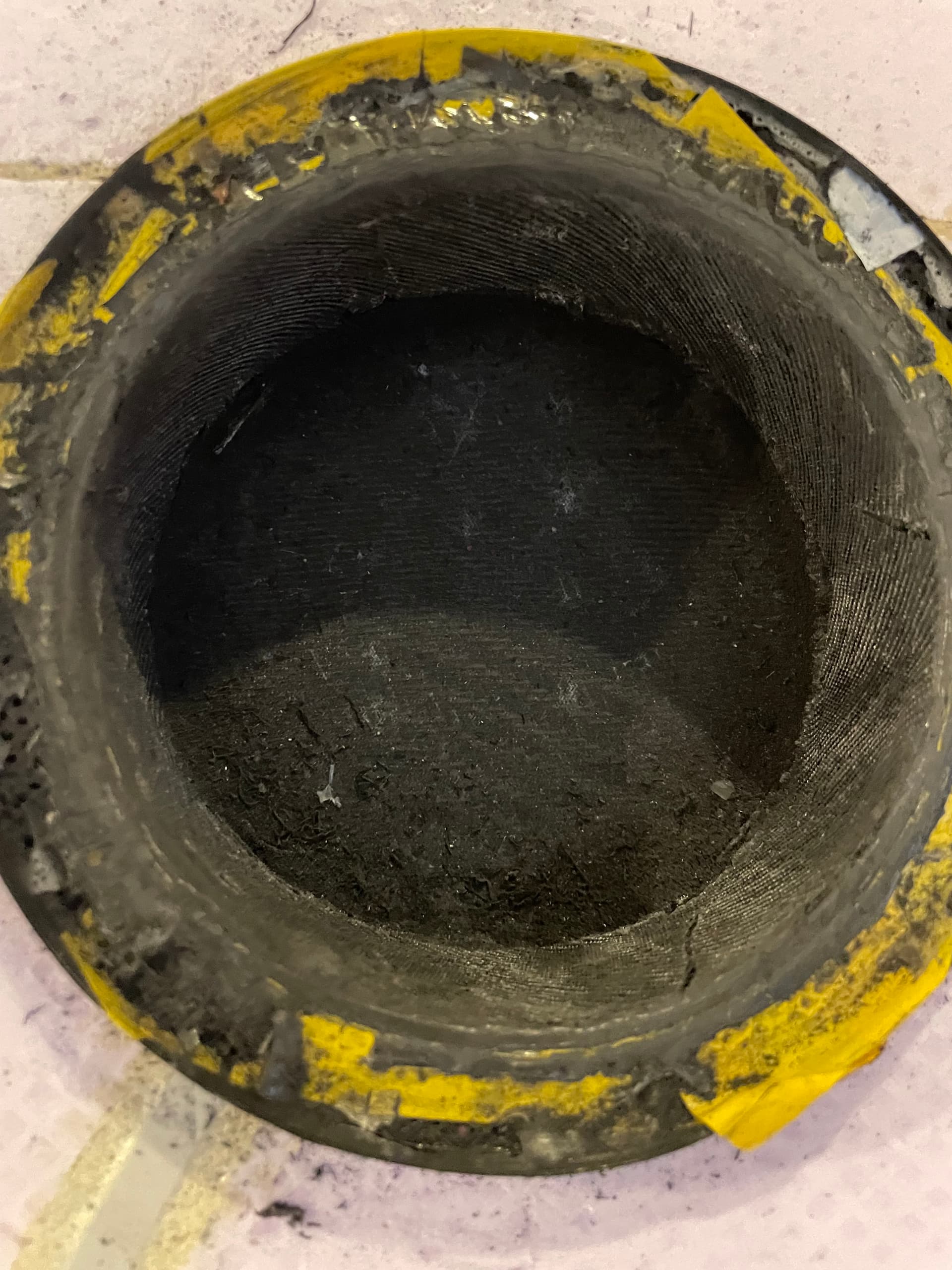
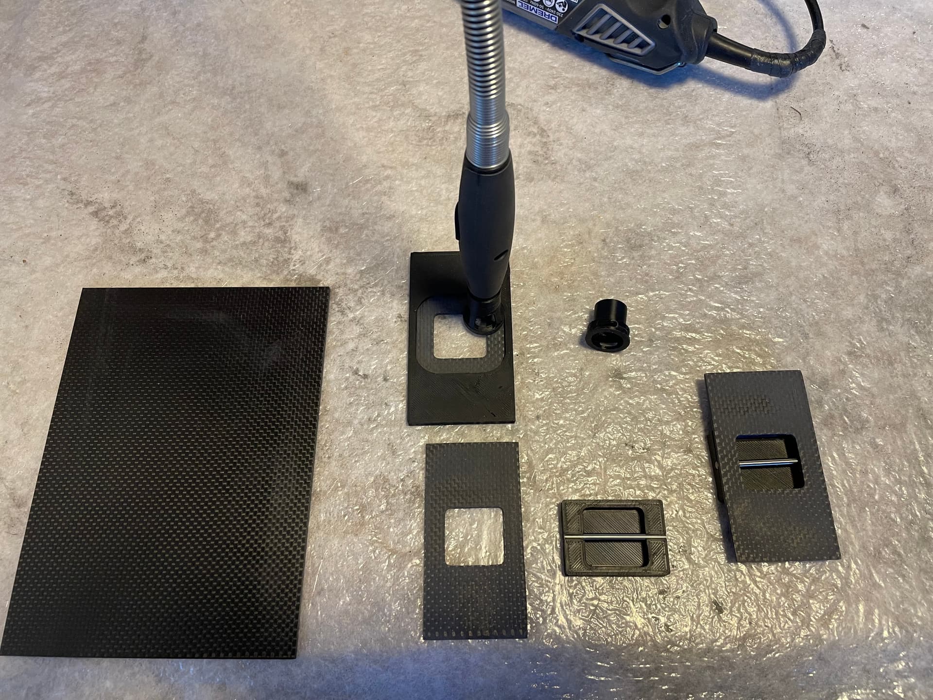
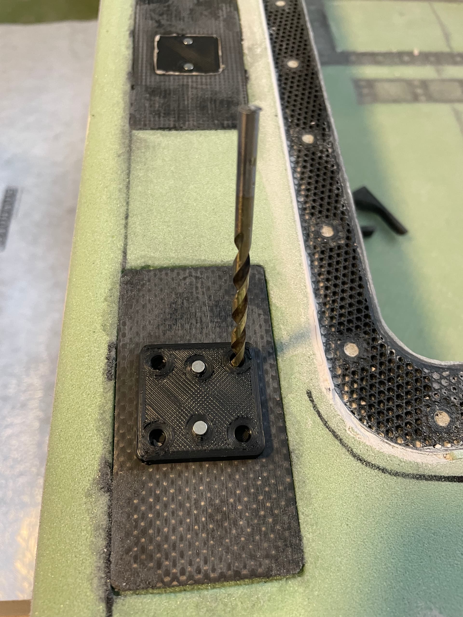
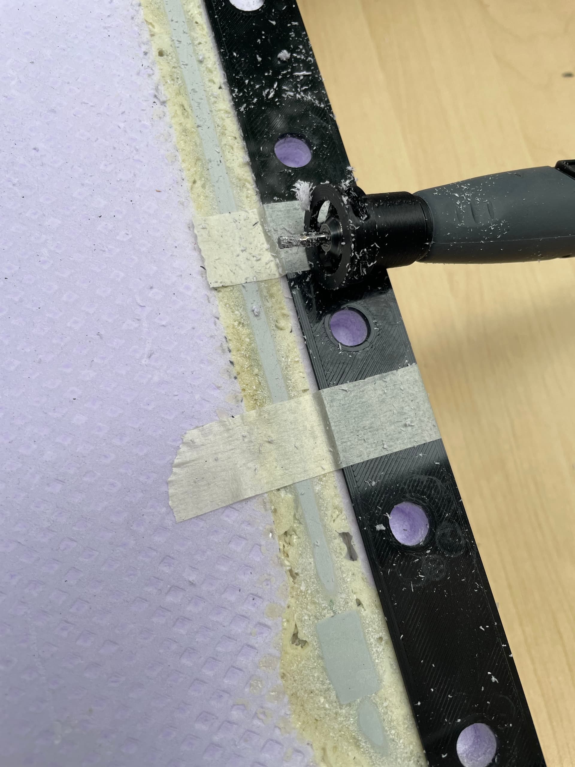
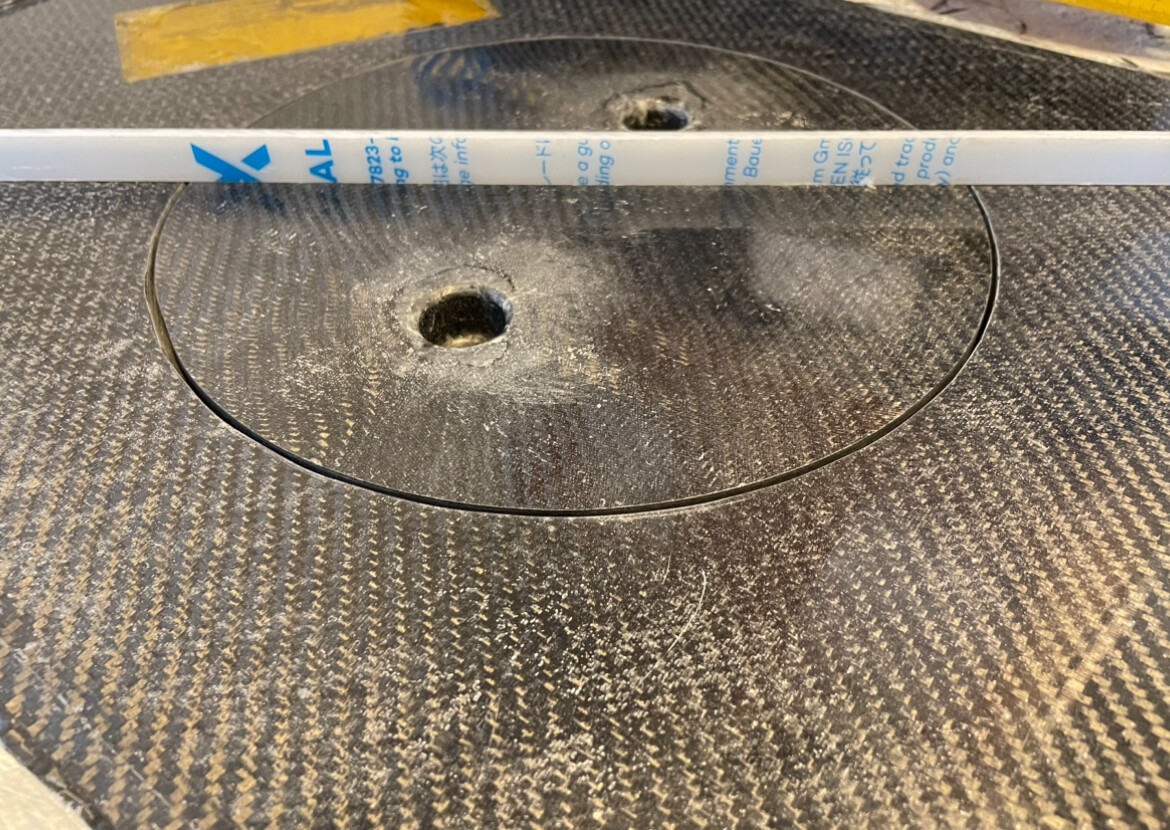
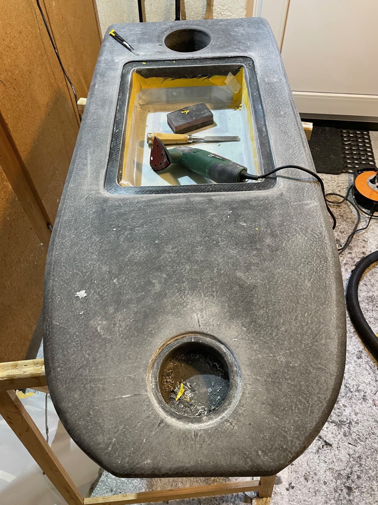
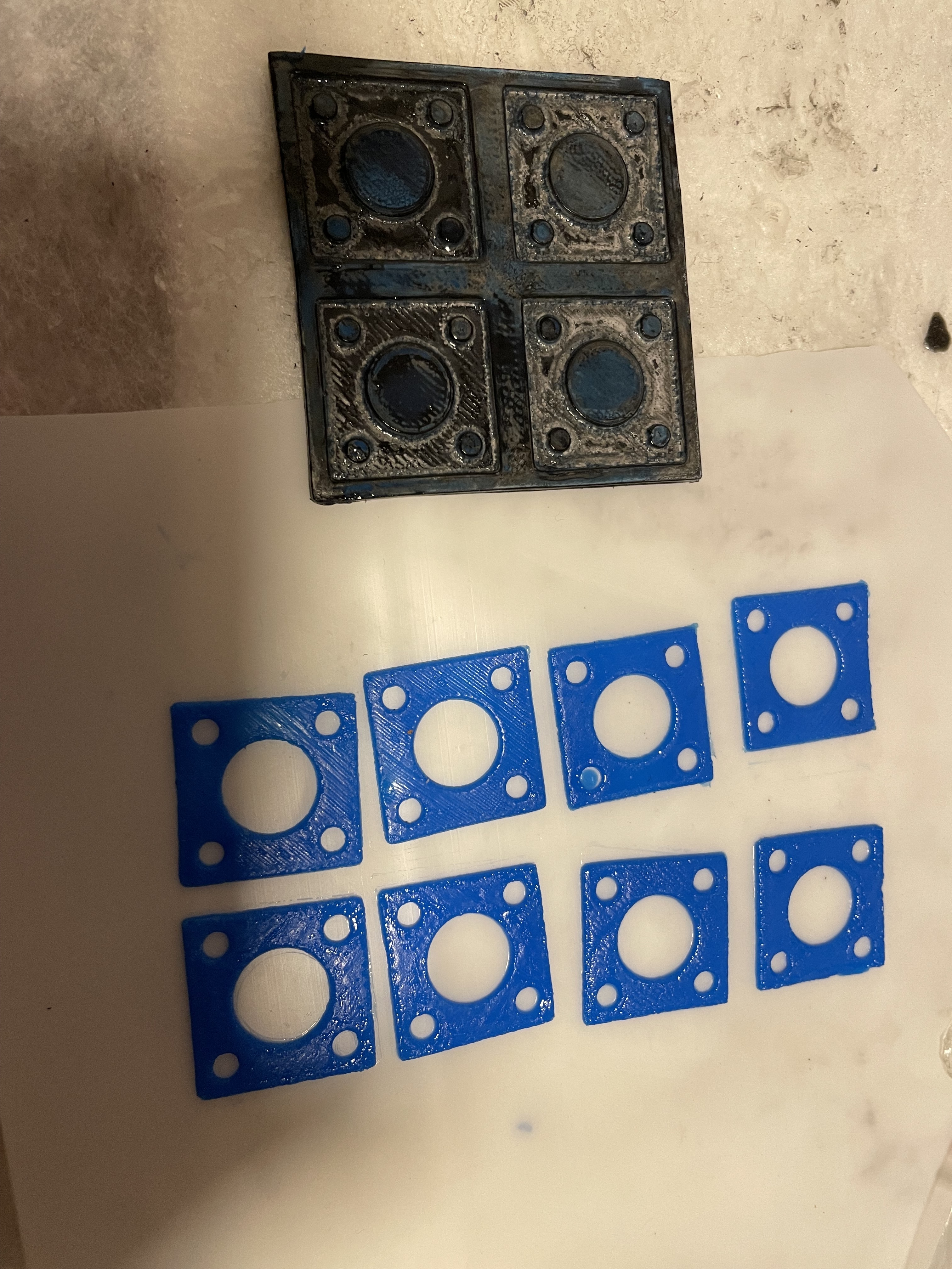
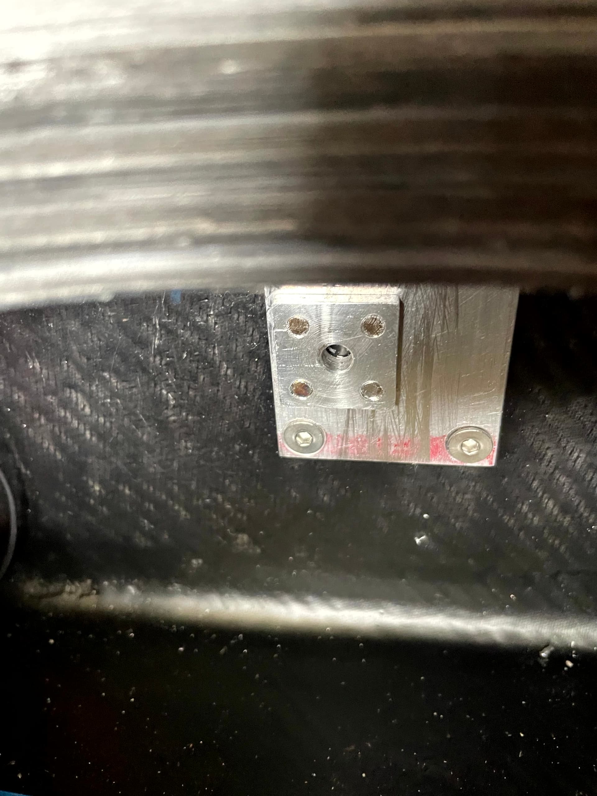
Last step is to fill the mold with a mixture of cfk flakes and thickened epoxy with micro balloons and thickener. Trimm again. I made a 3d printed drill jig to drill the holes.
printed in esun pla+, 15% infill gyroid
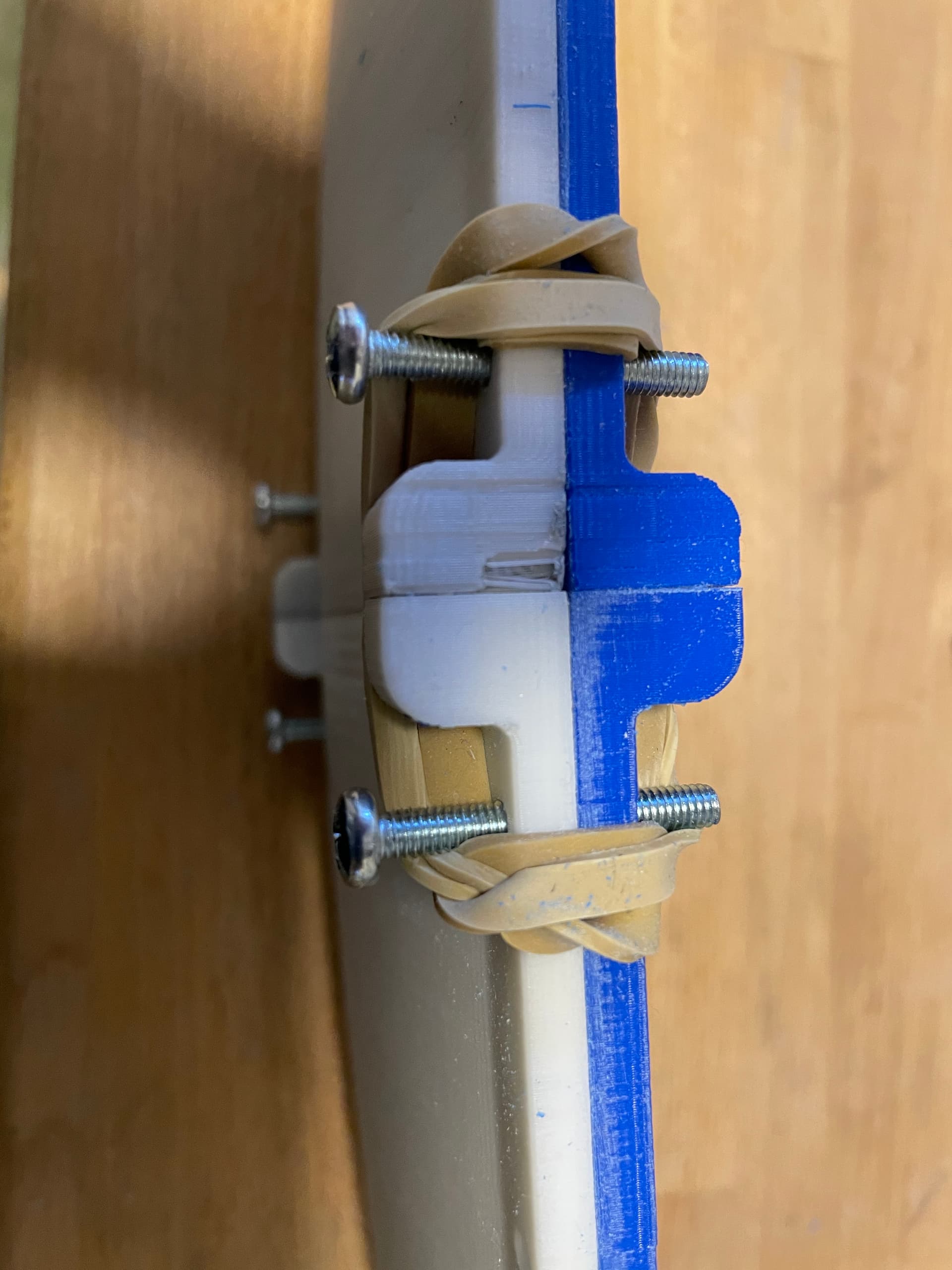
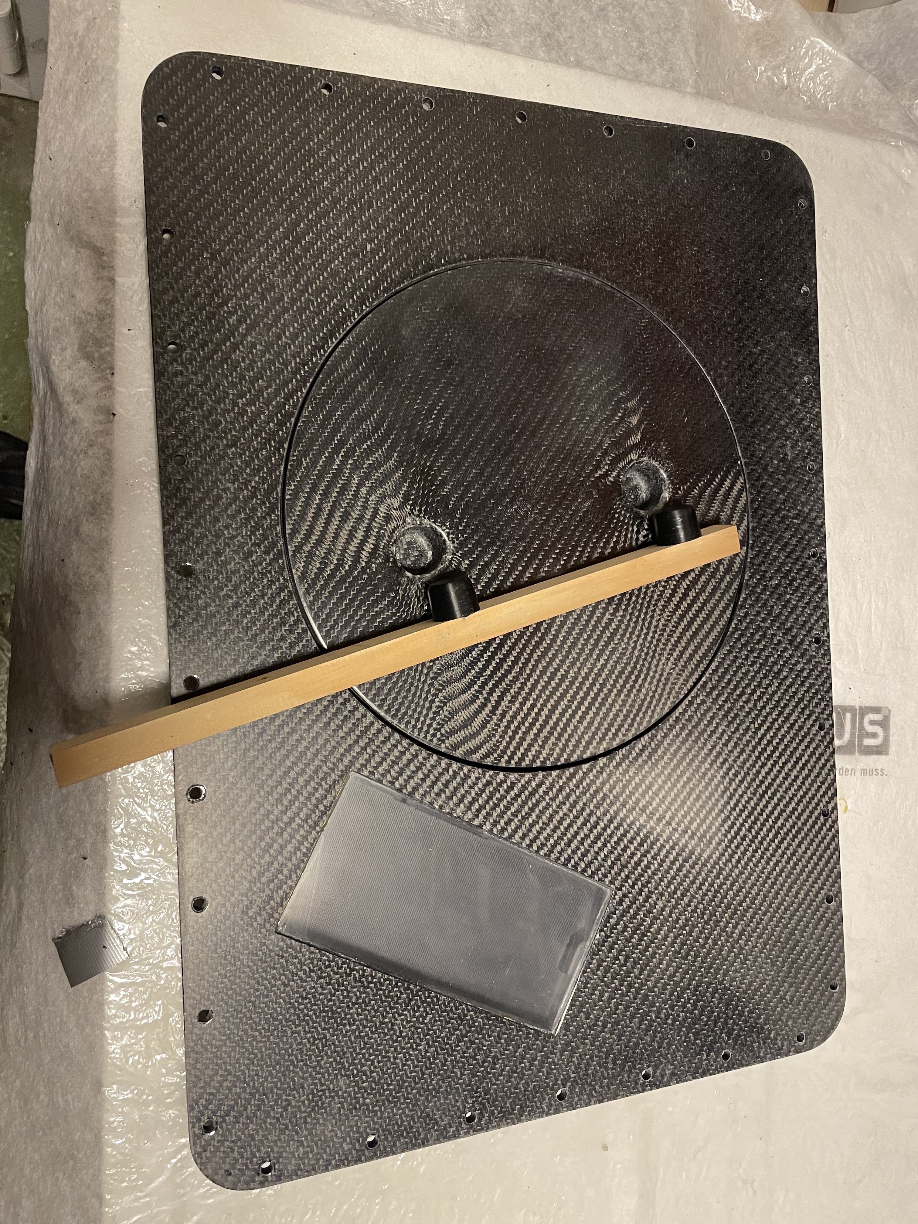
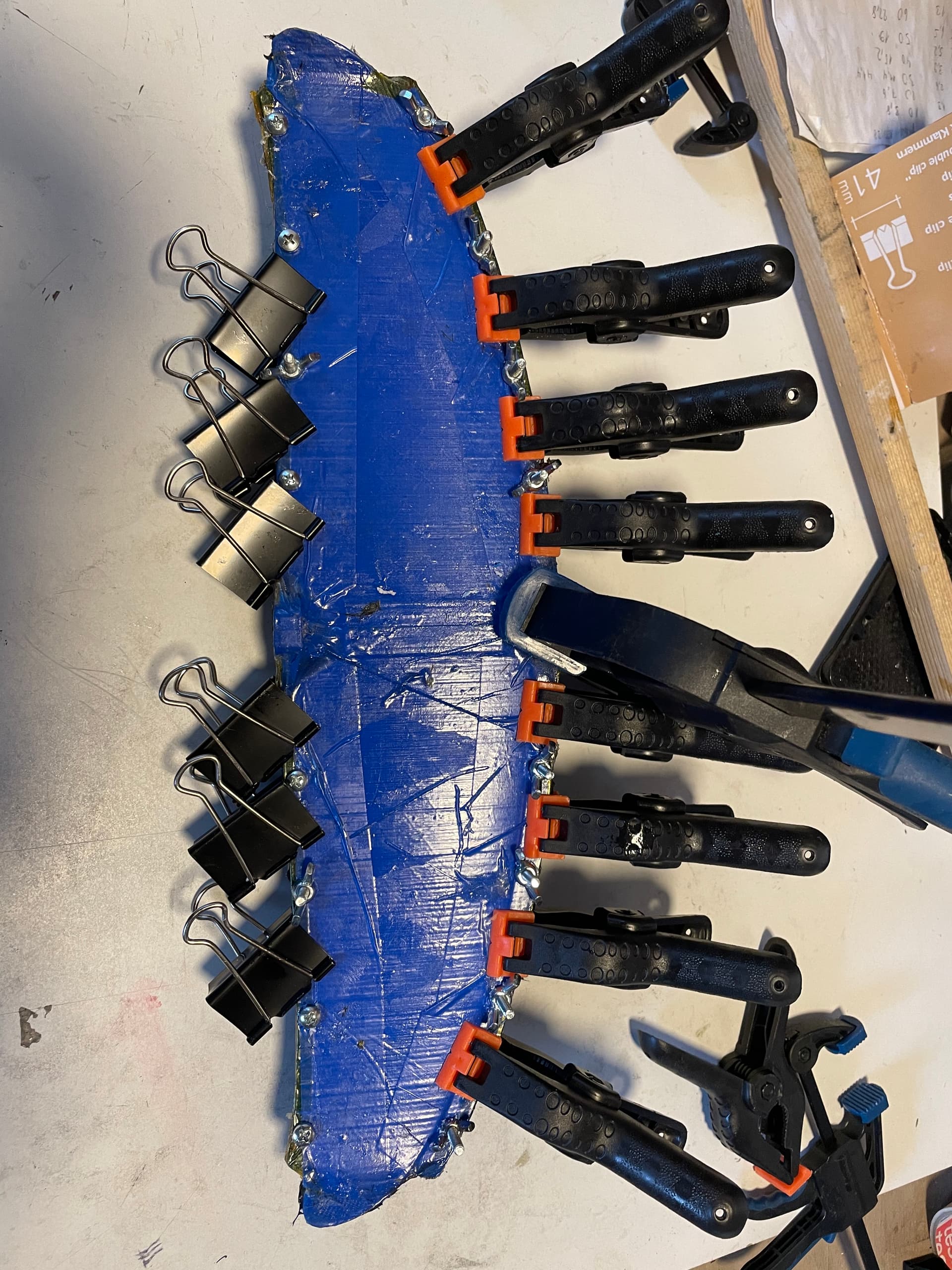
glued the two halves with 2k epoxy glue
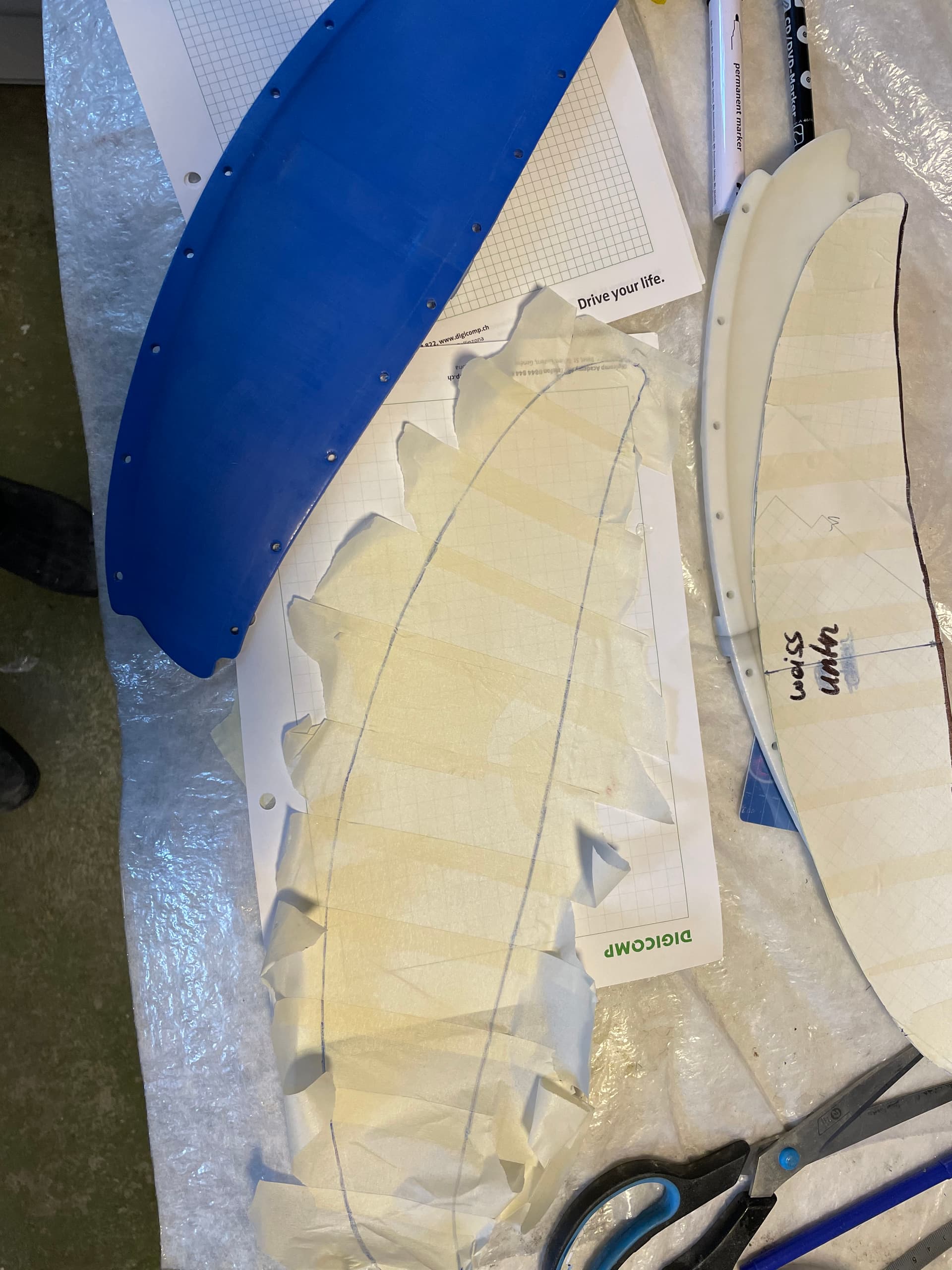
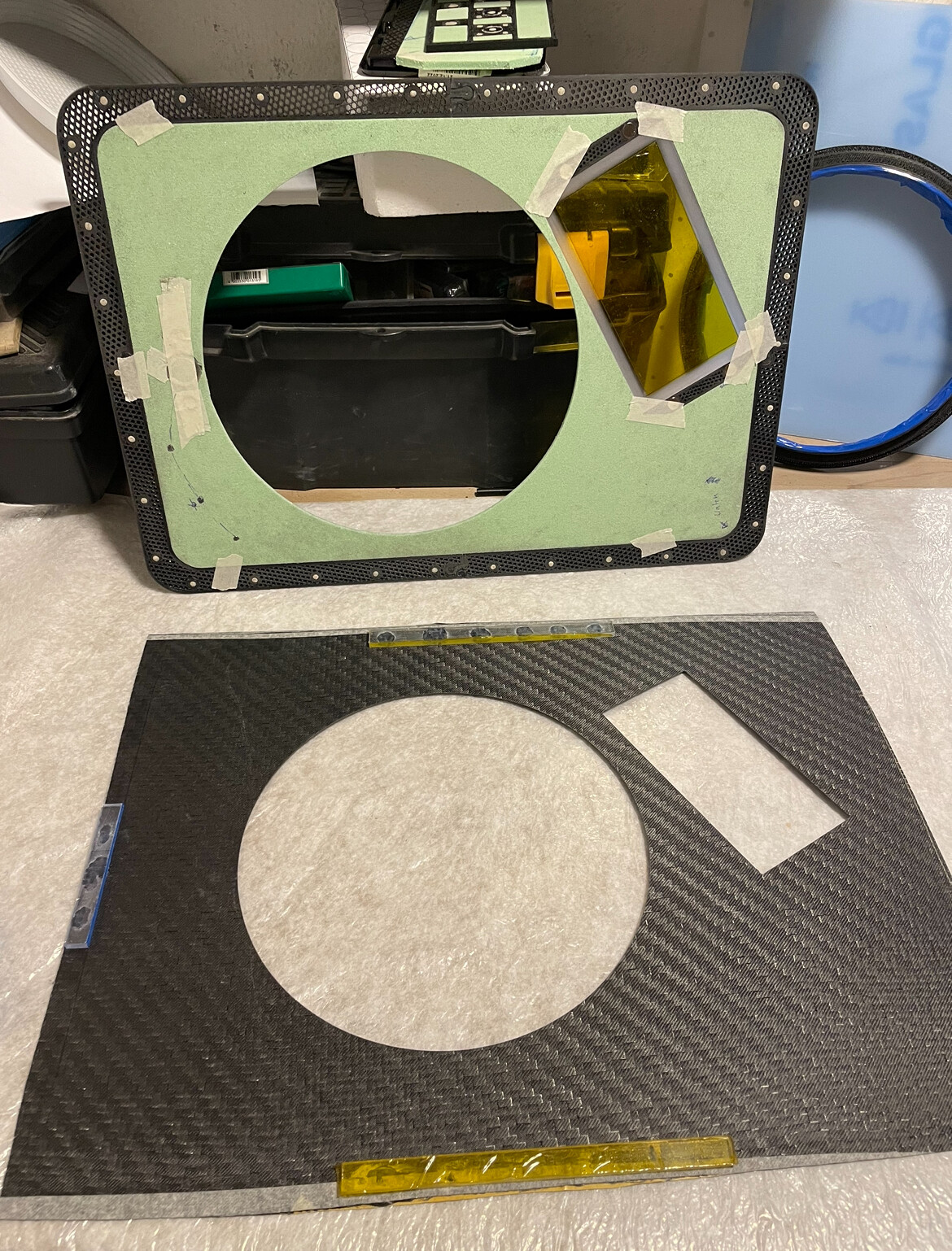
Templates from masking tape

a little bit of spray glue helps to keep the cfk edges nice
200g/m2 twill and some layers of 300g/m2 biax


reserved for link to thingiverse:
link to another backwing I designed: Hydrofoil rear wing mould by dfi - Thingiverse

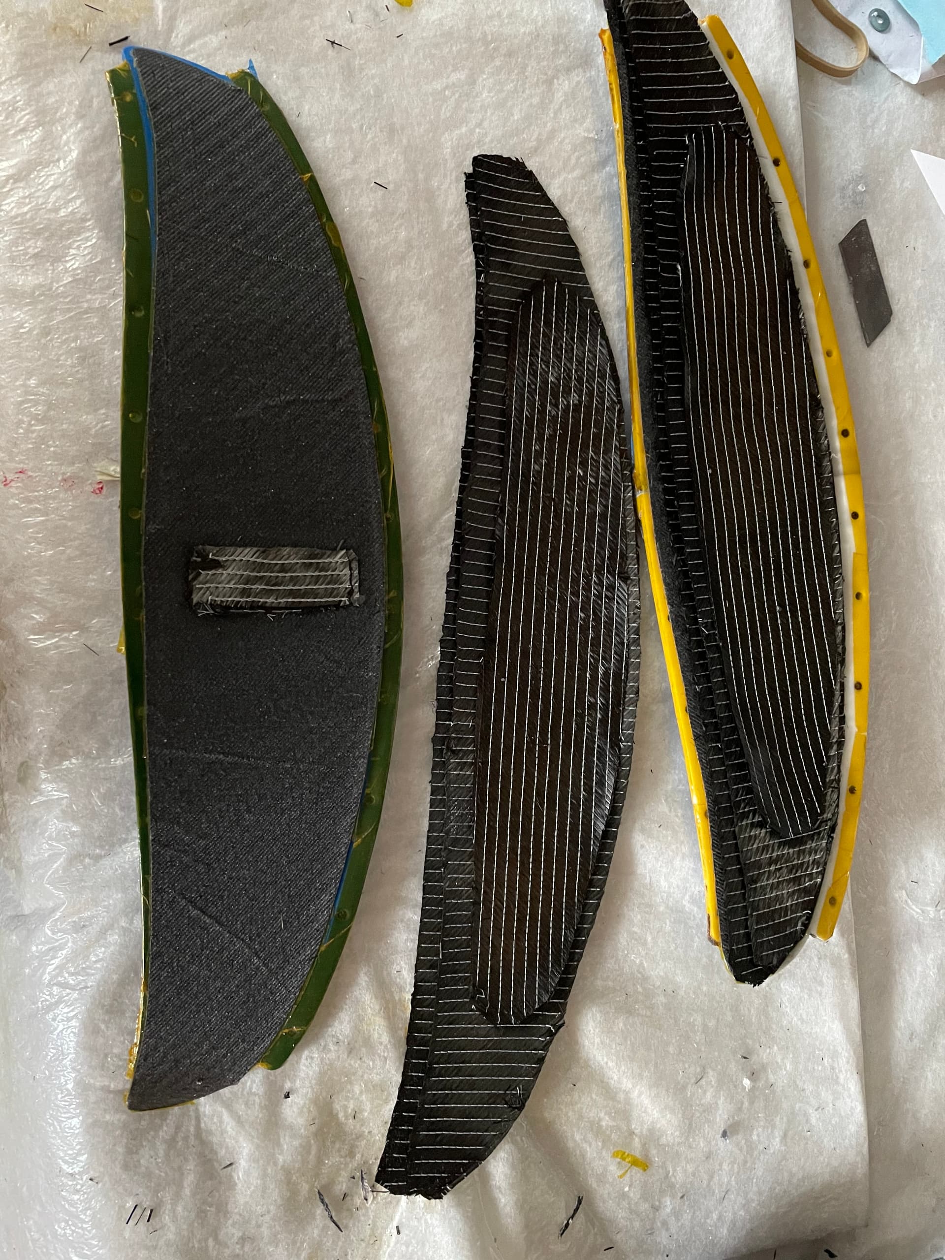
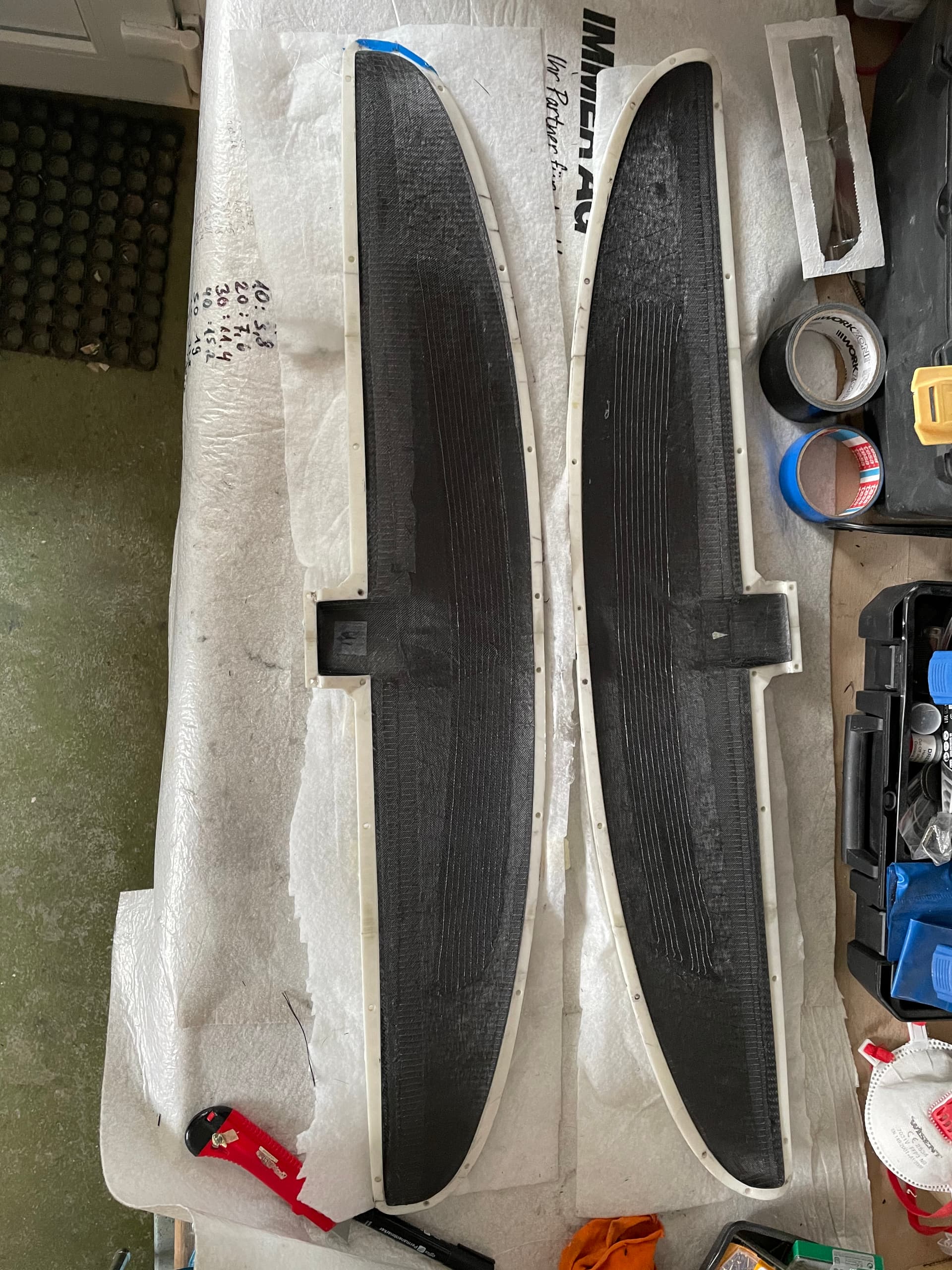
backwing collection:
from top: 320cm2, 280cm2, 220cm2
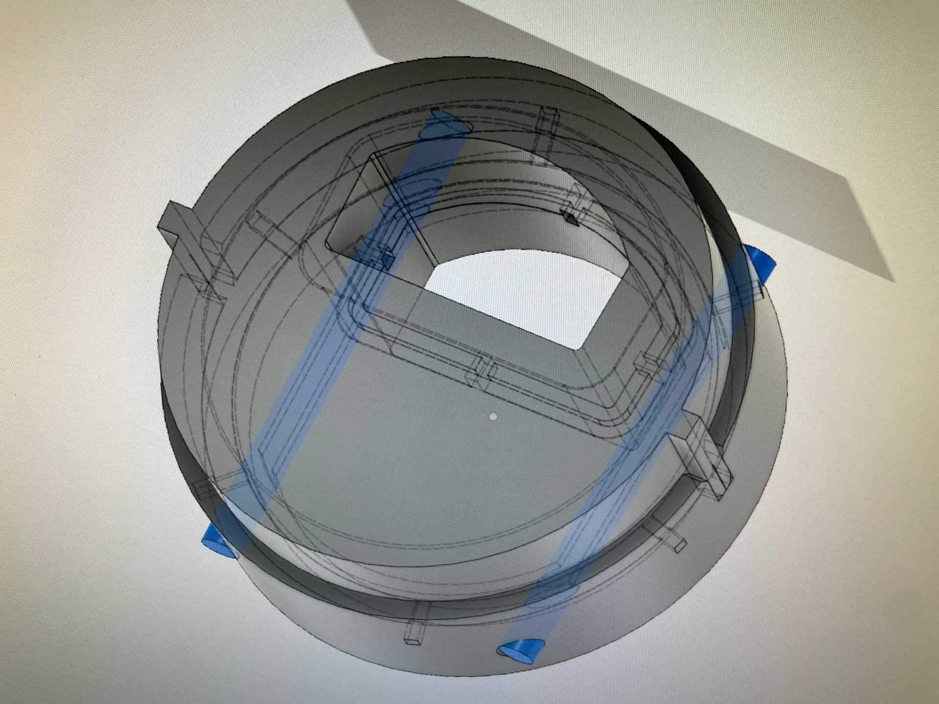
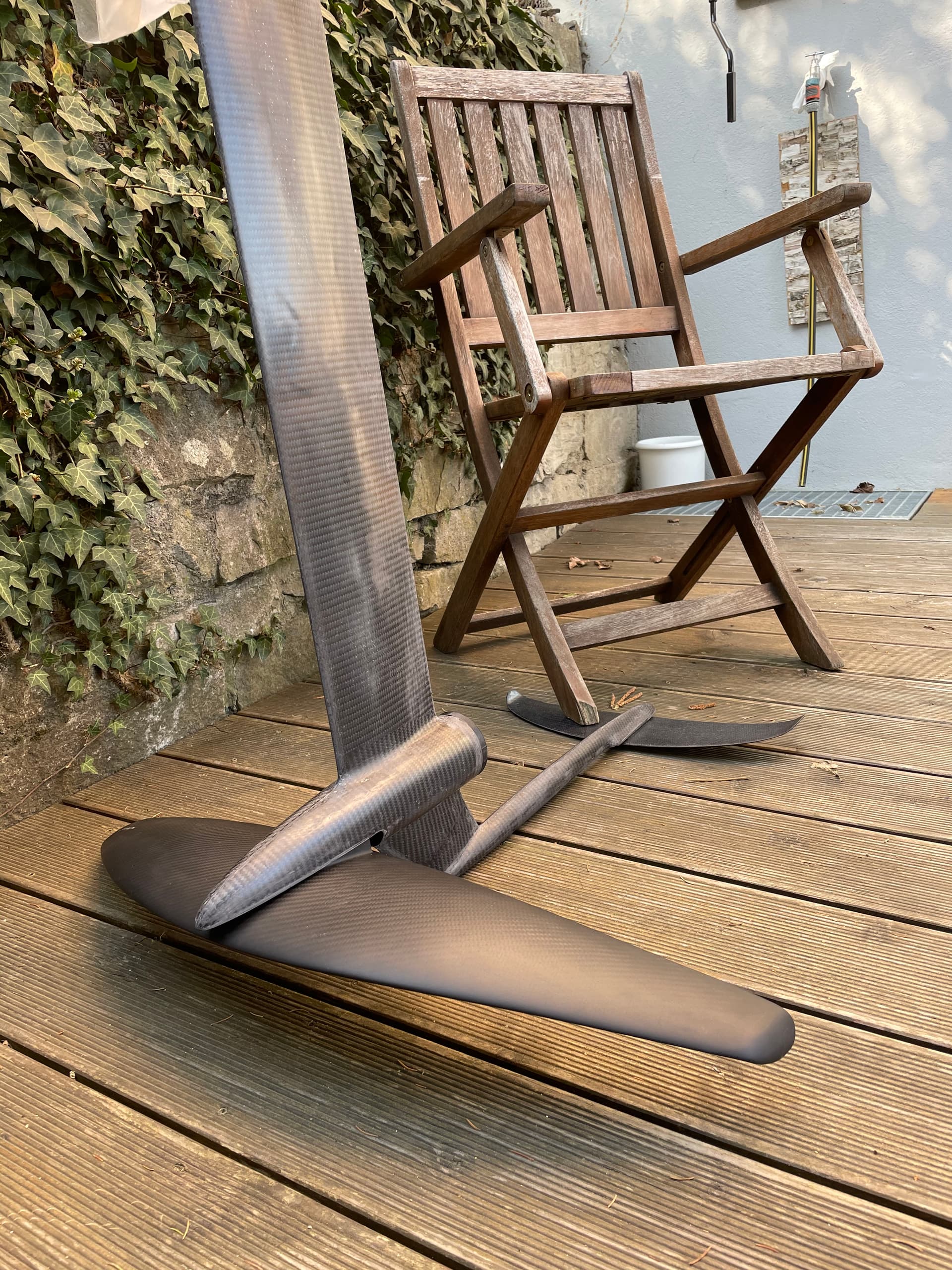
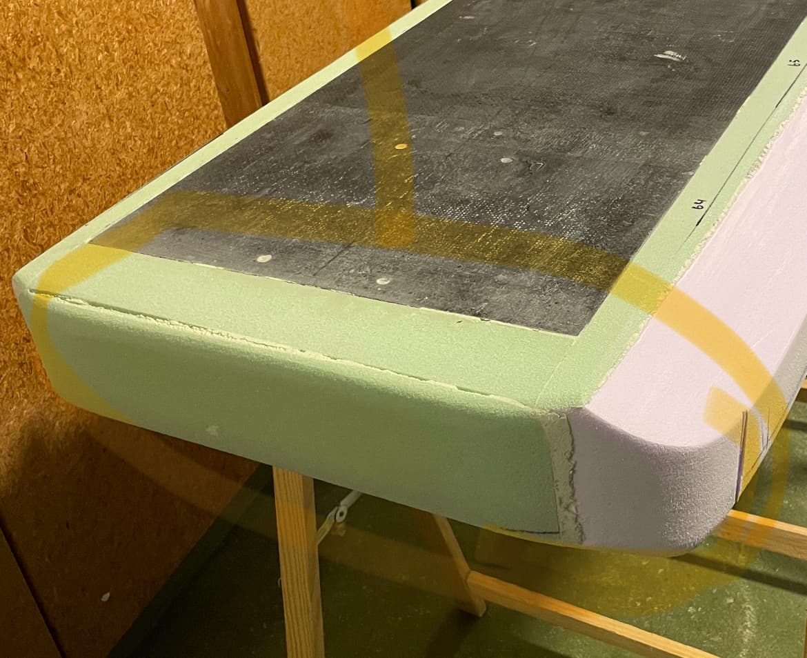
Front wing:
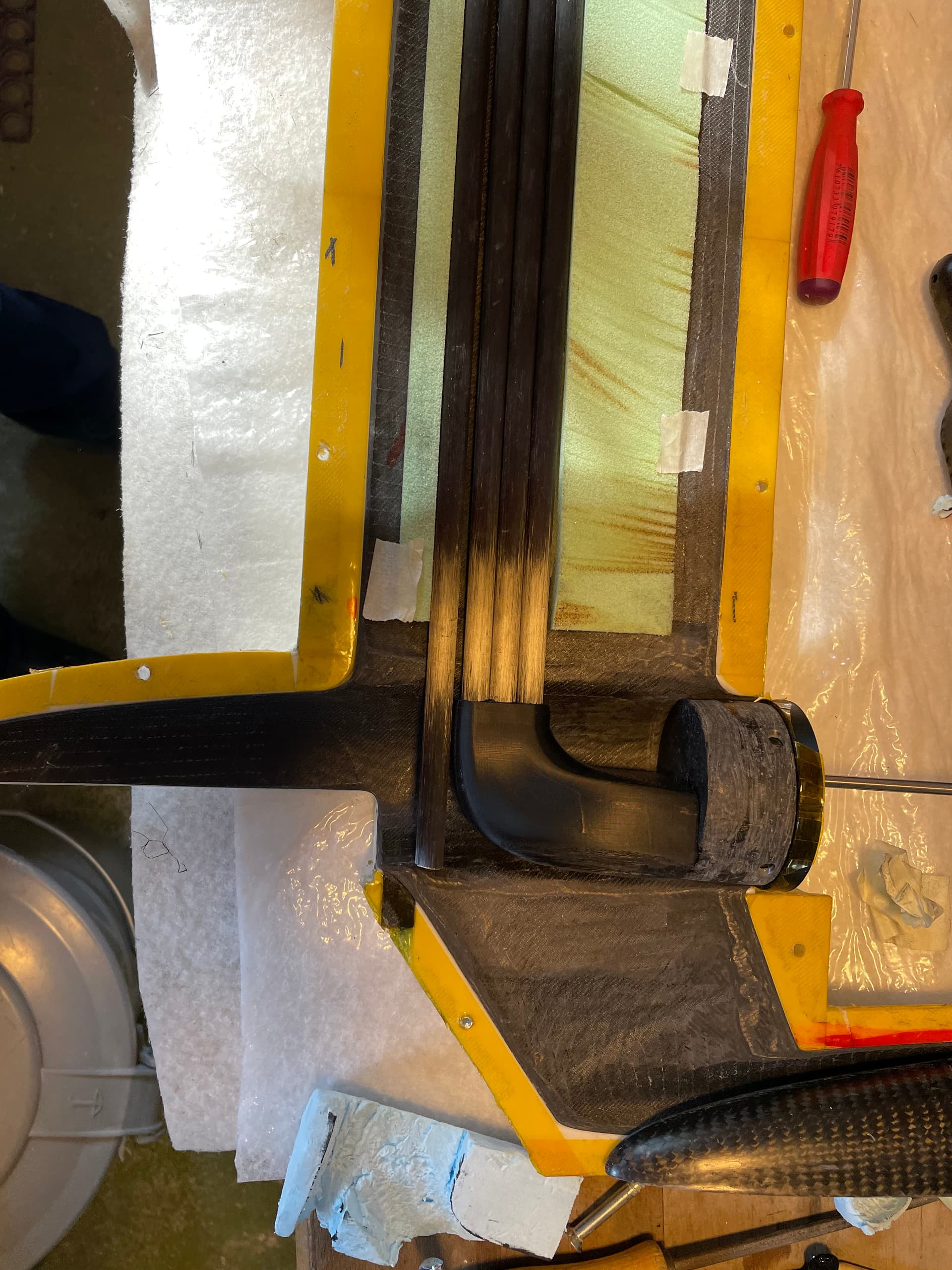
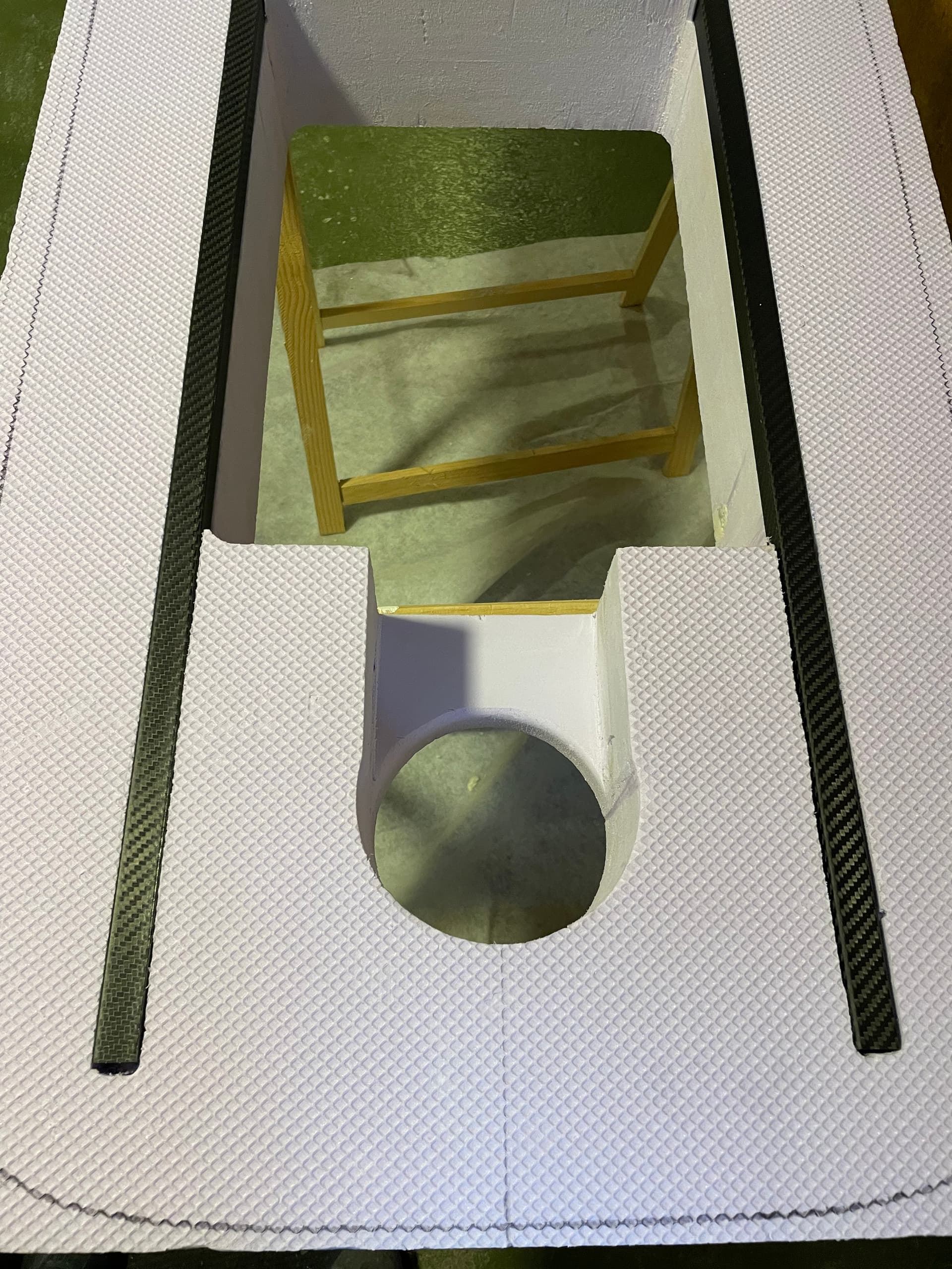
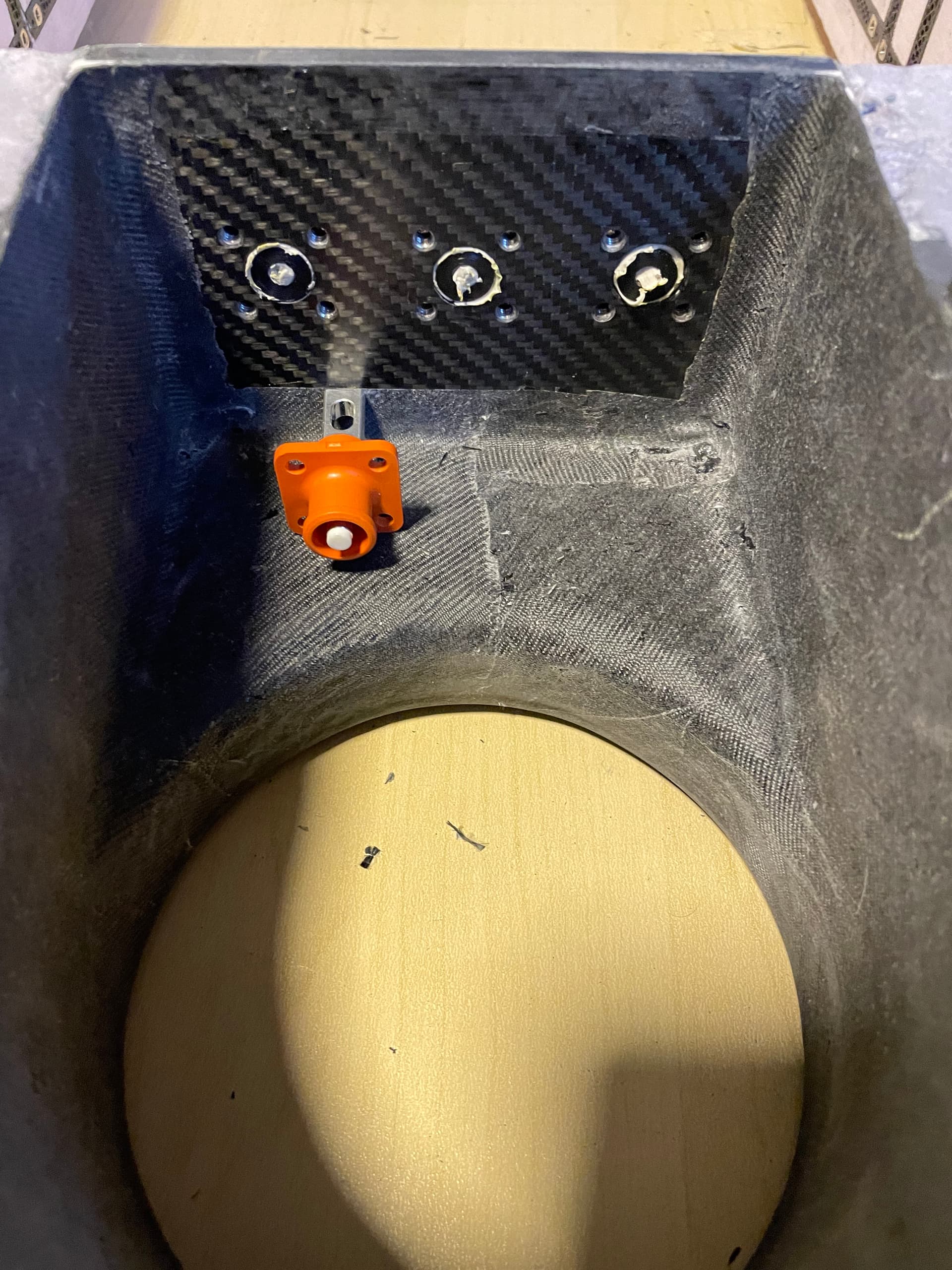
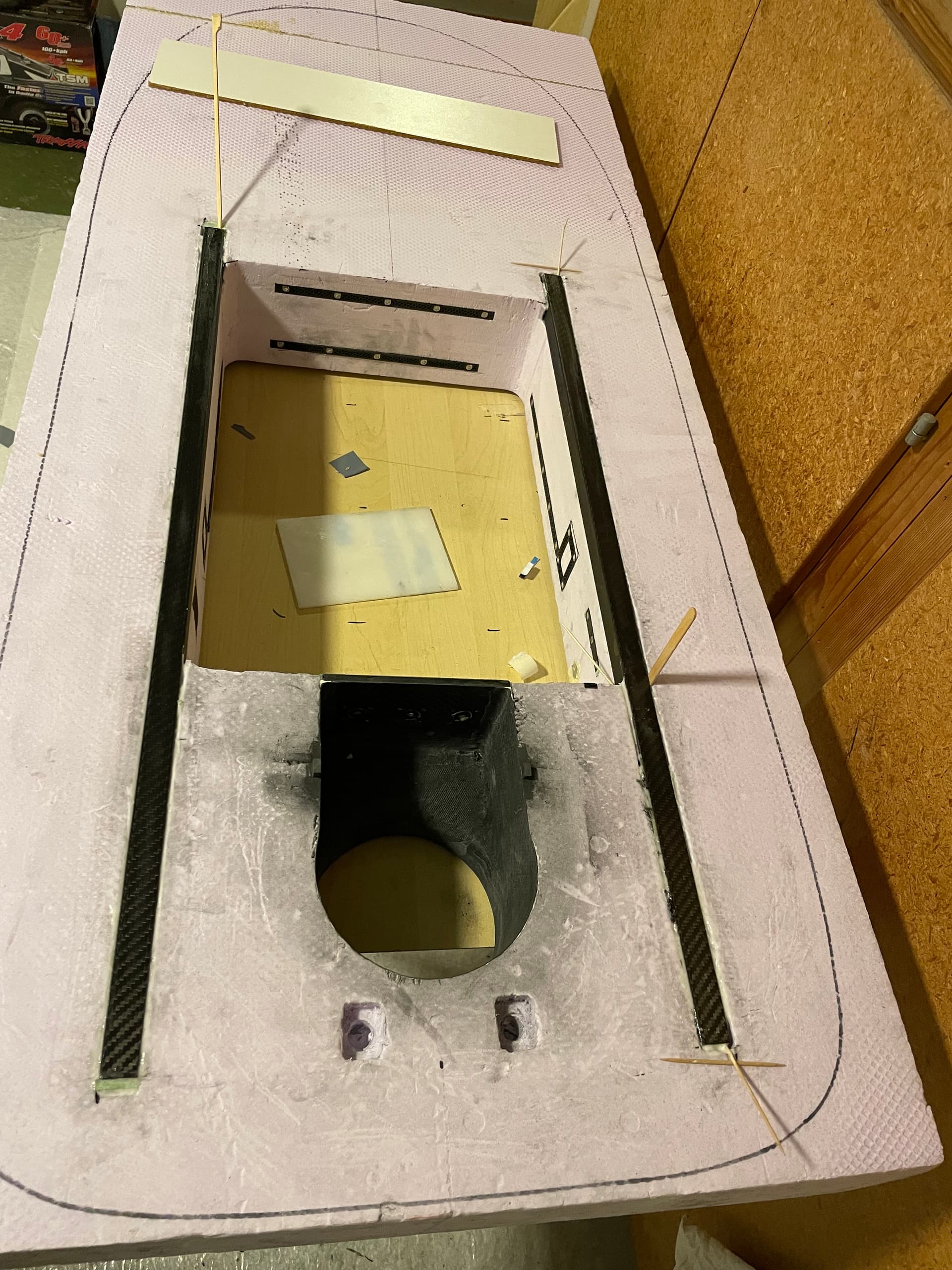
Front wing was built the same way but with a strut from cfk covered balsa.
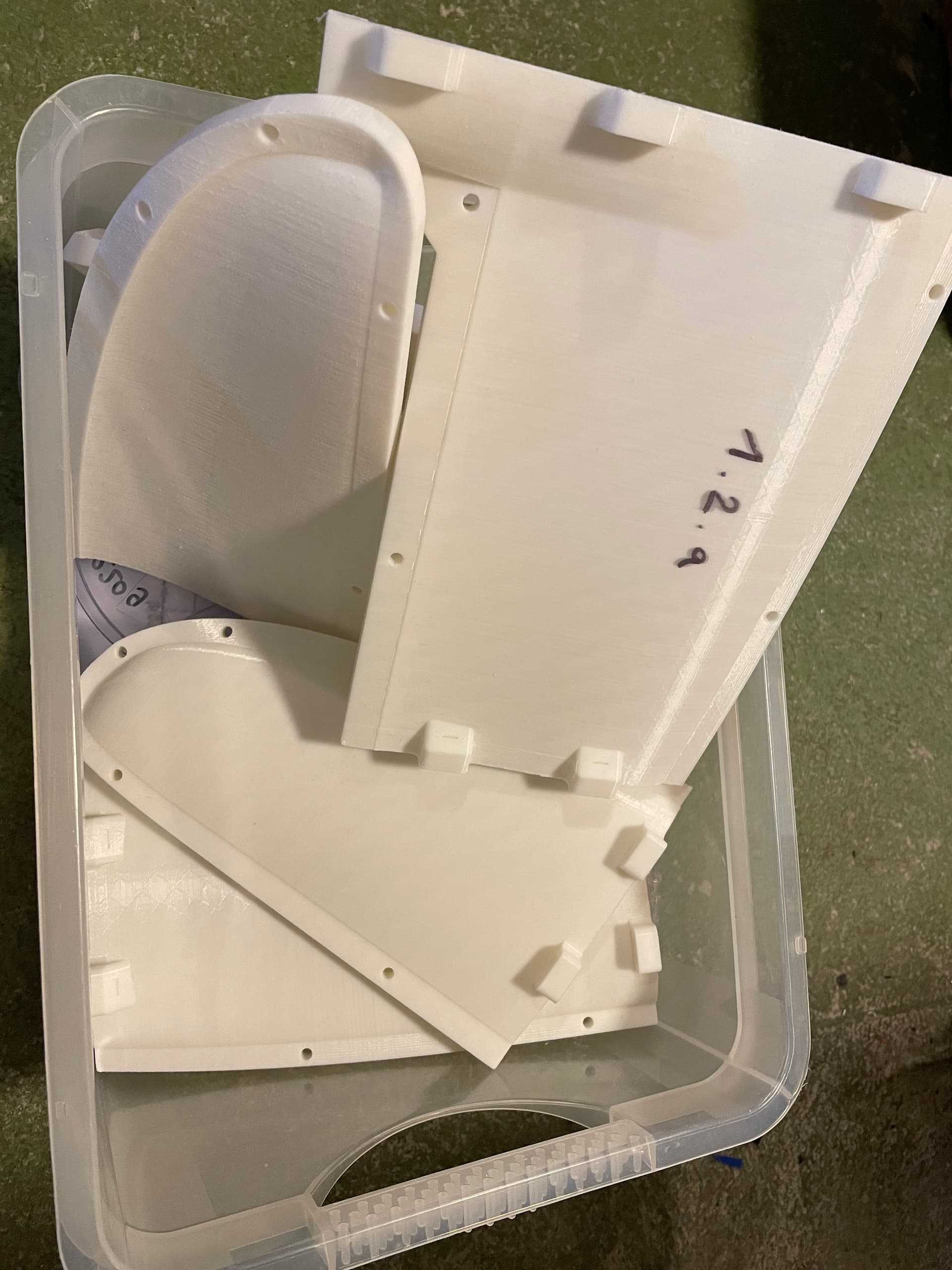
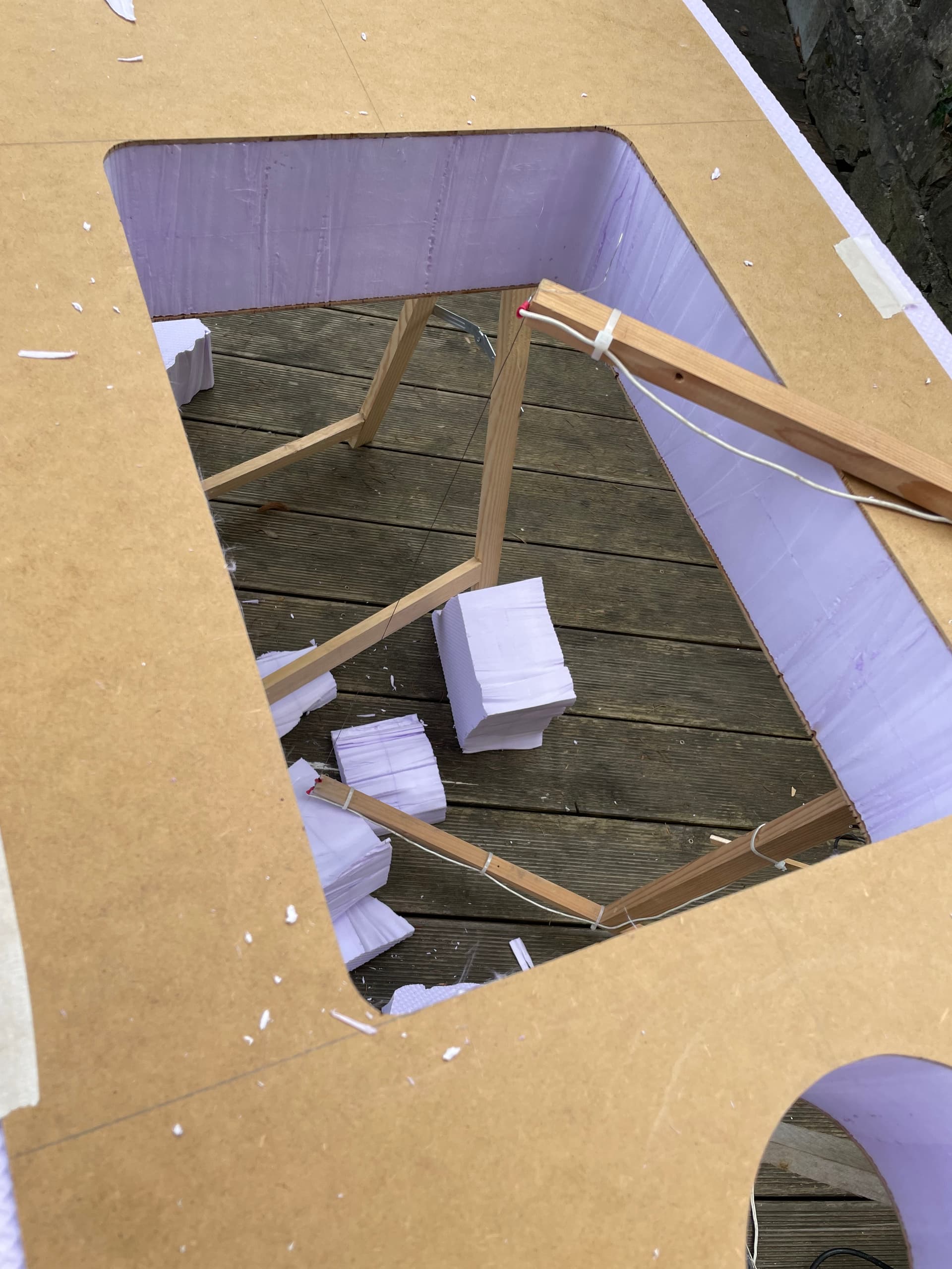
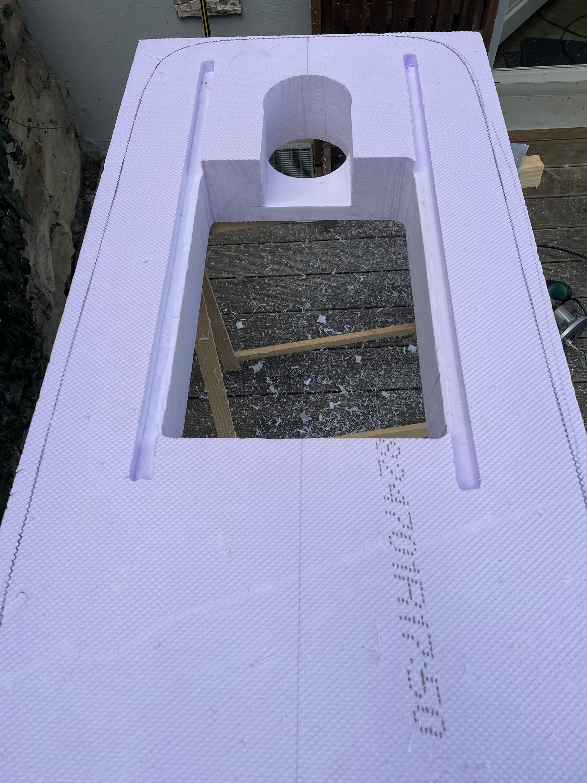
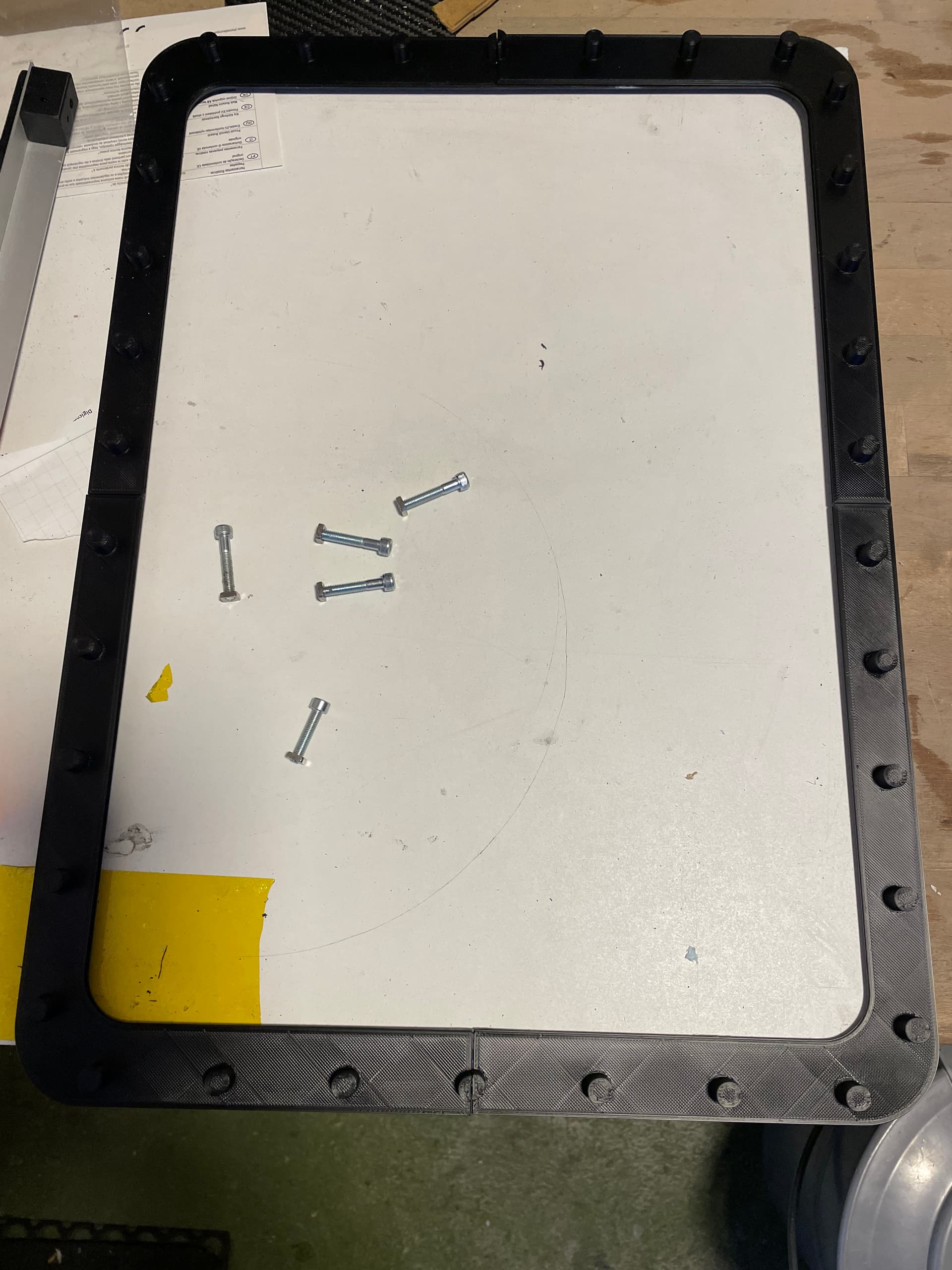
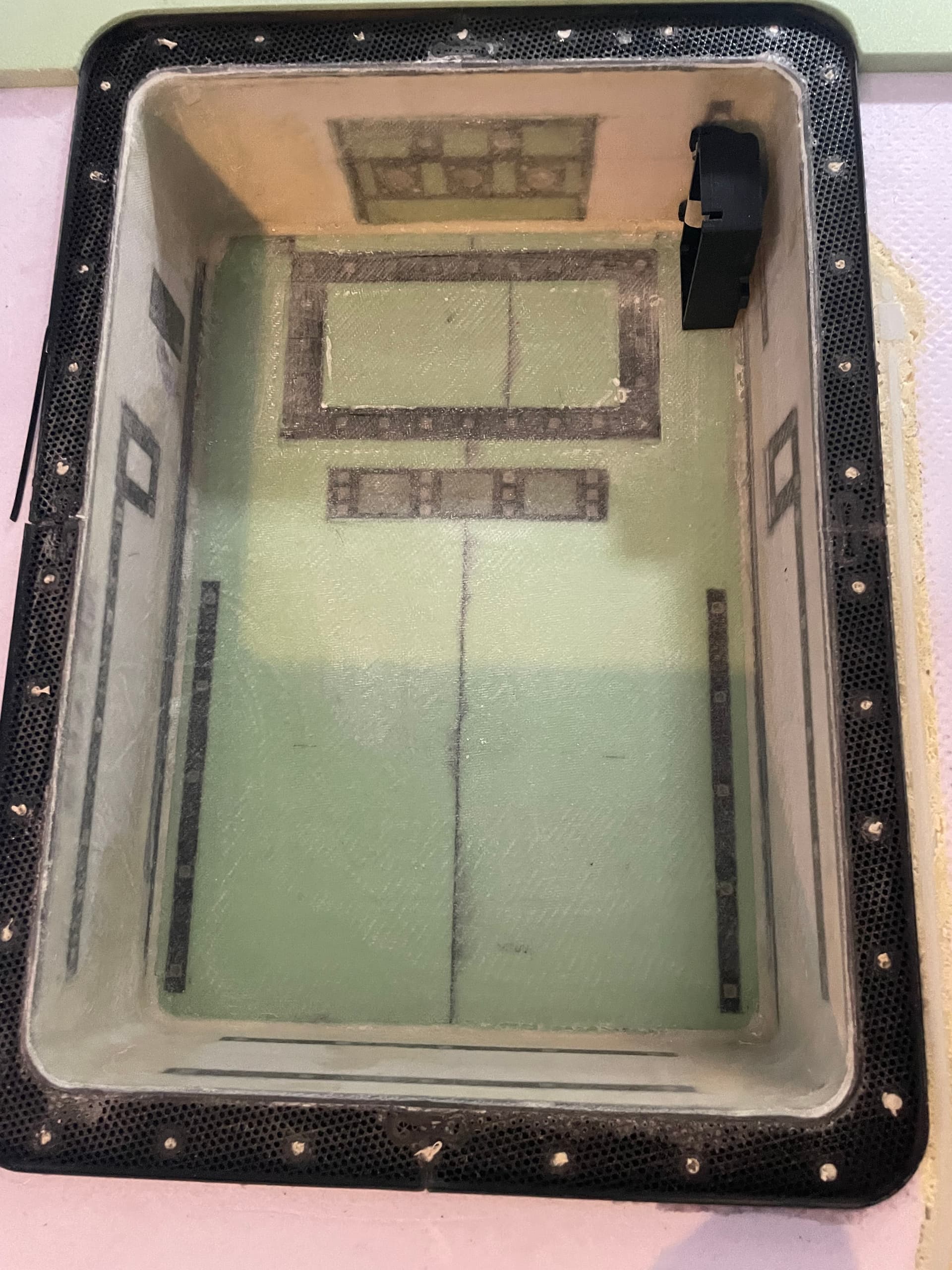
the mold consists of 2x4 segments that need to be glued together


spray glue to keep a sharp edge
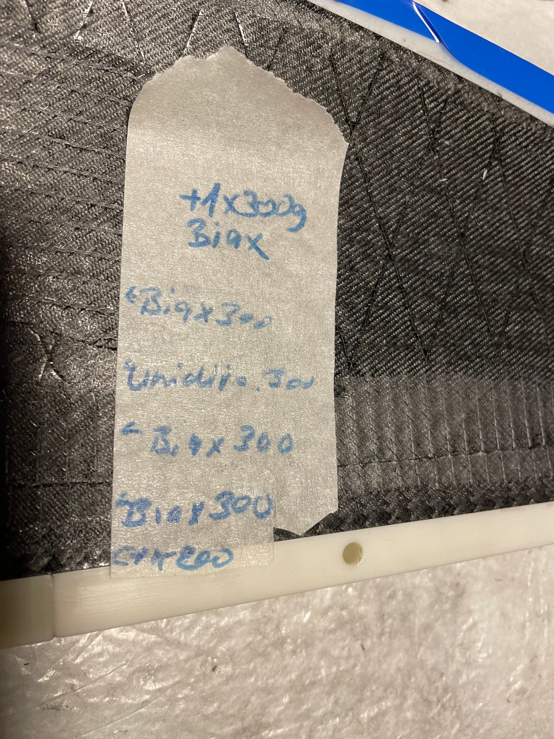
Layers from outside to inside
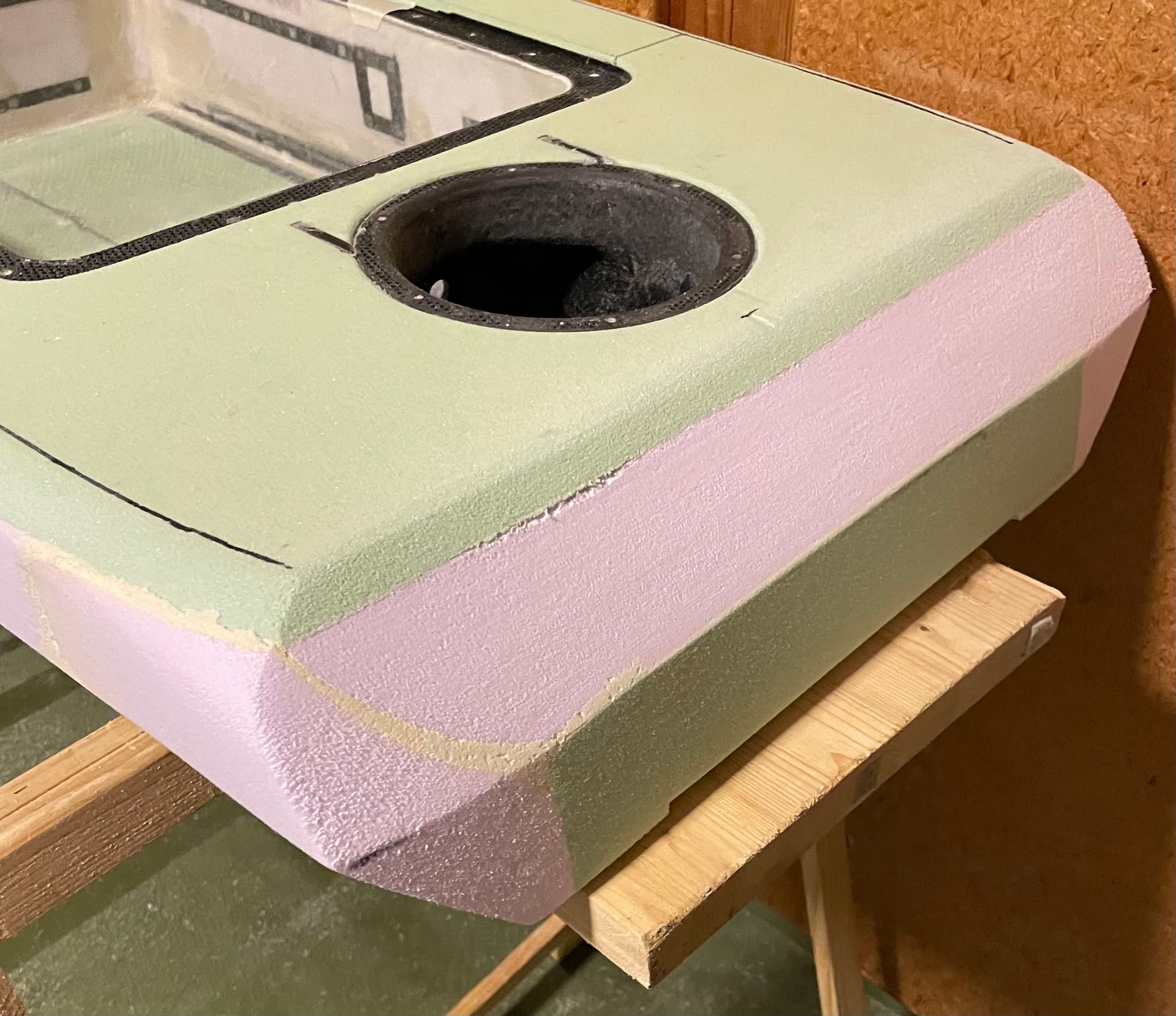
trim the cured halves to fit the mold

balsa wrapped in cfk
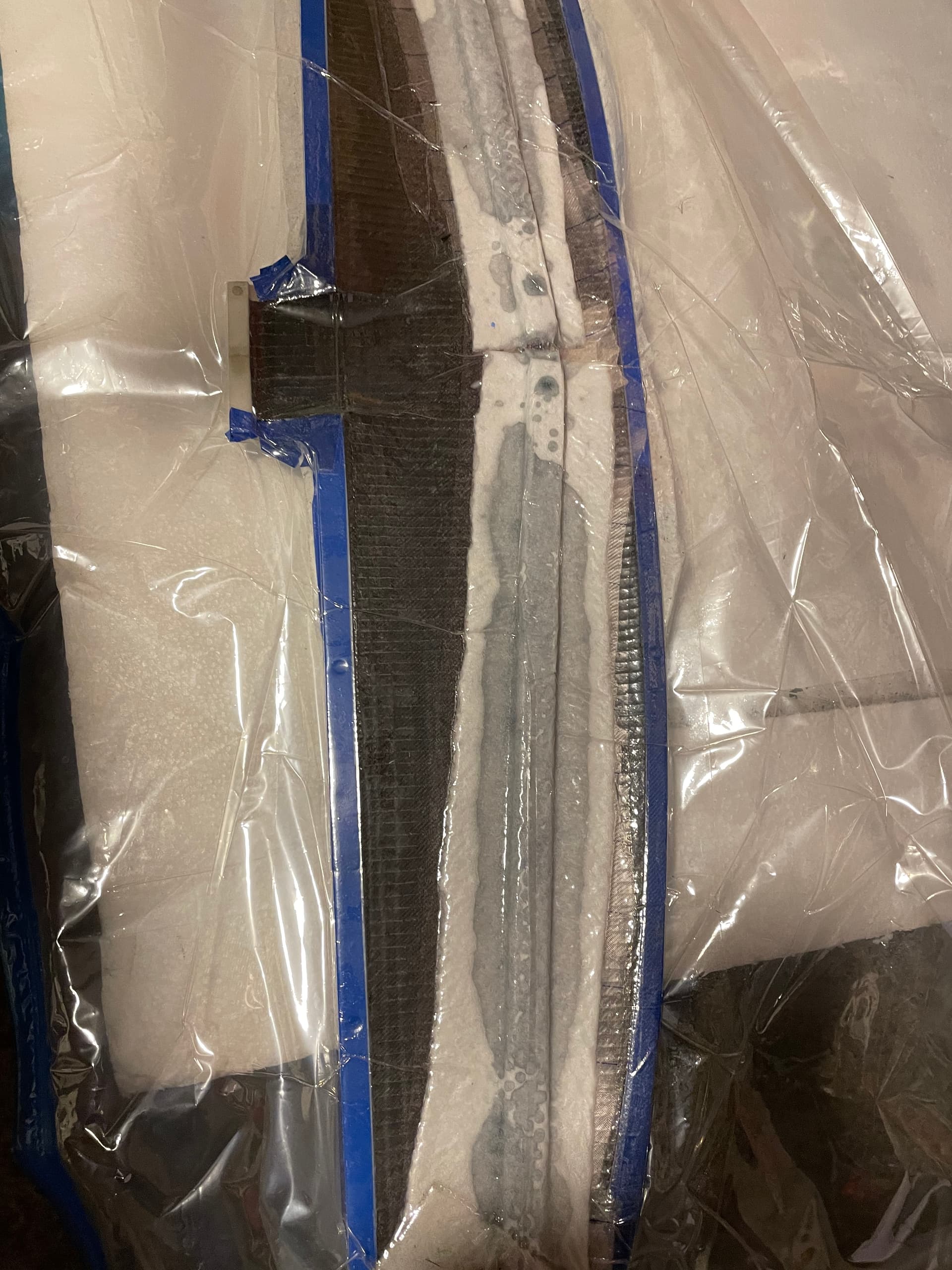
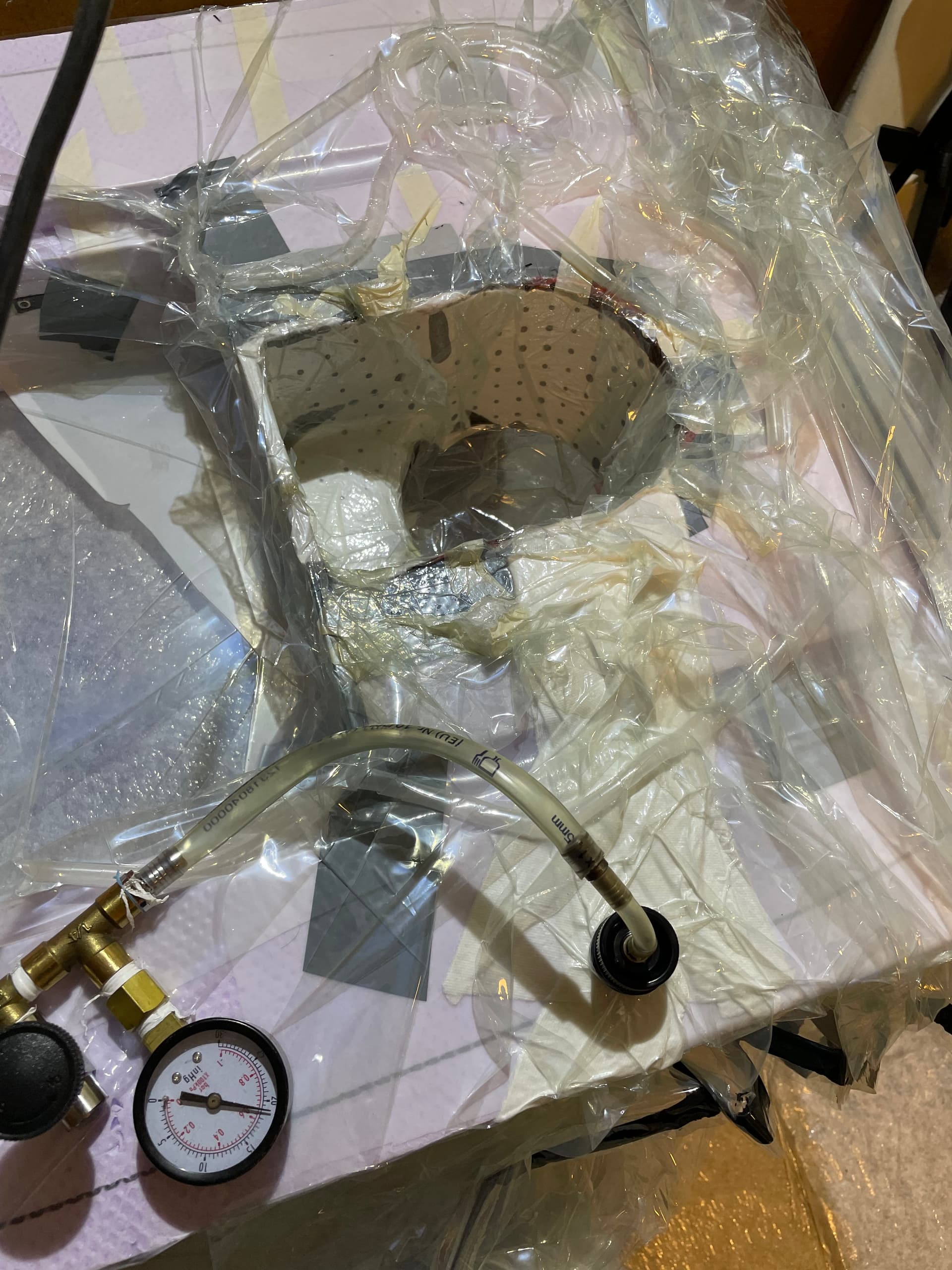
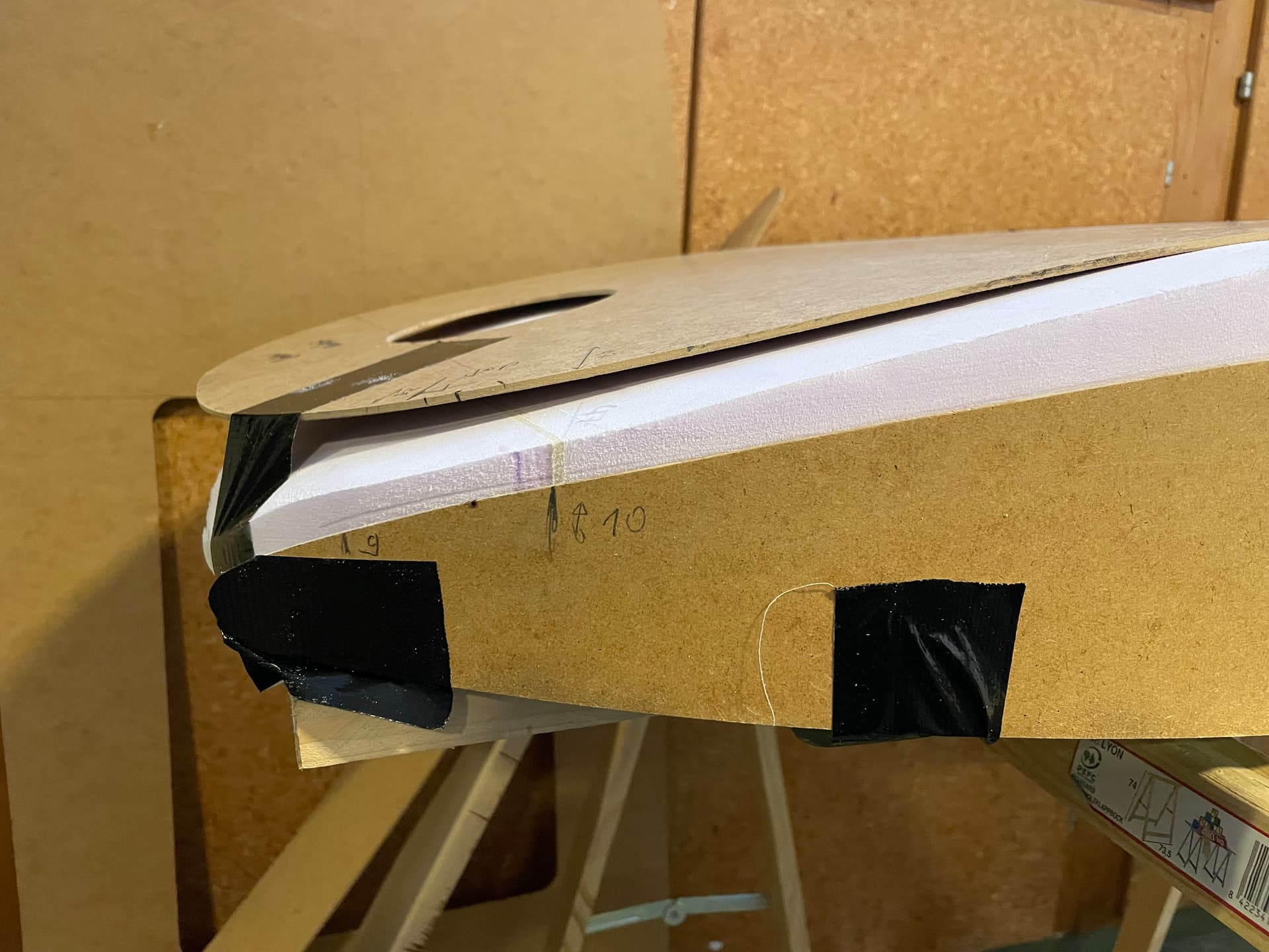
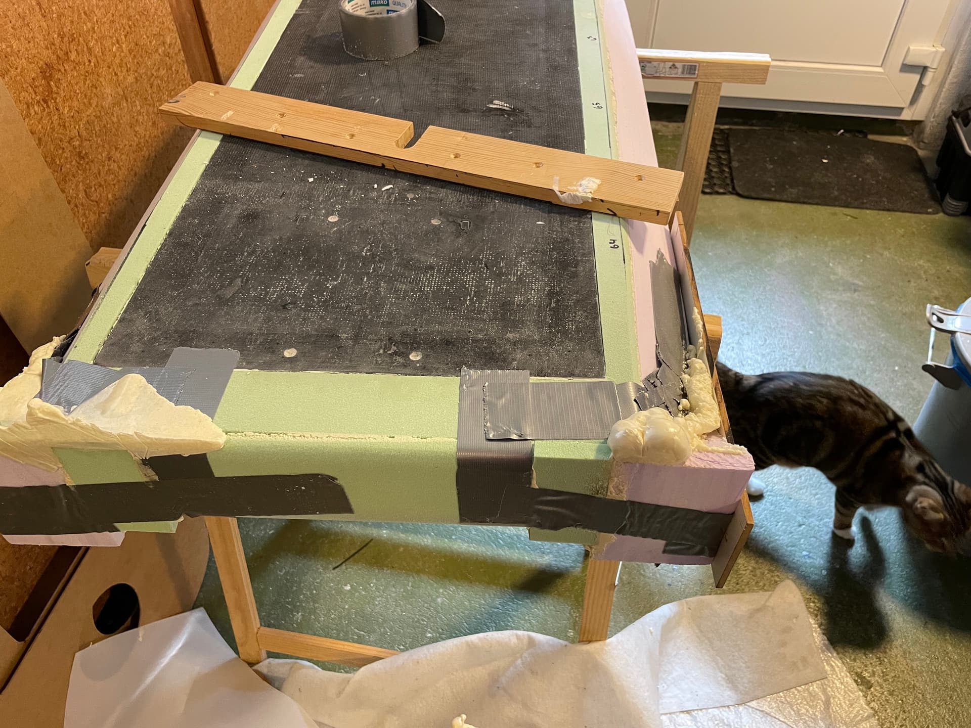
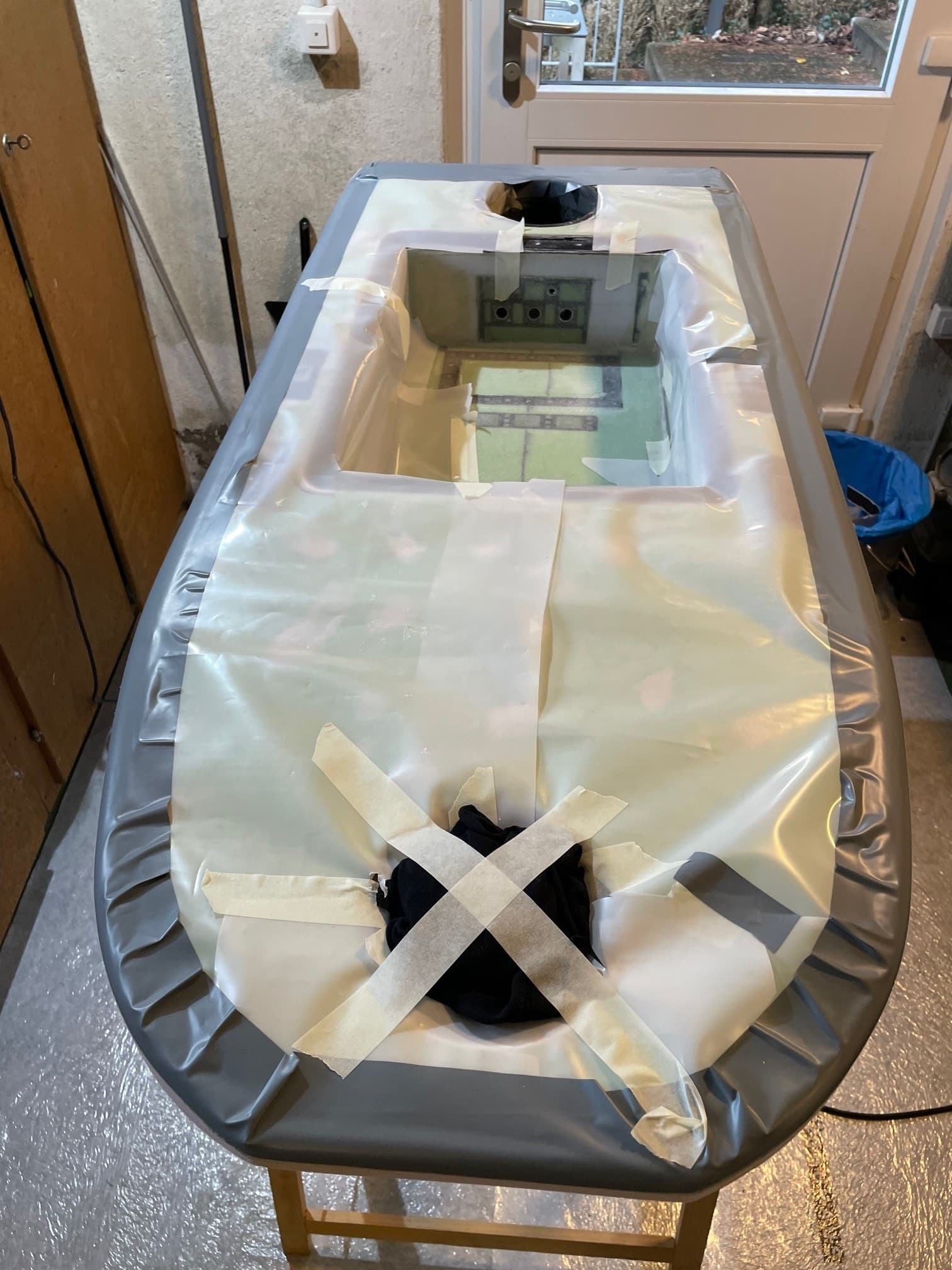
vacuum in position with film between the shell and the strut
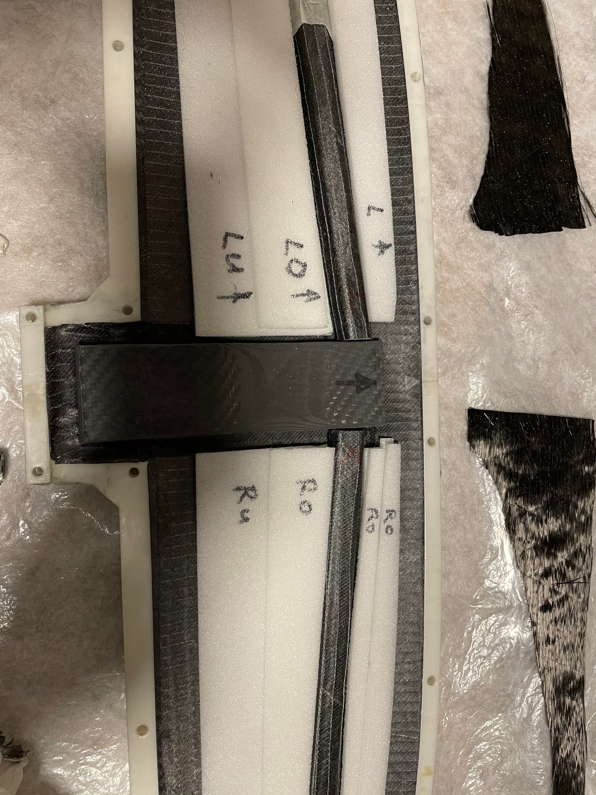
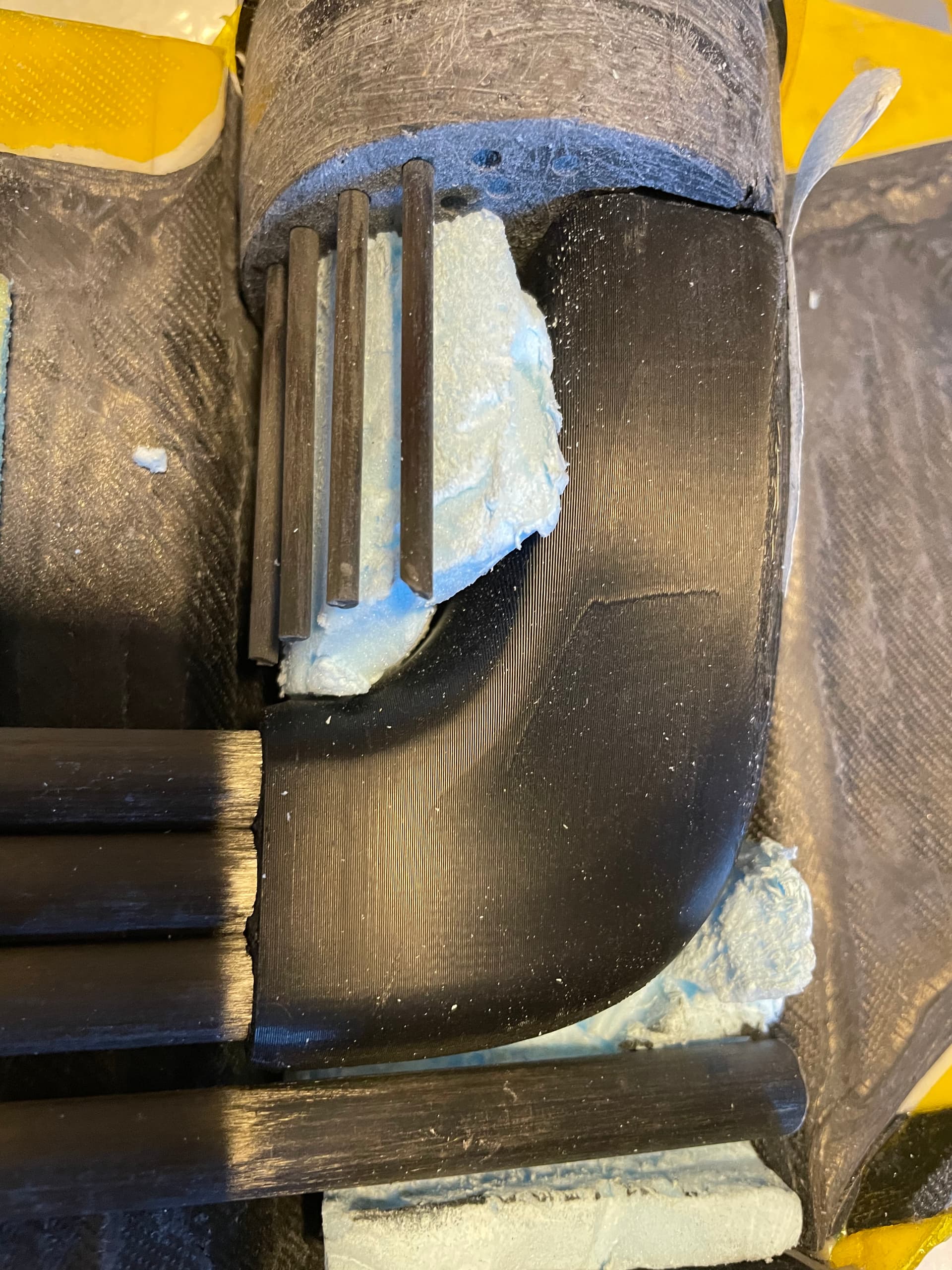
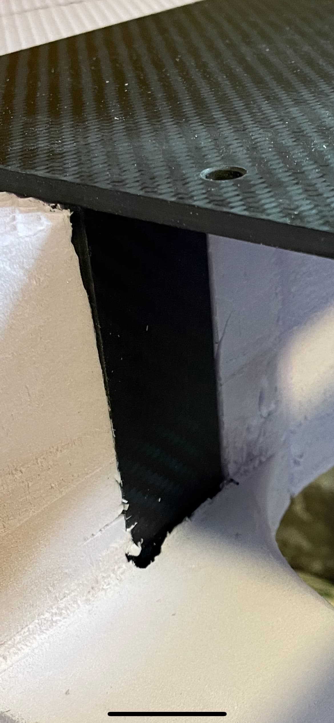
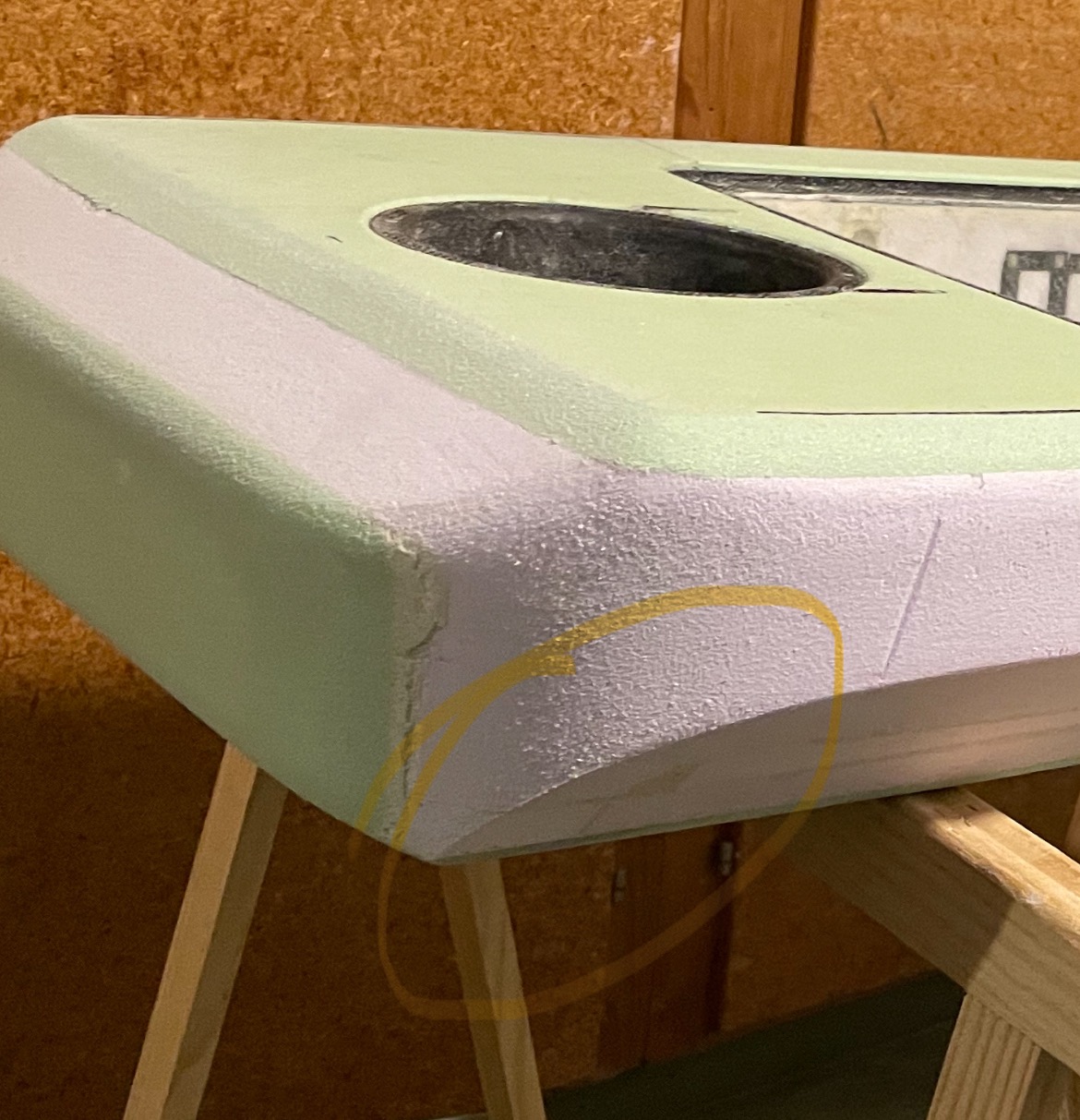
add some 50g/m3 foam, sanded to fit

fill with thickened epoxy mixed with micro ballons and cfk flakes
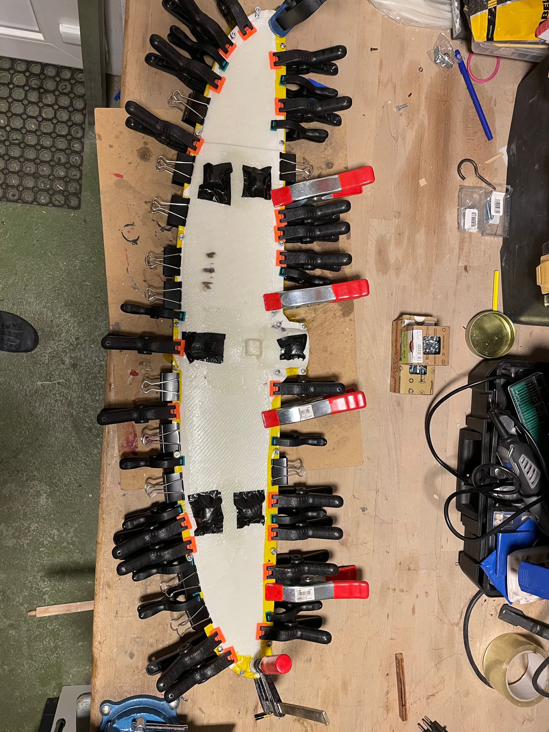
close an cure with camps
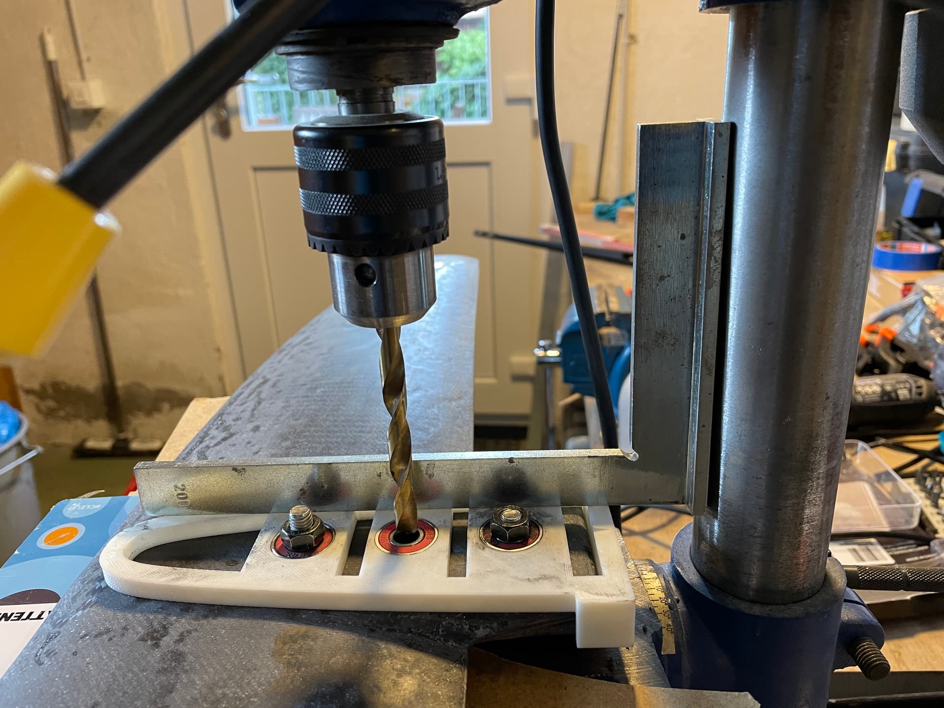
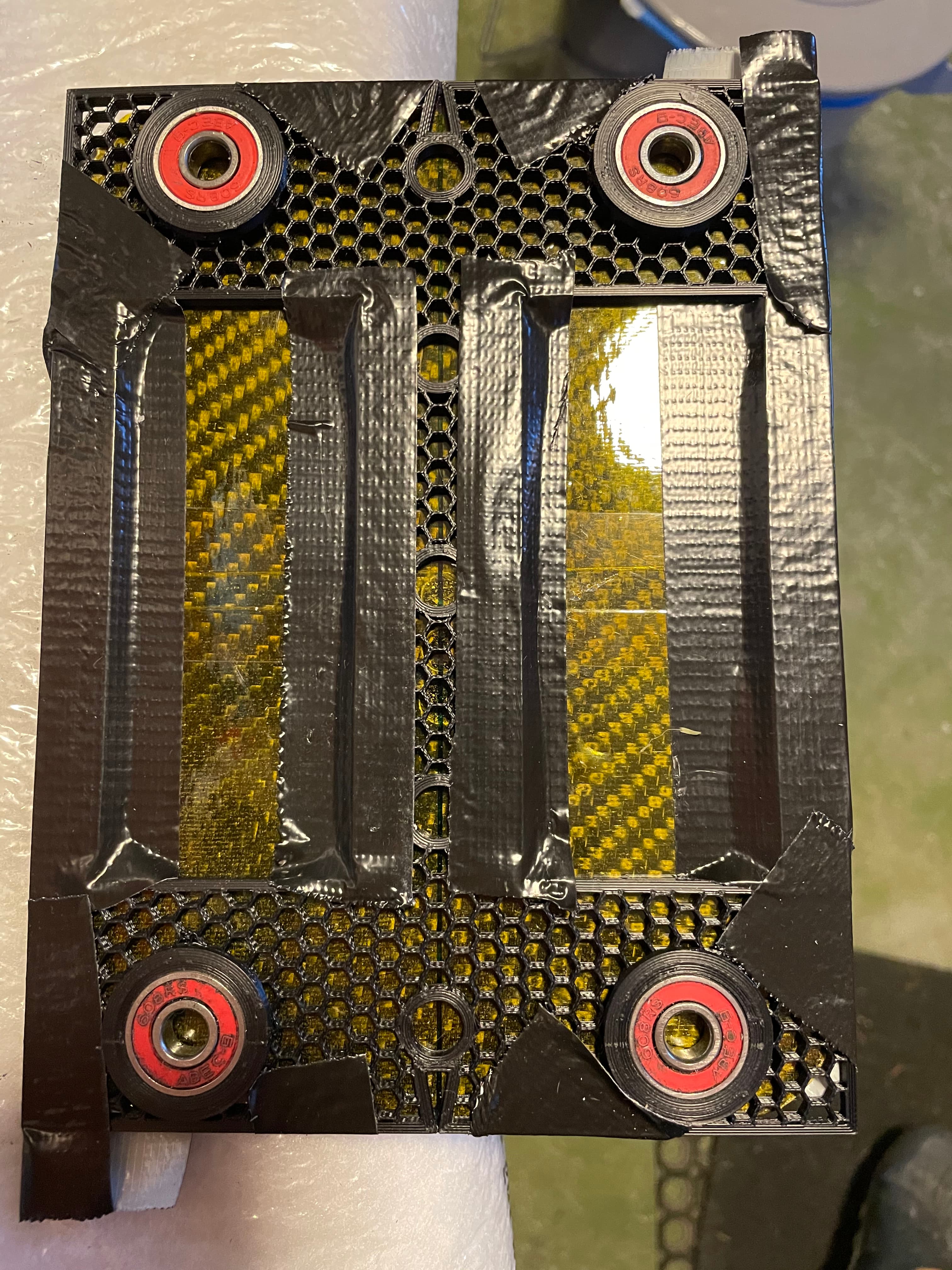
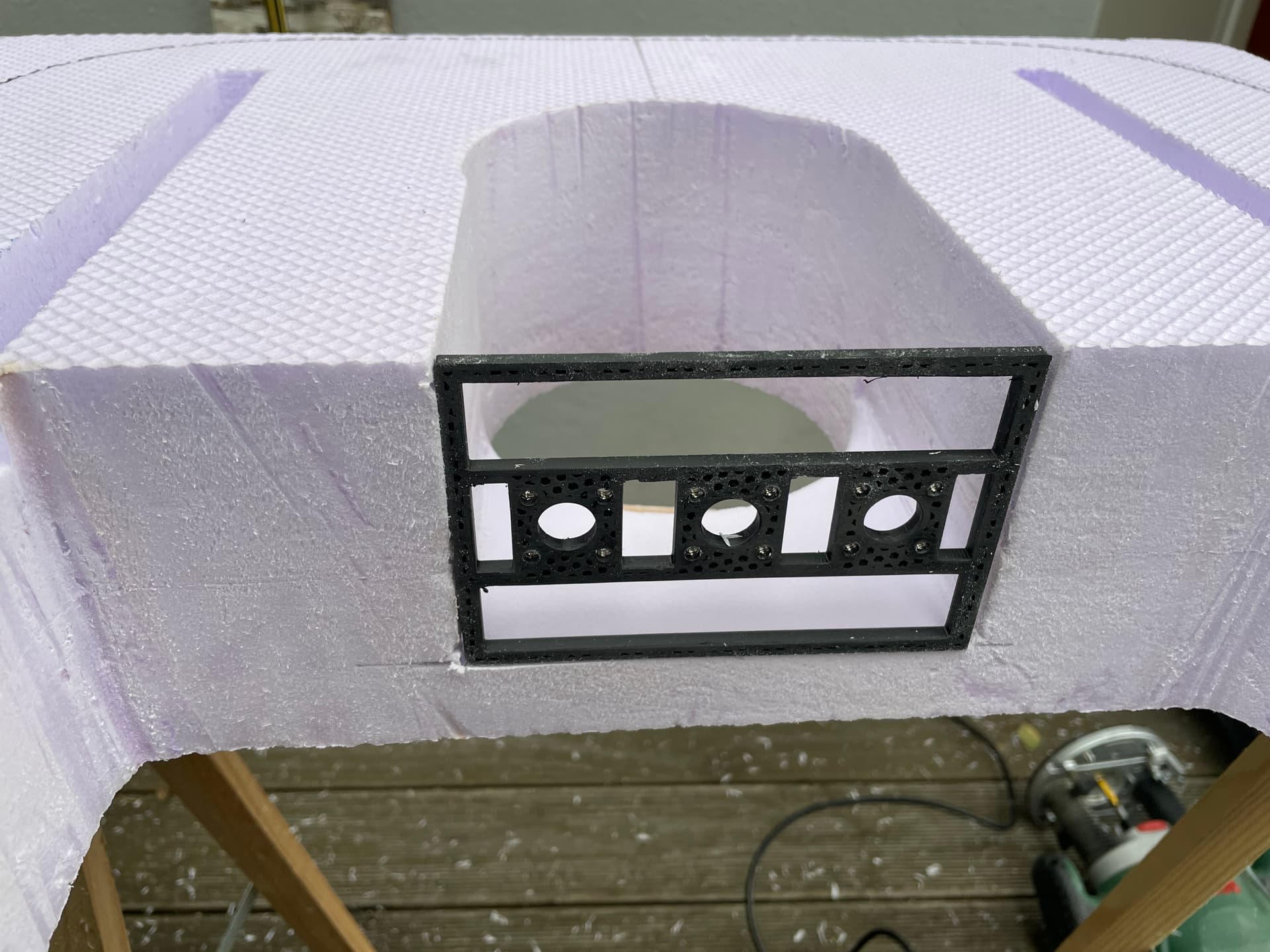
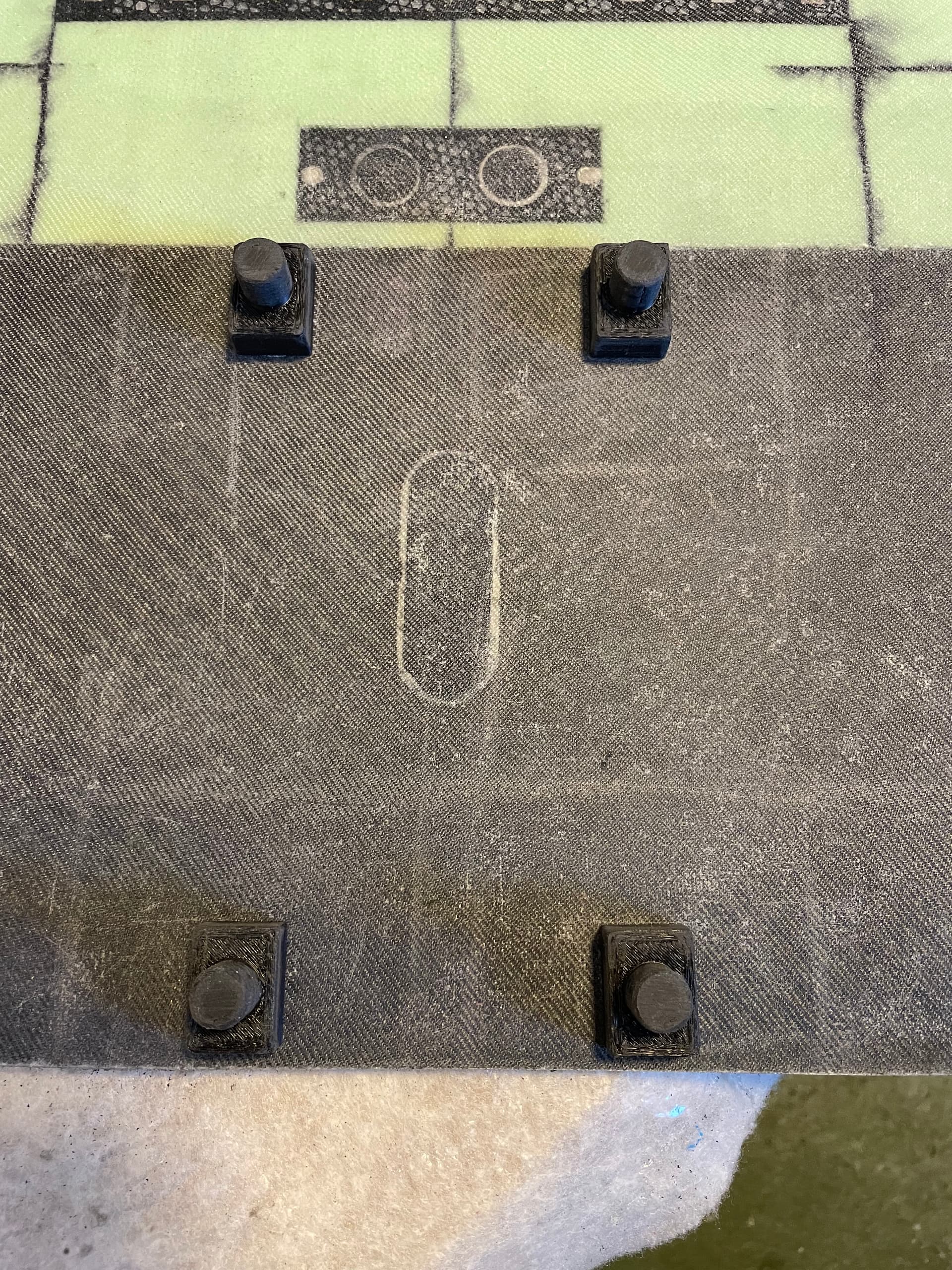
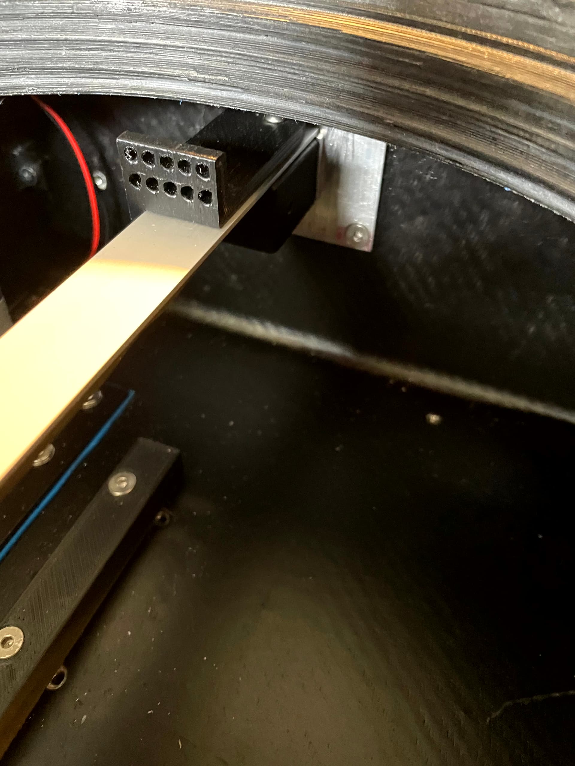
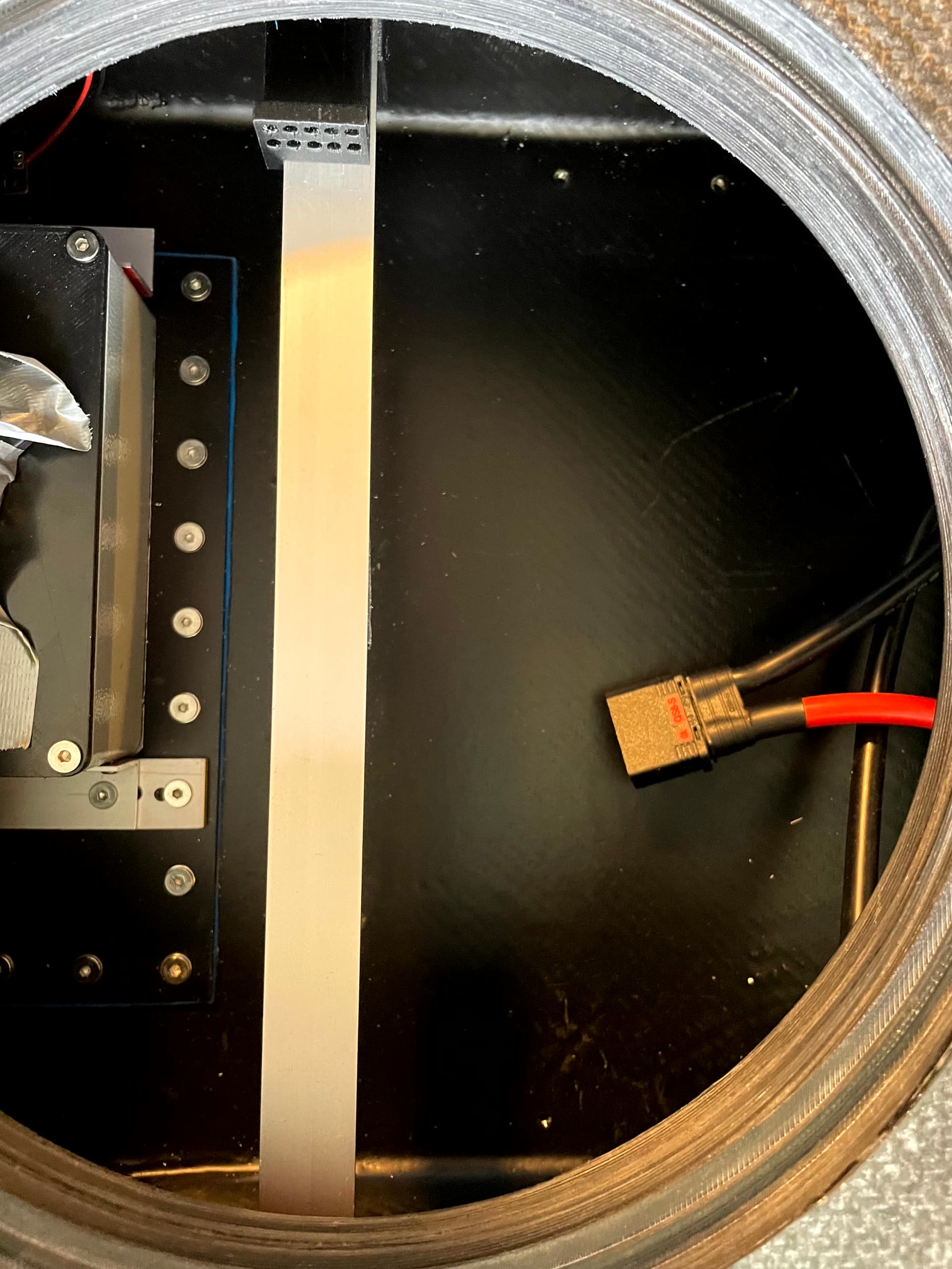
drill jig
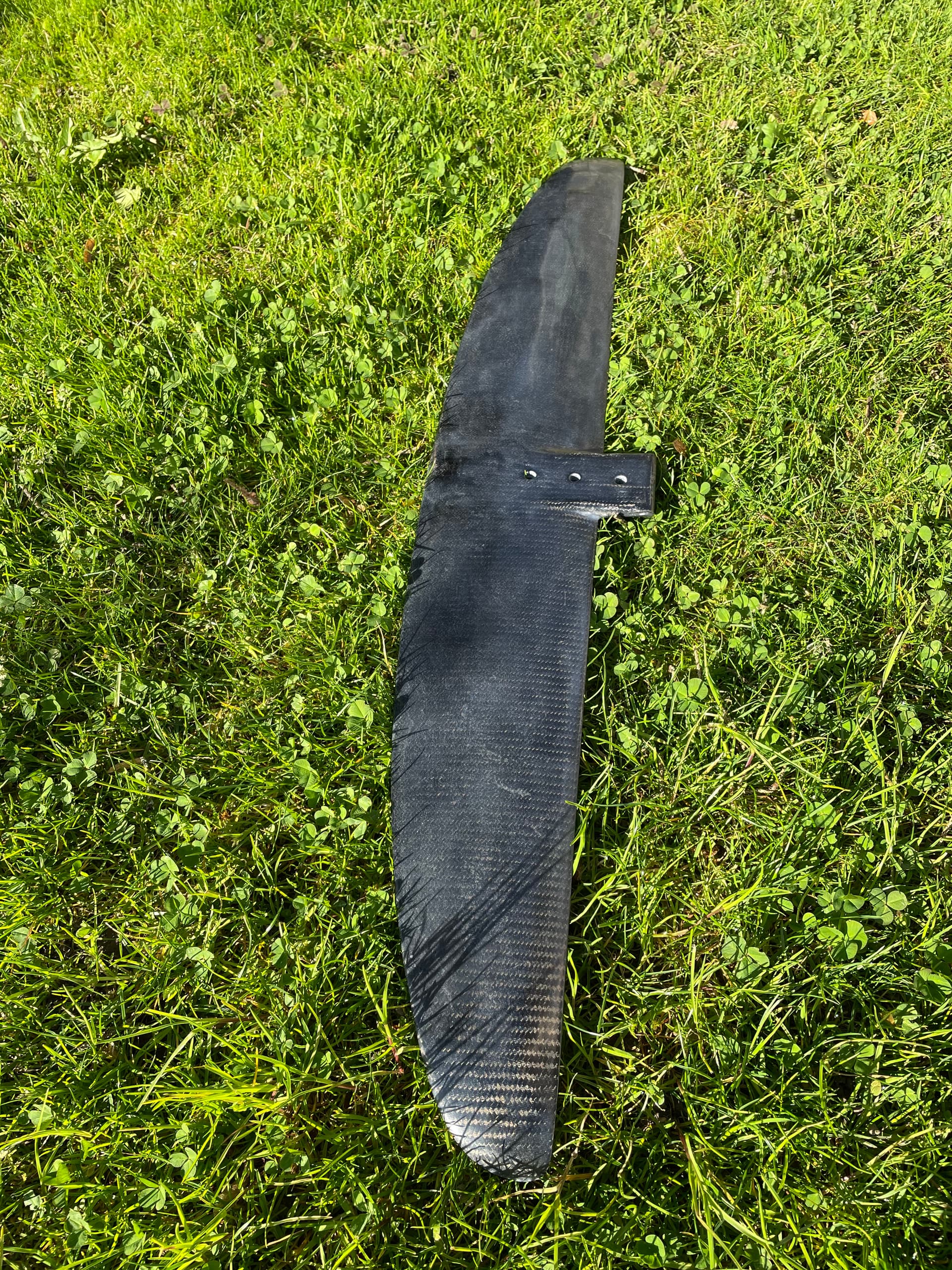
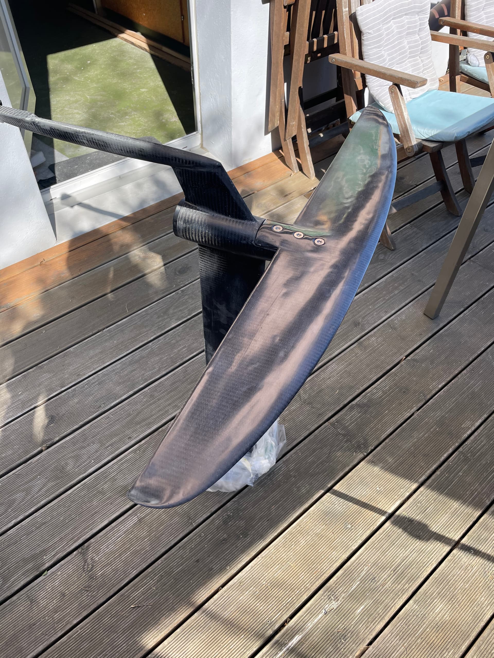
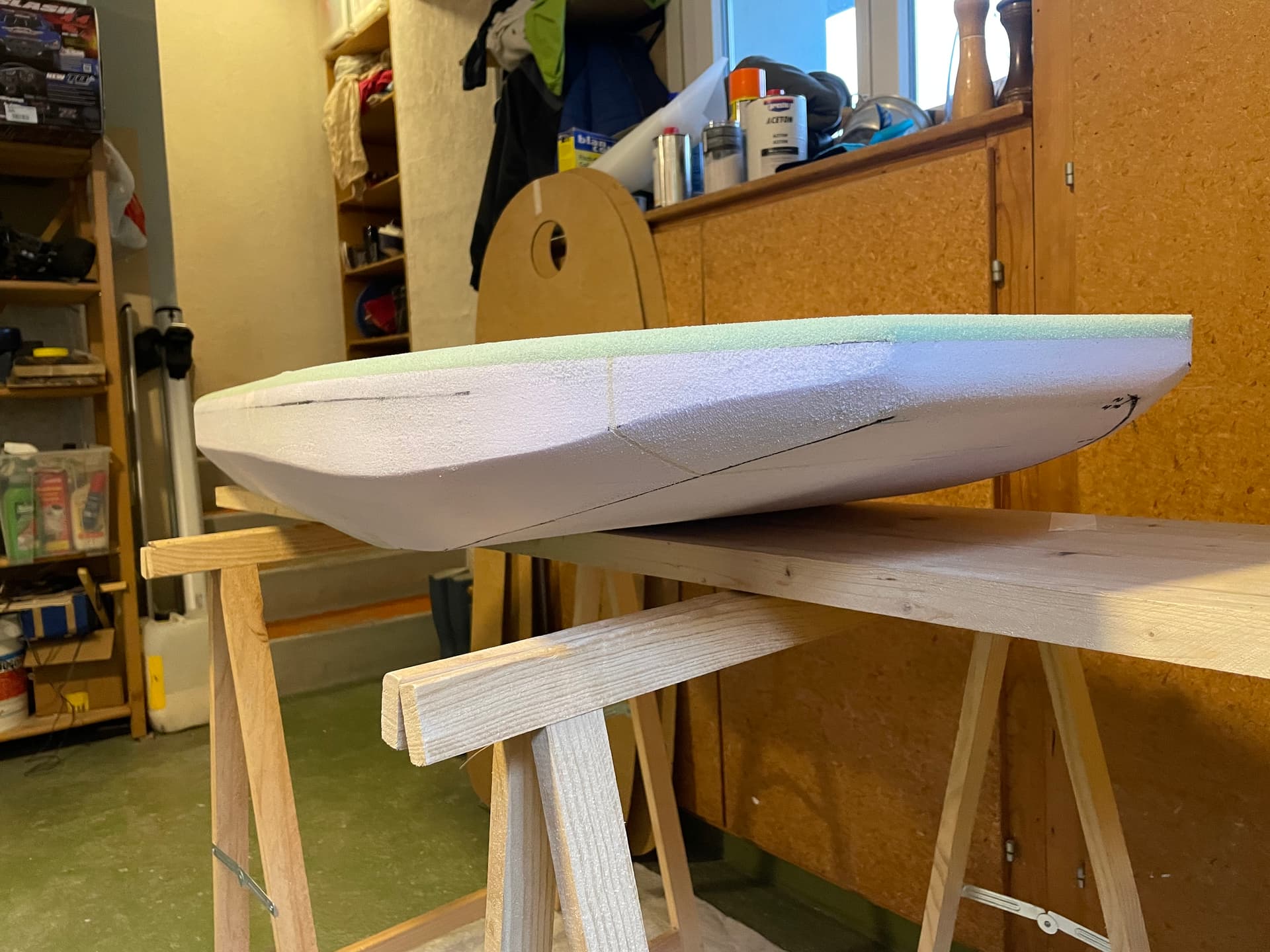
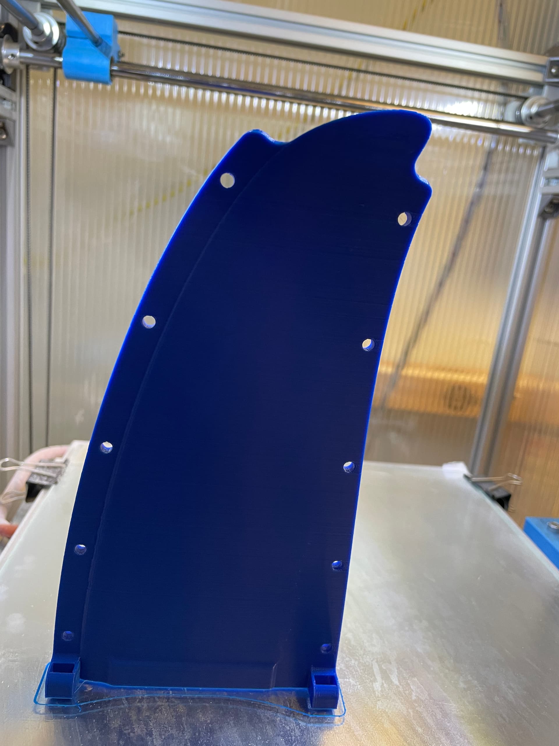
end result