Finally finished my build after more than two years. When I started there were next to no dedicated parts for e-foils available, therefore I built most of it myself. It was fun but took too much time.
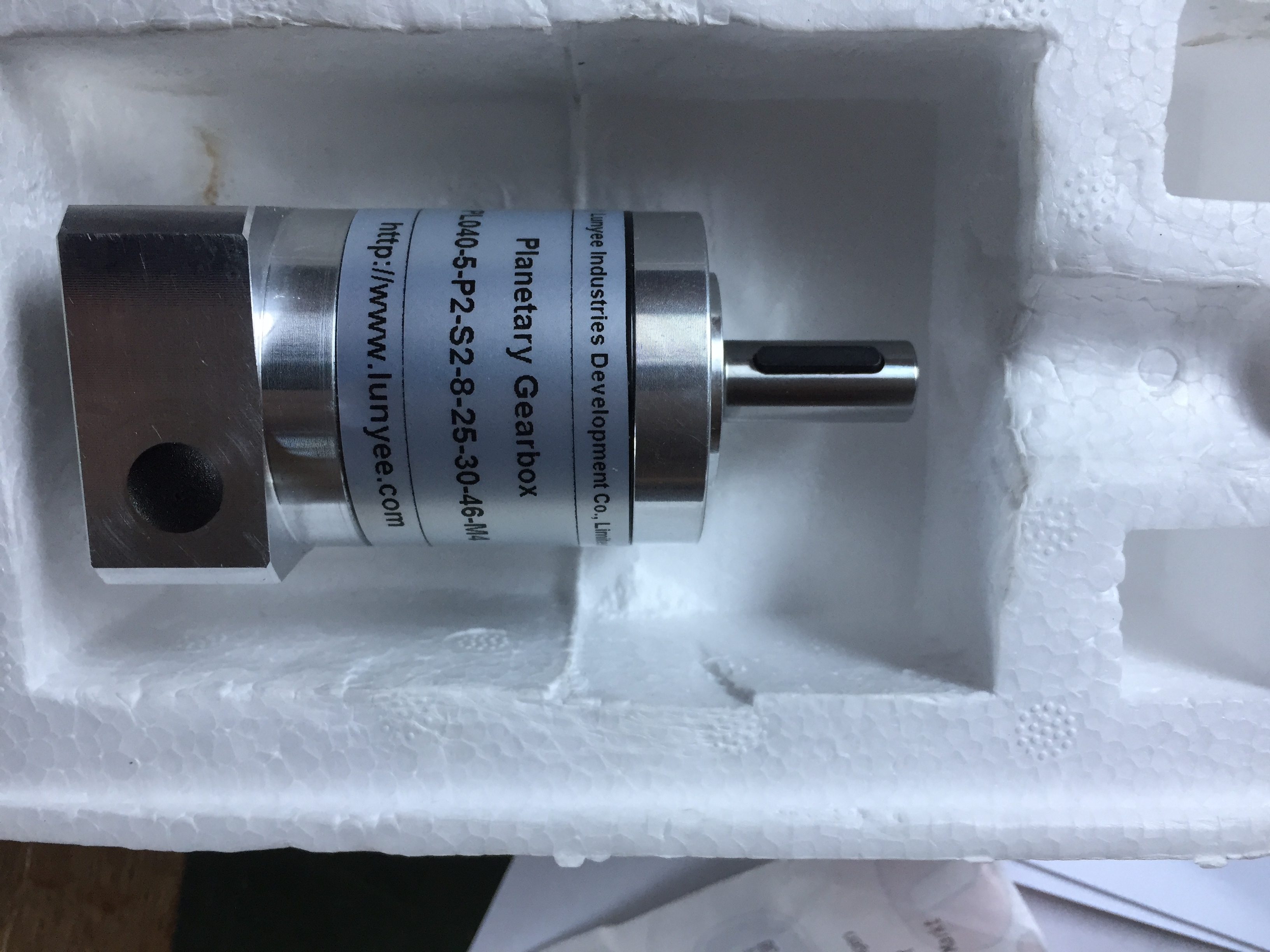
I started with a geared setup like Pacificmeister and the Hiorth brothers. As it was difficult and expensive to get a 5:1 Neugarth gear, I got a Chinese clone from Alibaba.
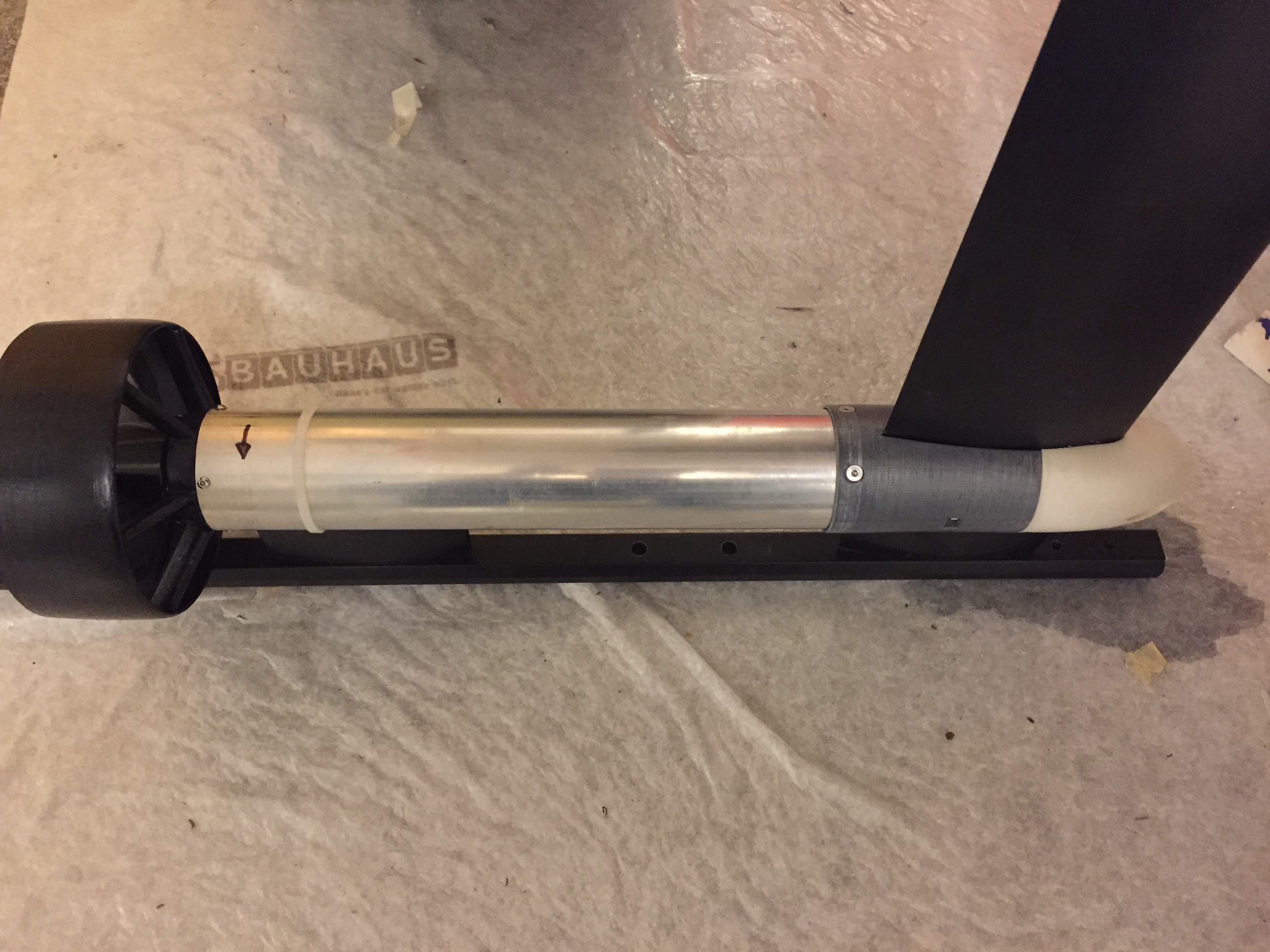
POD
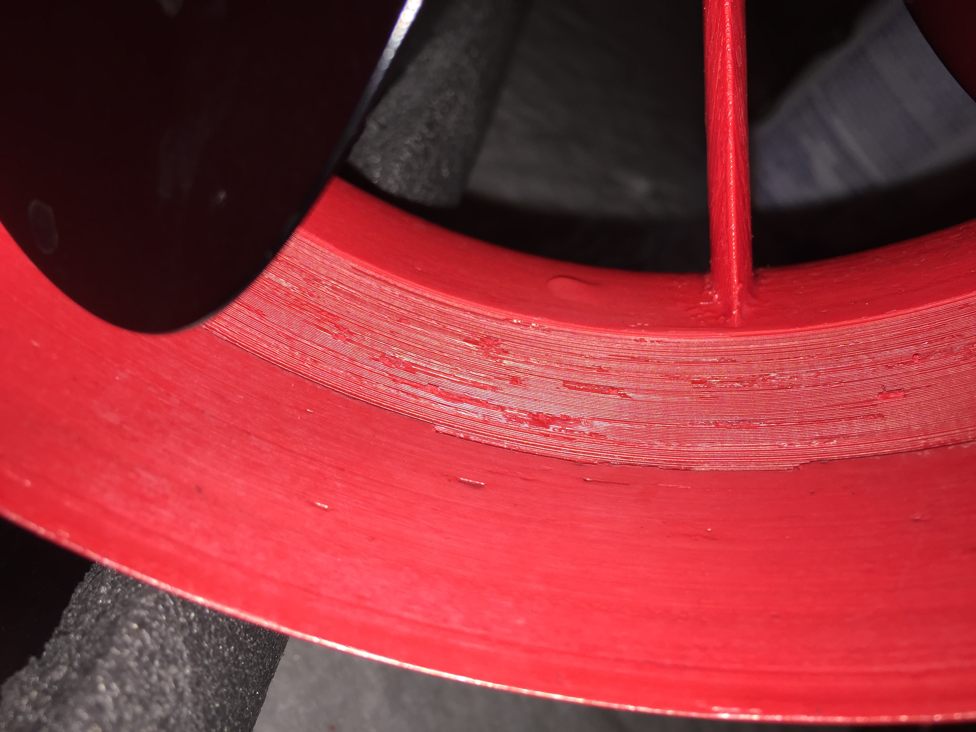
1st iteration with 3D printed motor mount and back part: (in red)
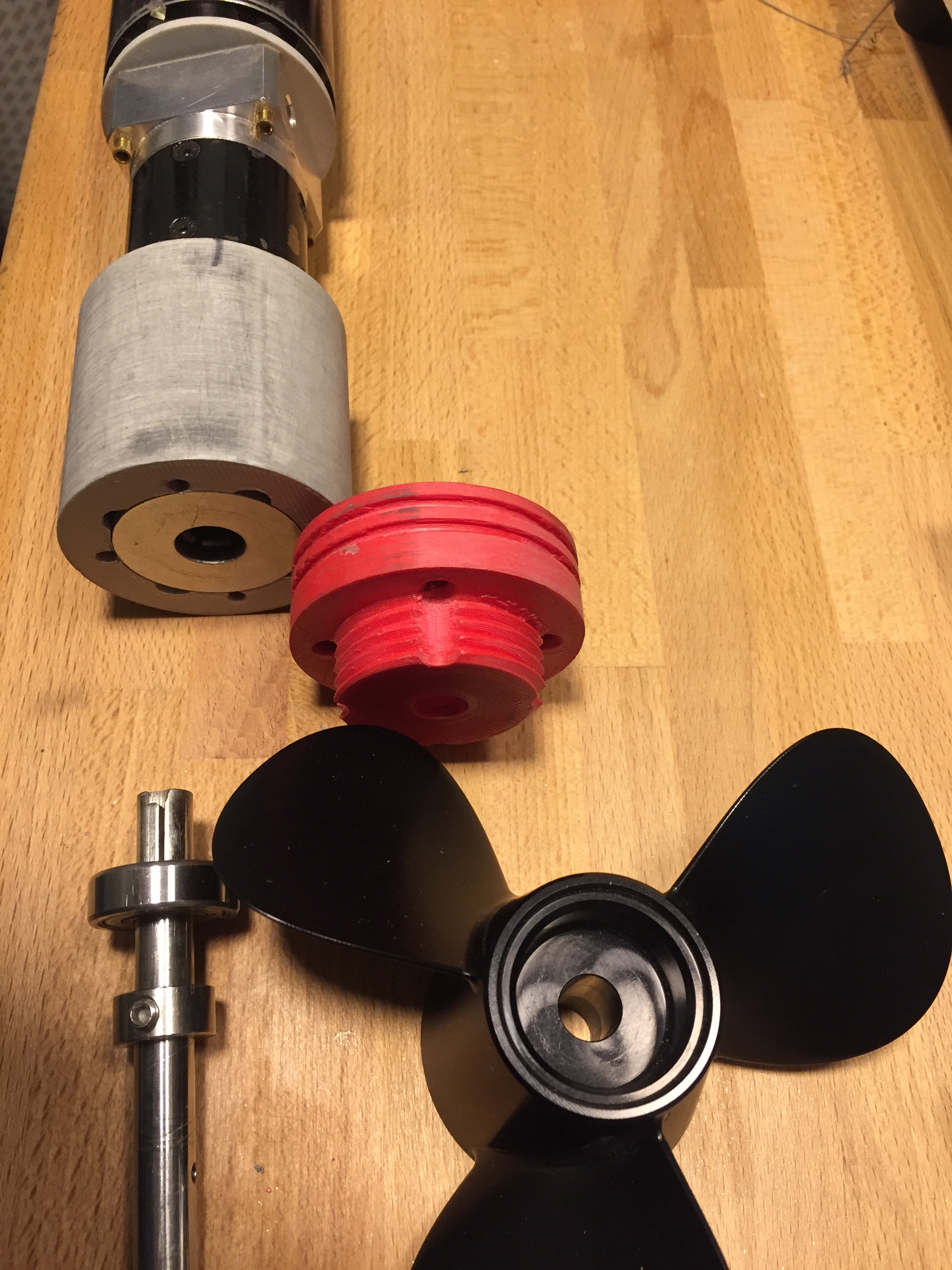
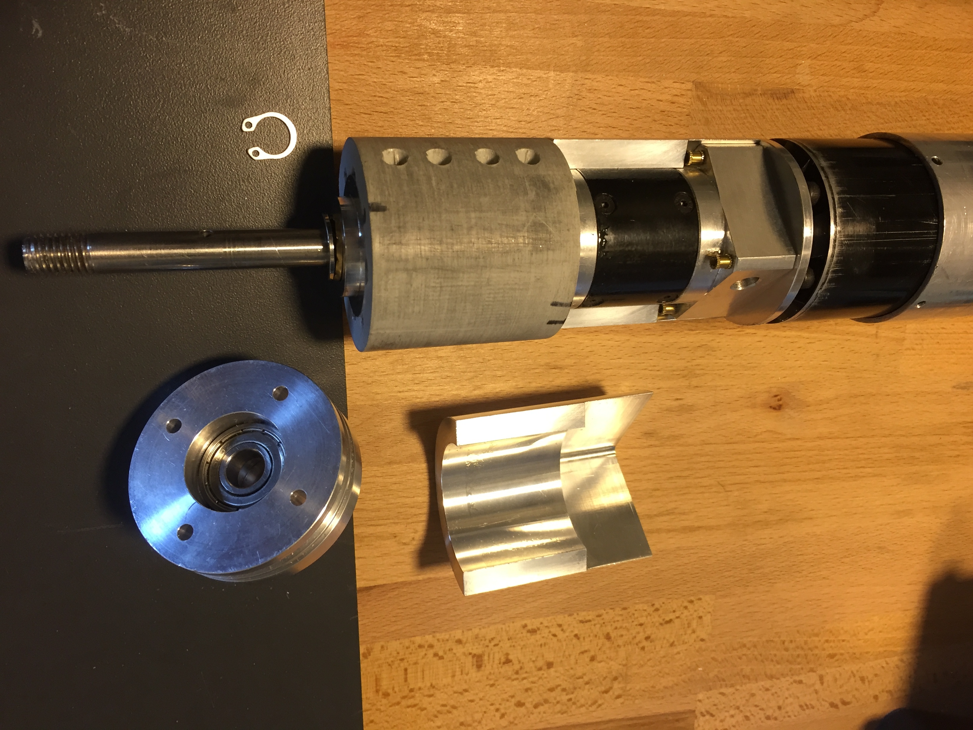
2nd iteration with lathed Parts:
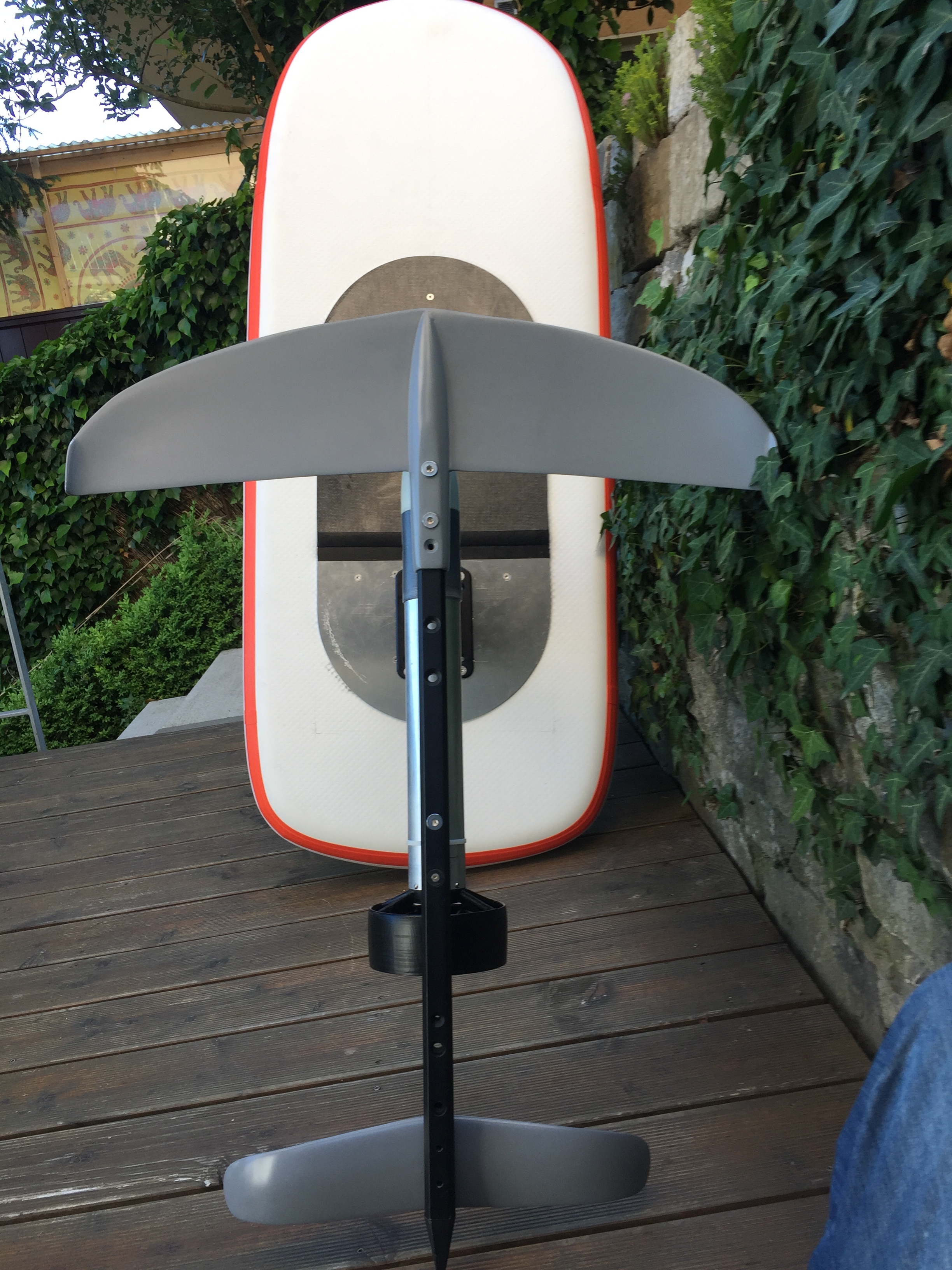
![IMG_7552|375x500]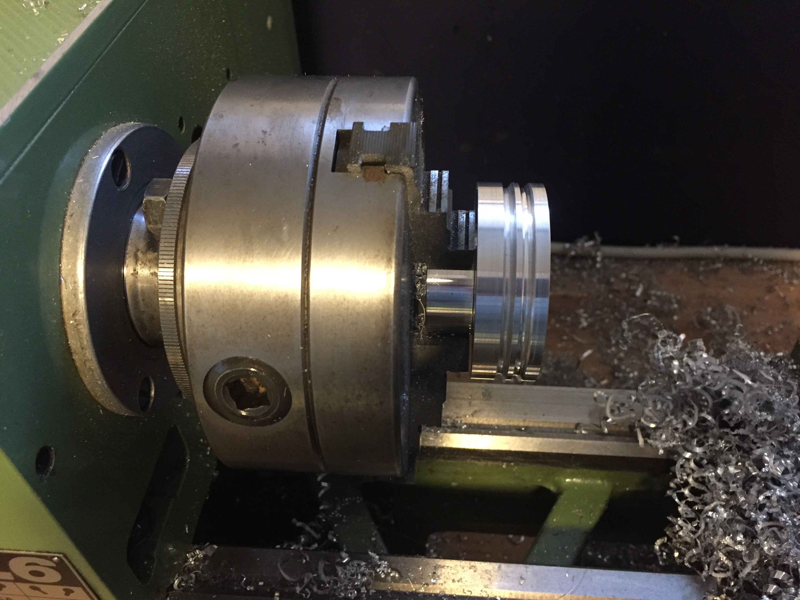
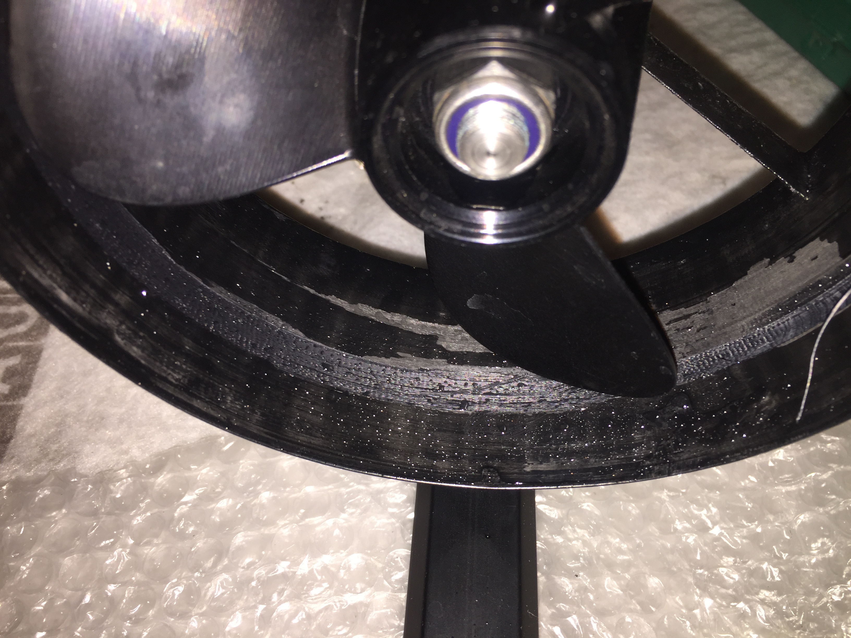
Got a milled part from China to cool the gear, also added a thrust bearing to prevent axial load to the gear.
(upload://uAU5t6I3RaBQumOGzNzleBajmpJ.jpeg)
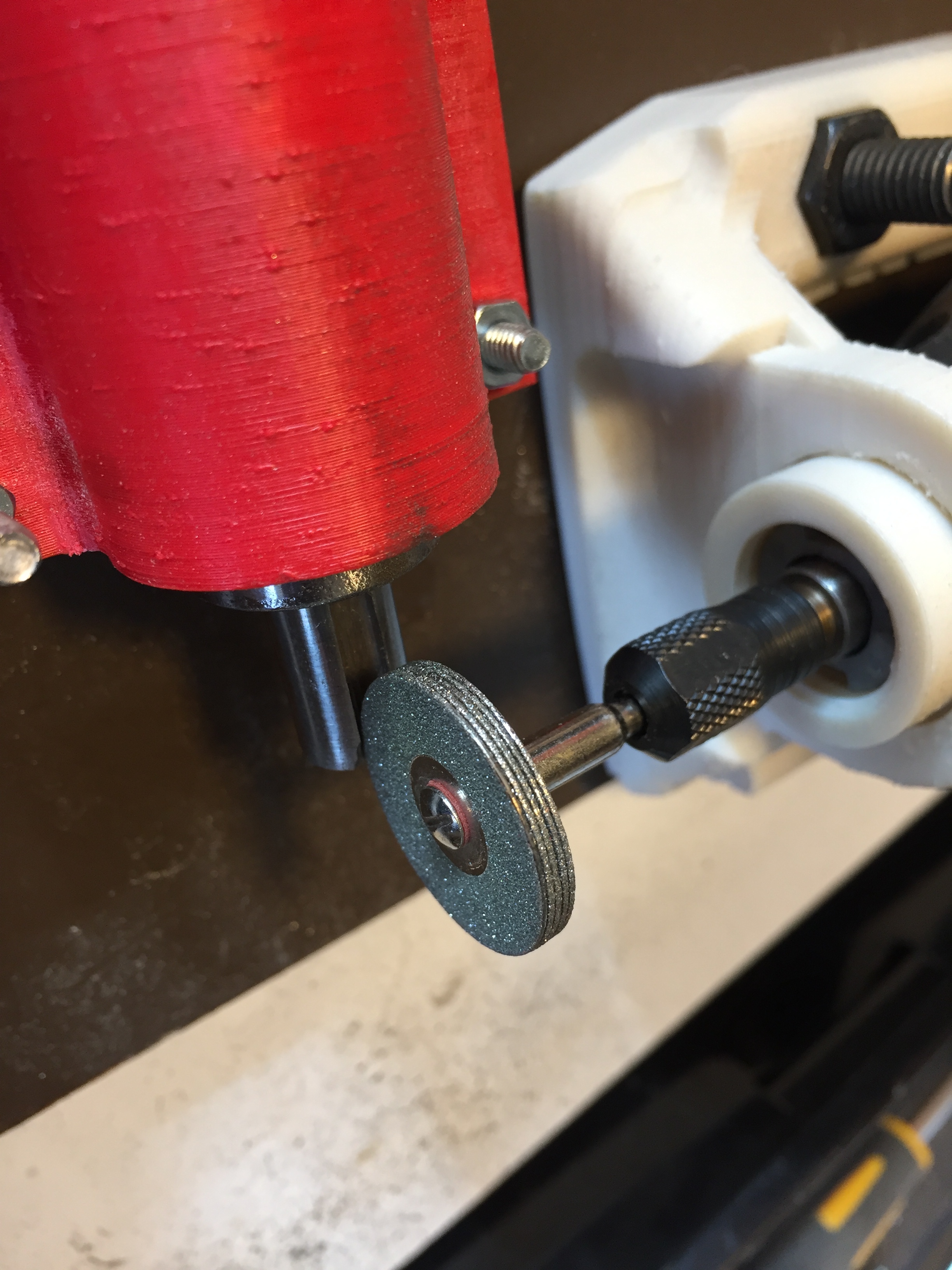
Cut a slot in the stainless steel shaft with a dremel in a 3D printed sliding tool
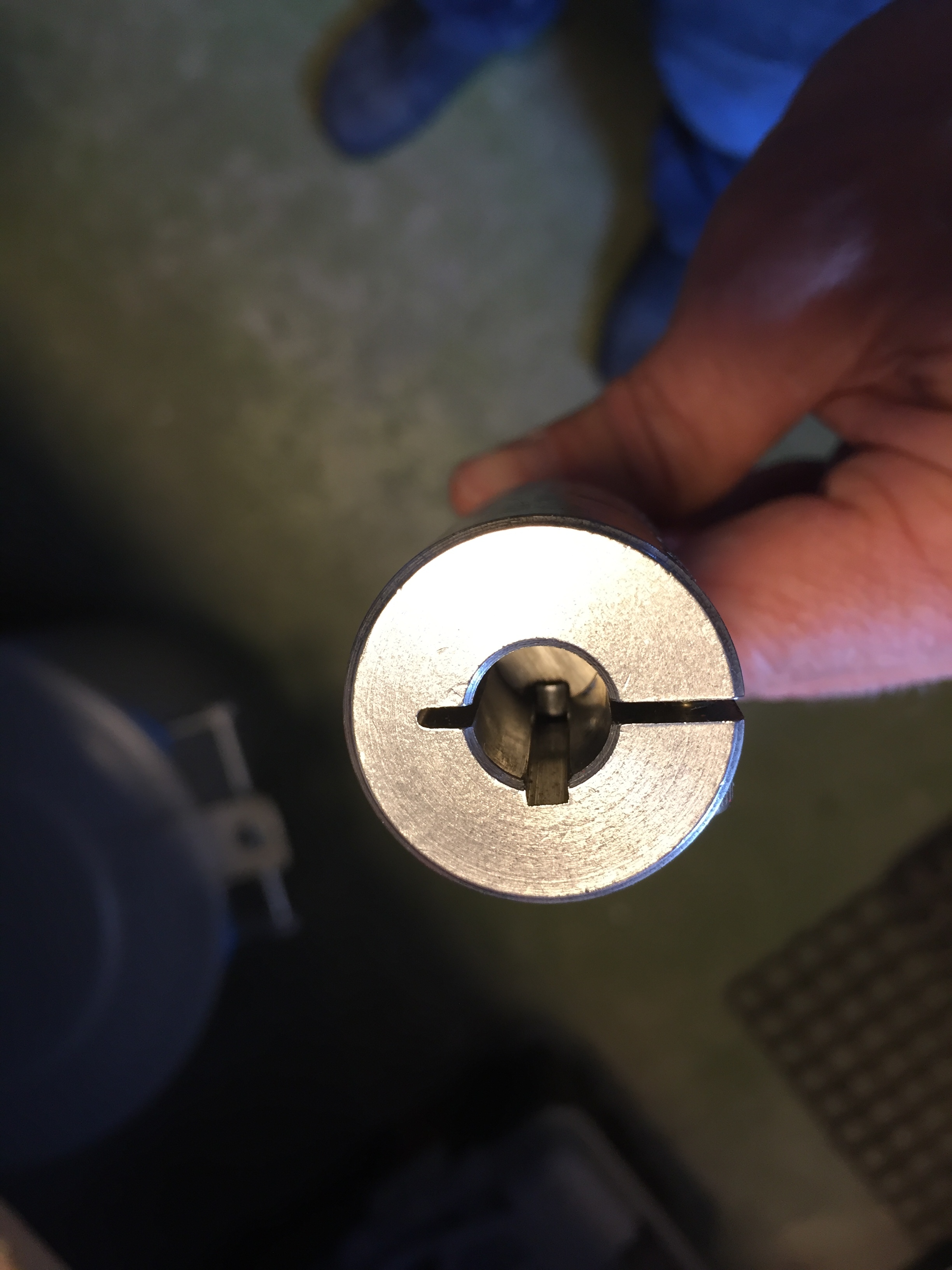
Coupler with a slot, shaft with key inside. This is a quite massive coupler, which is one of the reasons my pod is so long. I also balanced the couppler with an angle grinder to minimize vibrations as it has a bit of mass. Read to many posts of broken couplers…
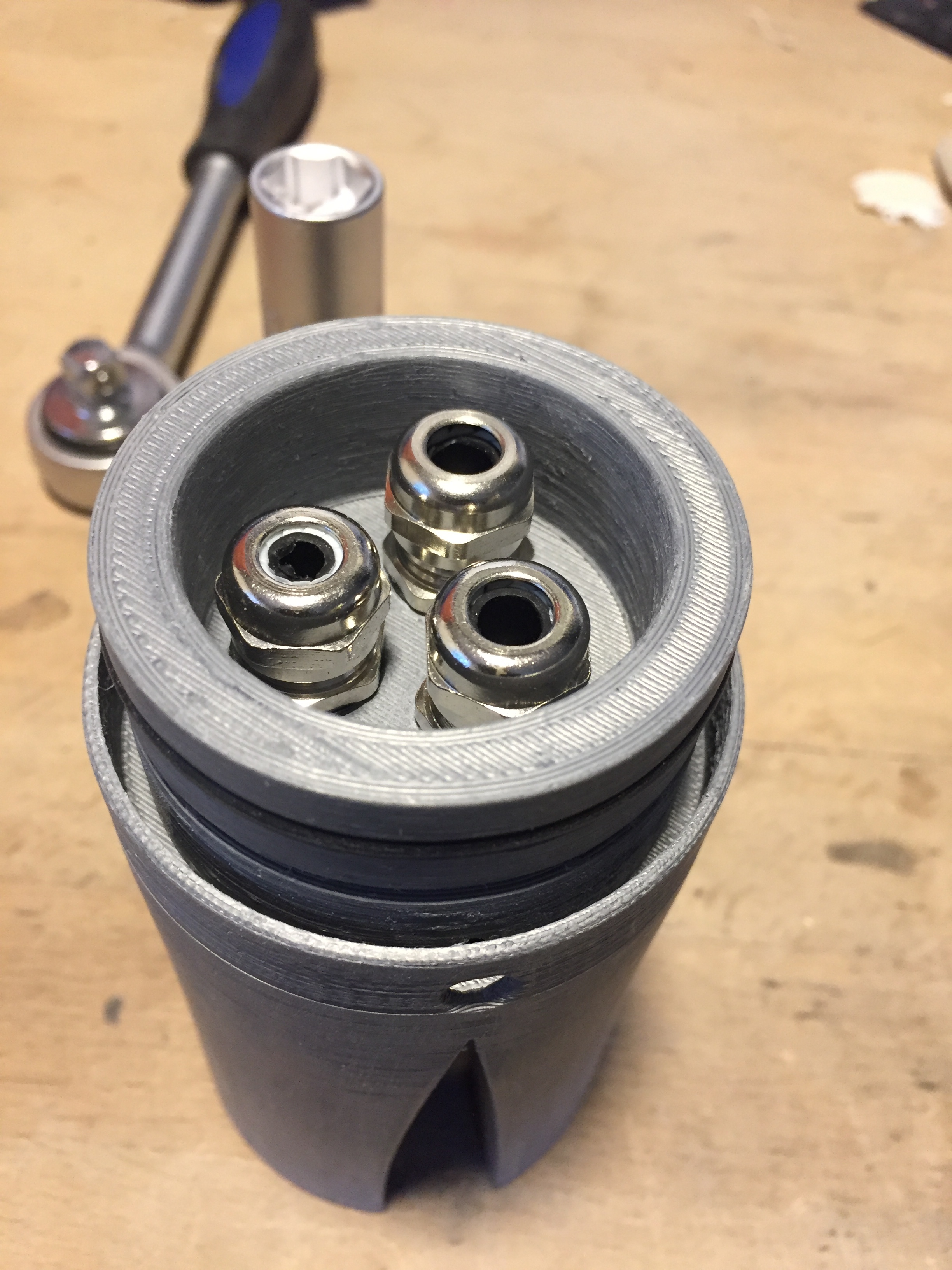
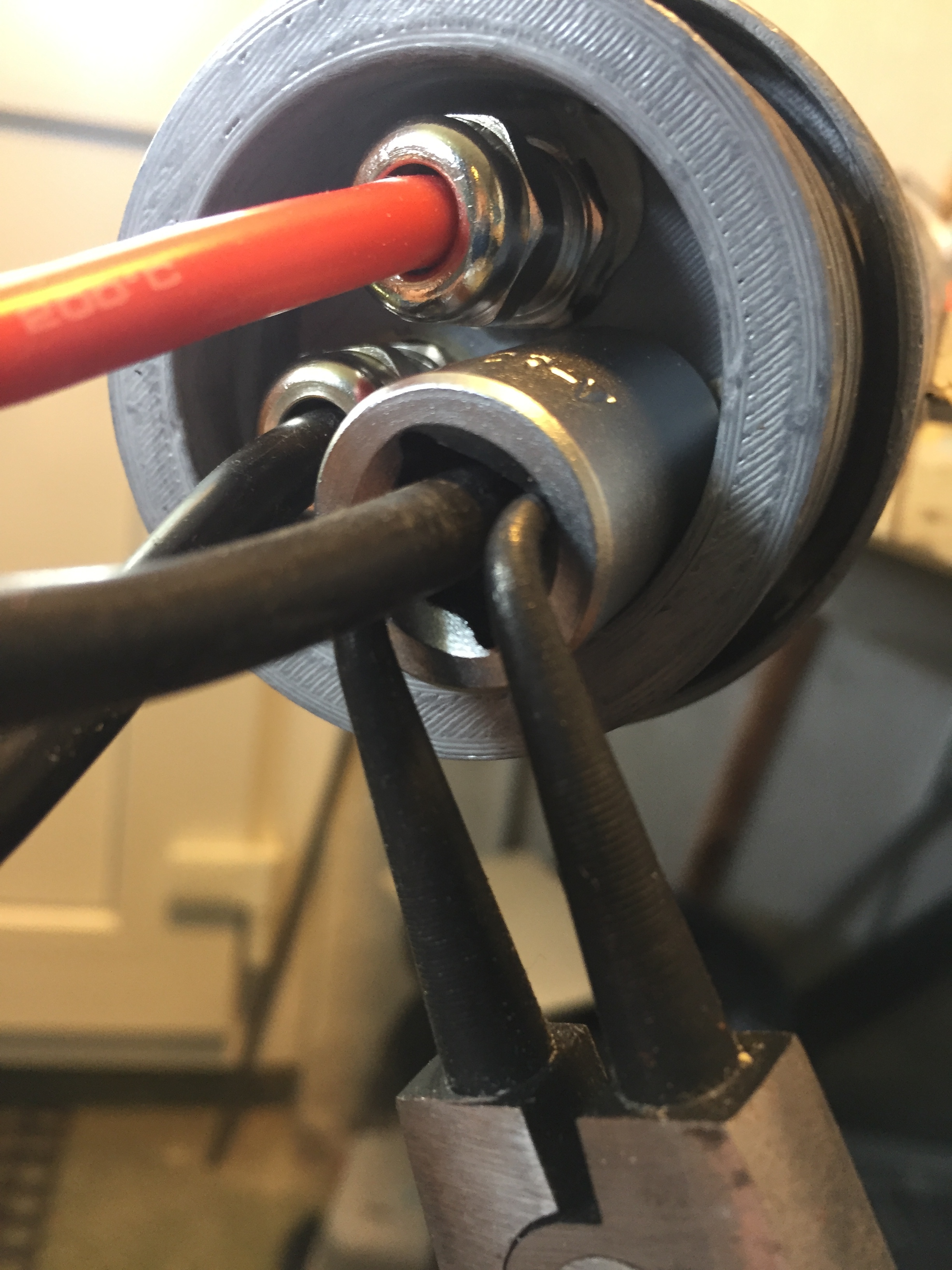
3d printed mast clamp with cable glands, thread is 3D printed an cut into the part. Part is coated with 2k polyurethane floor coating to waterproof. There are 2 rubber seals on both sides of the pod tube.
g)
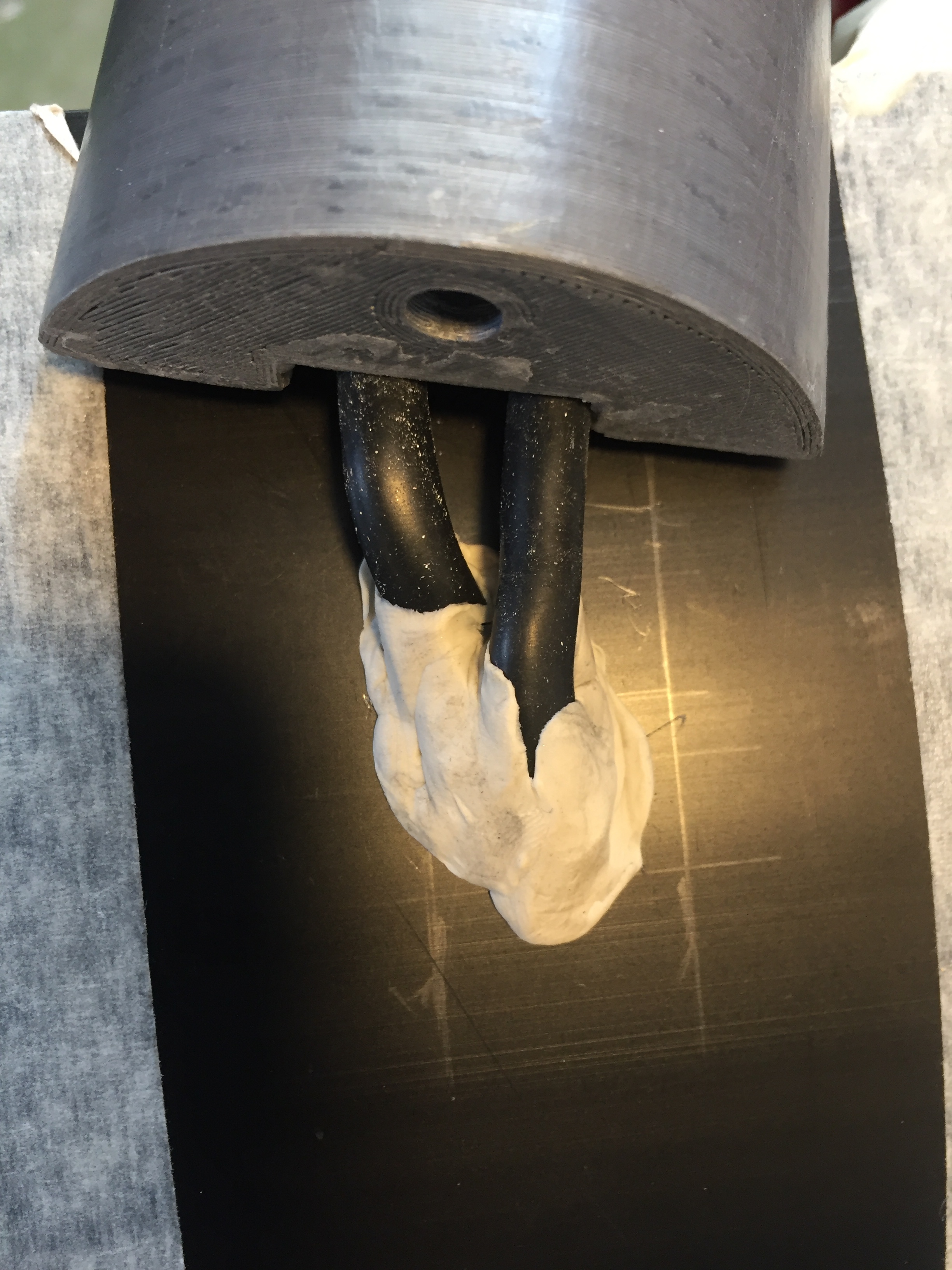
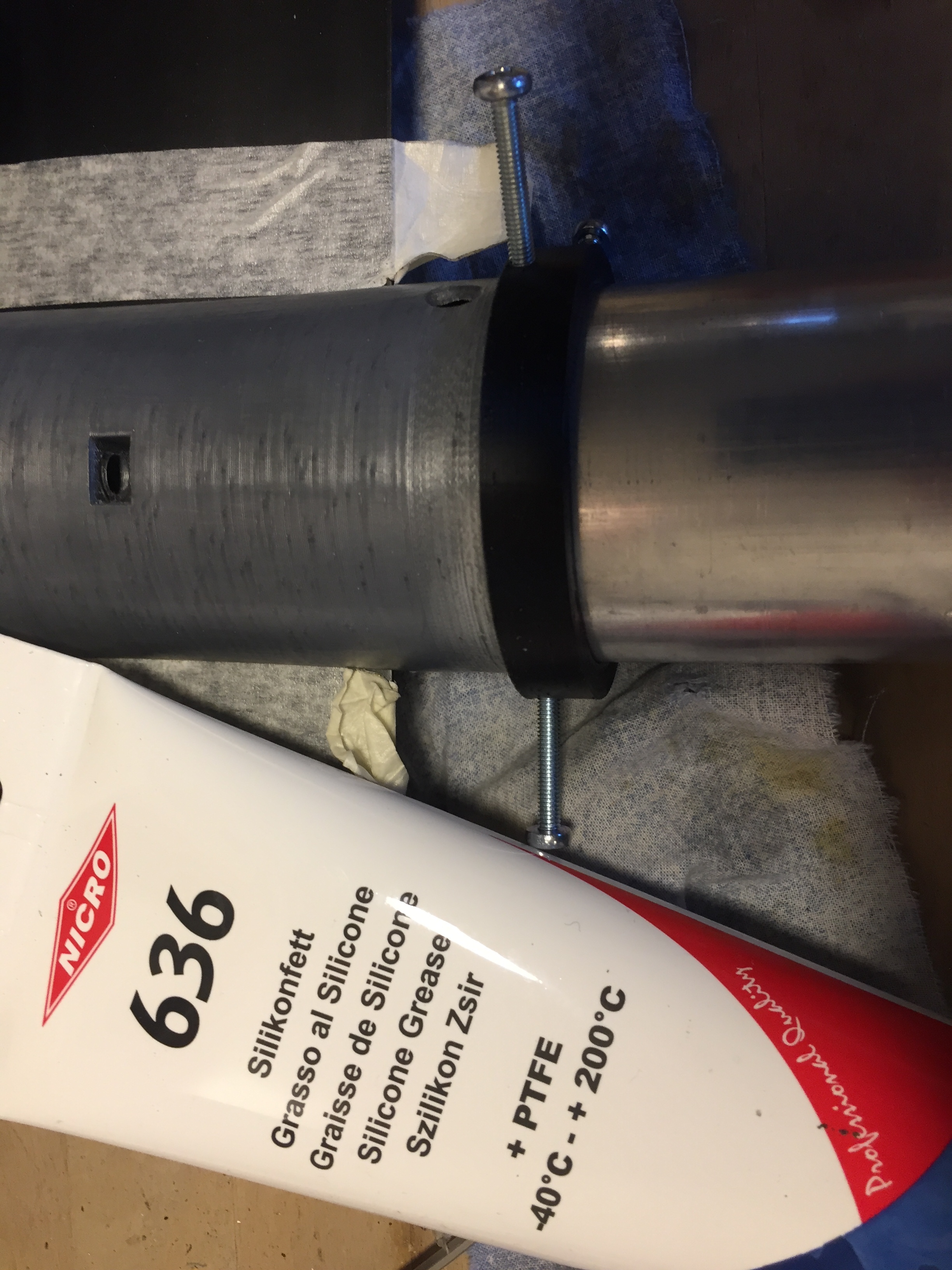
To prevent damage to the O-rings from the fixing holes in the tube while sliding the tube over, I built a tool with screws that fill the hole in the tube during the installation.
Inflatable board
Got this board from ali:
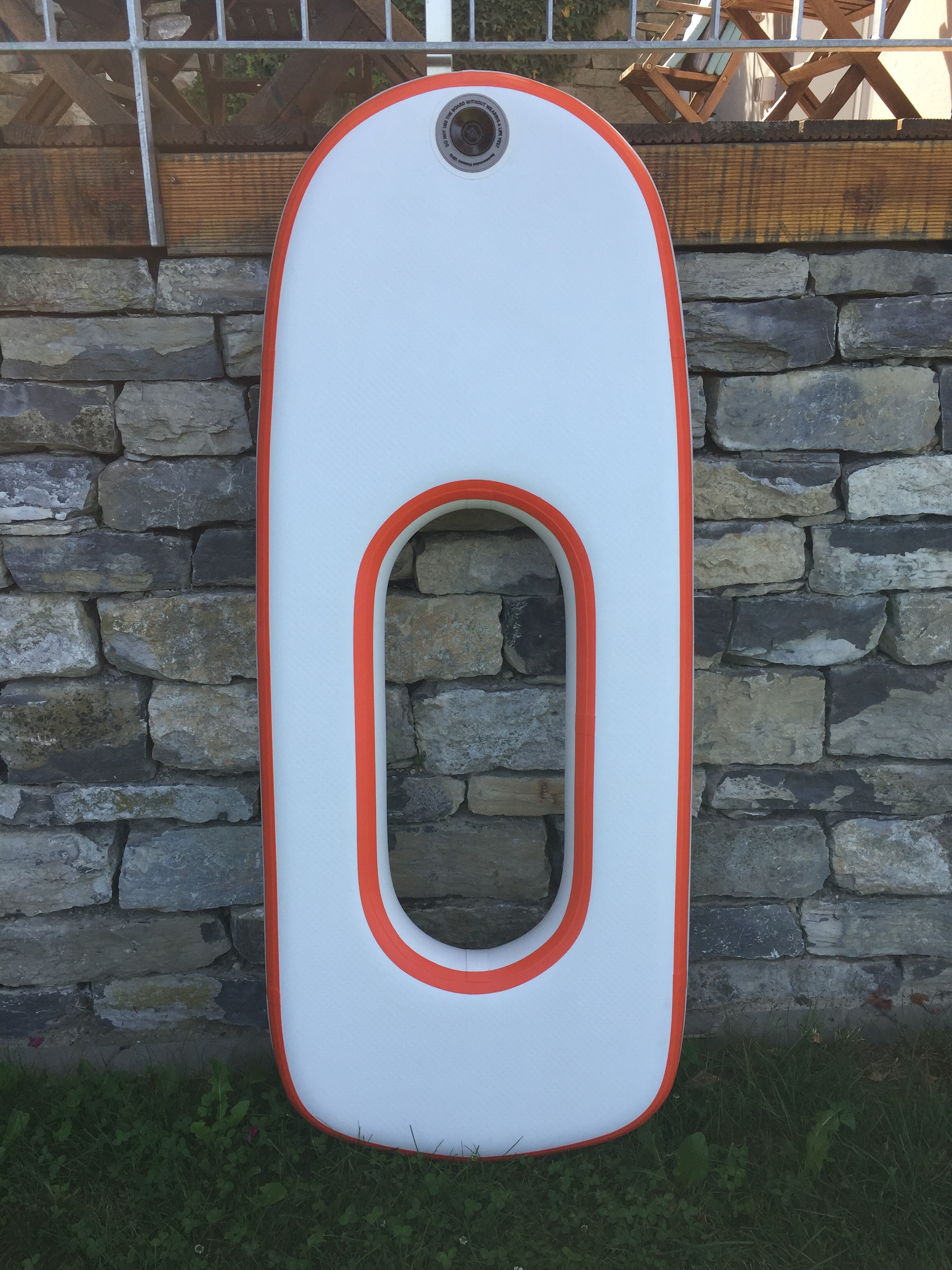
it ist 160x65x12cm, the opening is aprox. 70x30cm
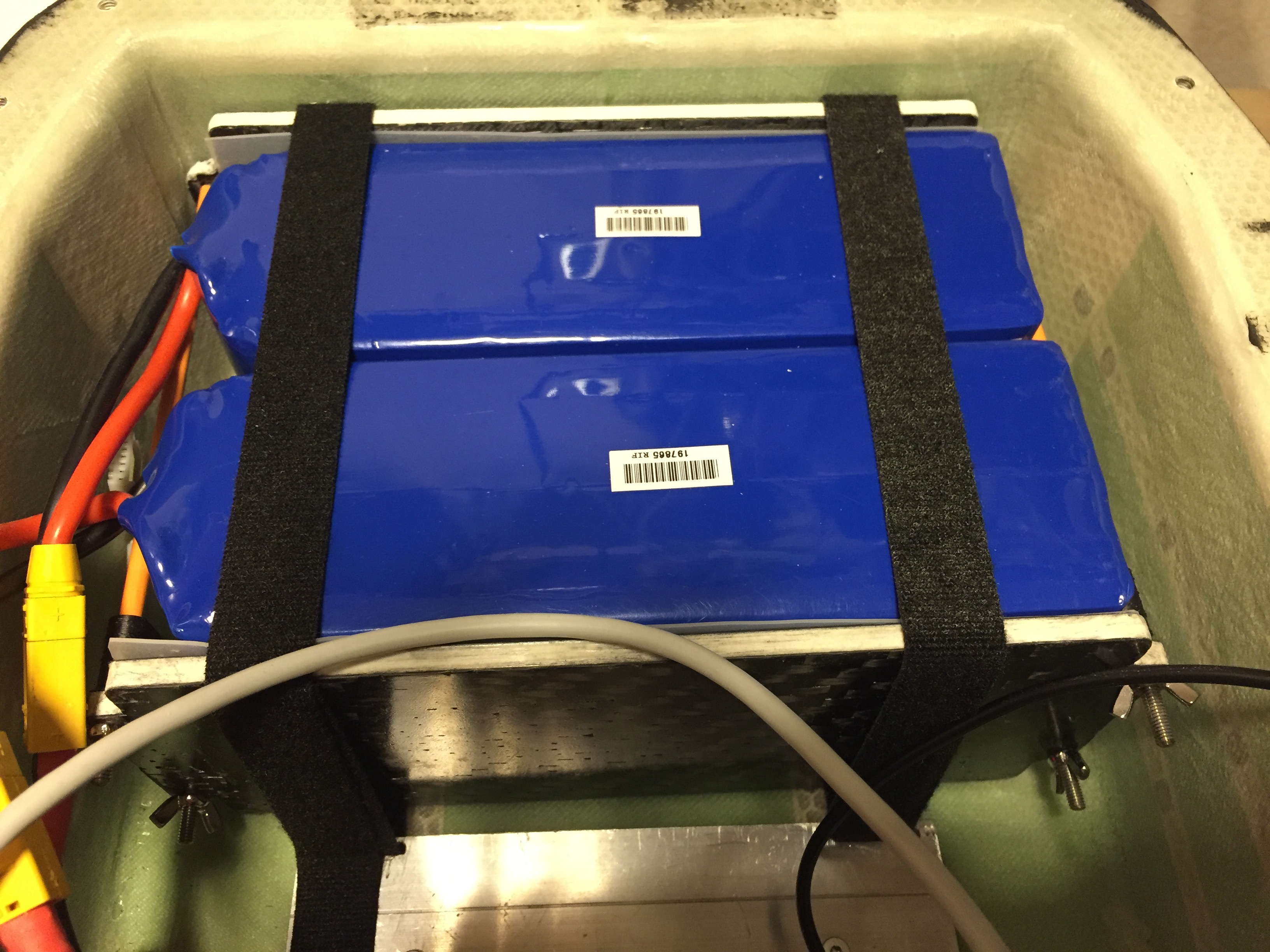
Electronics and battery box
It was not easy to build a box, first attempt failed as I missed the point that the hole in the board gets bigger when you inflate it.
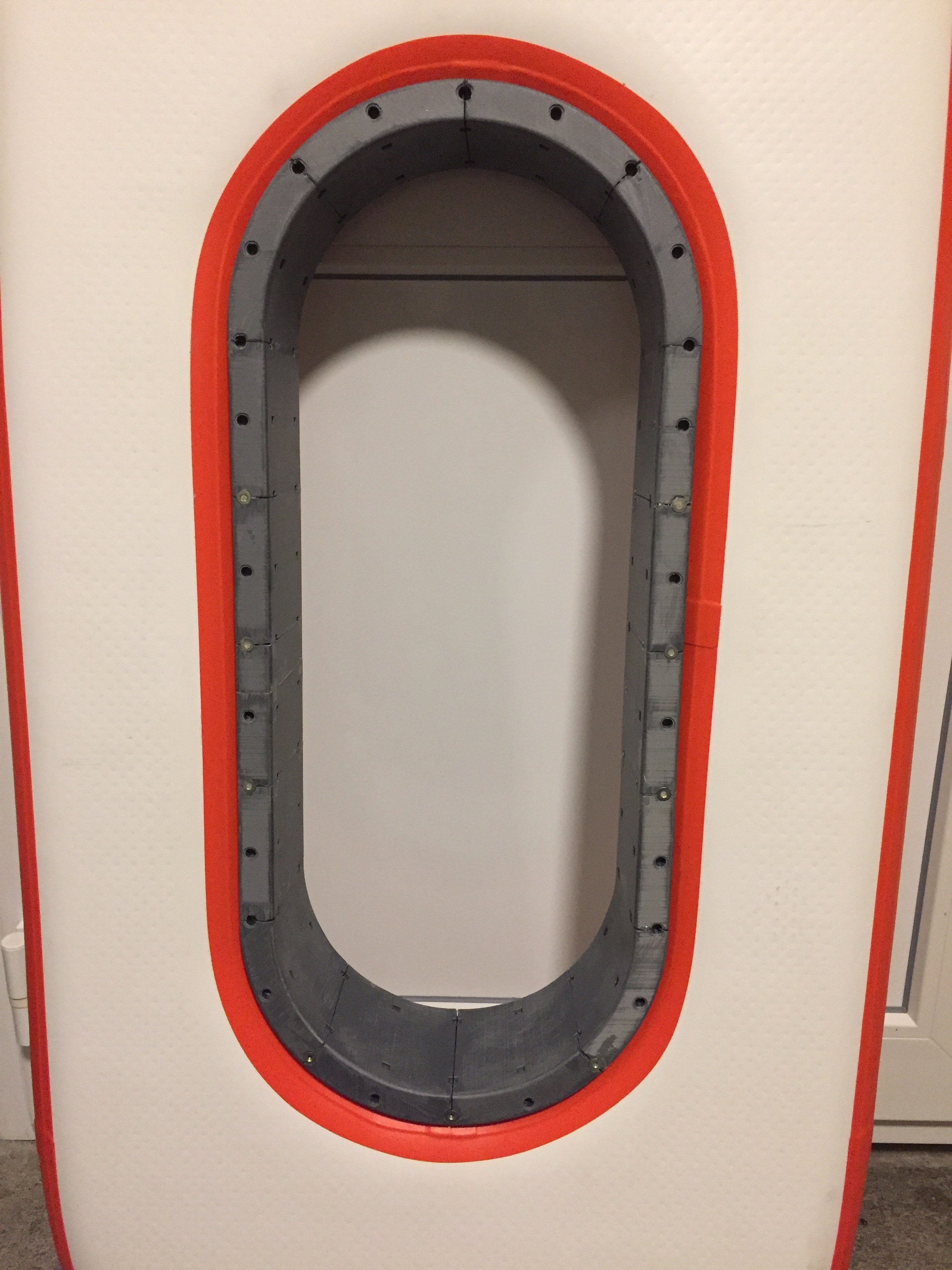
Fail! Can’t be put into the opening as one piece…
Next attempt worked out:
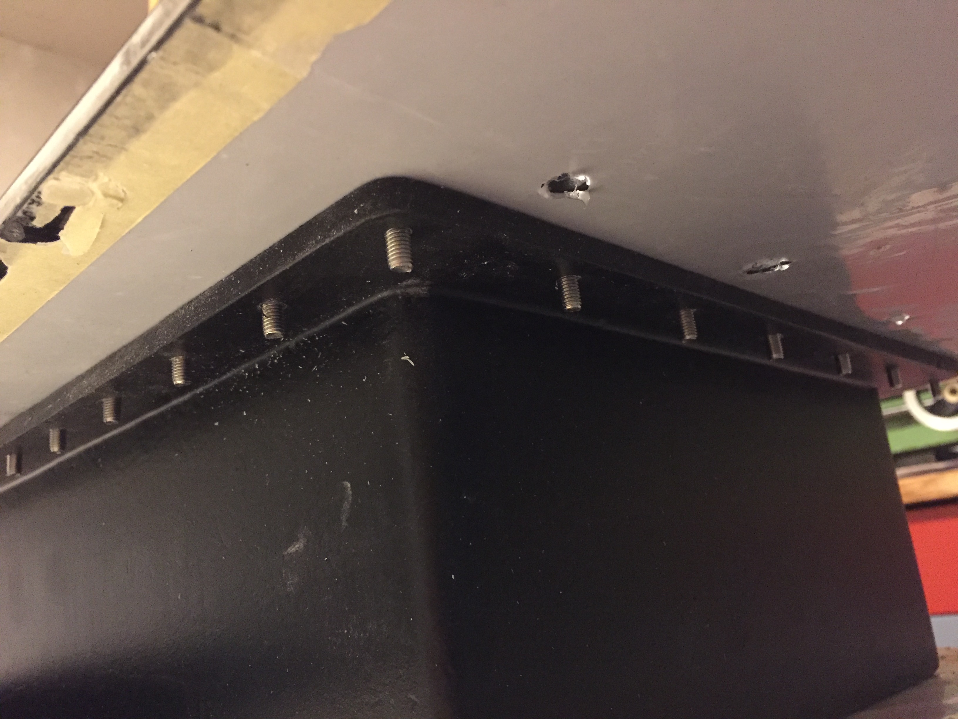
A box for the batteries and electronics, connected to a top plate that builds the lid, 8" hatch to access the batteries. separate ESC box in a wet area above the mast.

Mould from coated chip board and 3D printed parts.
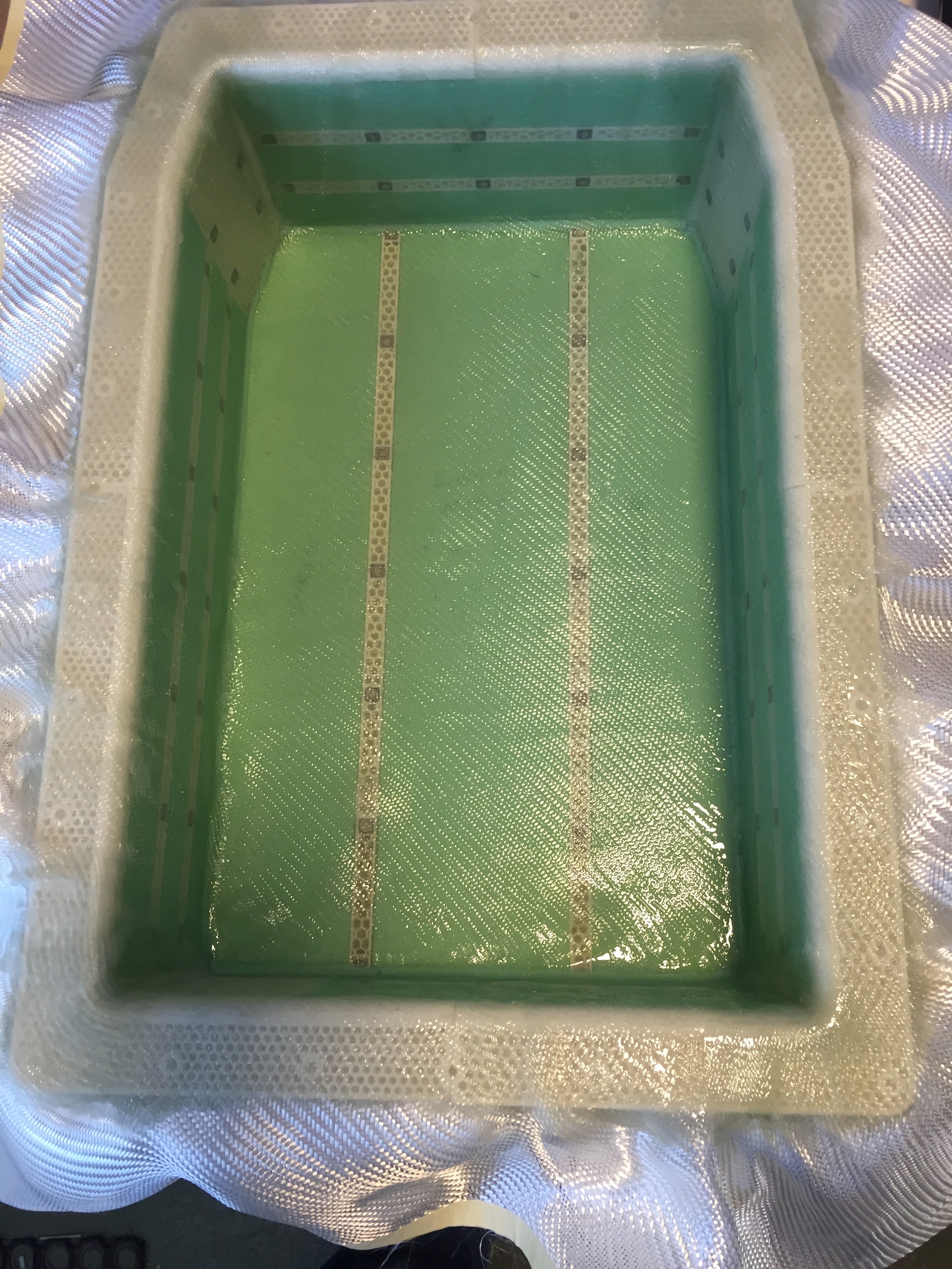
Fiberglass sandwich construction with 3 Layers of 280g fiberglass, 5mm sandwich core from foam and 3d printed parts, 3 layers on top.
M4 inserts to fix stuff inside. Inserts were hold in place with 3d printed rails. Threads were filled with “coltogum” seal and drilled out after curing (where needed).
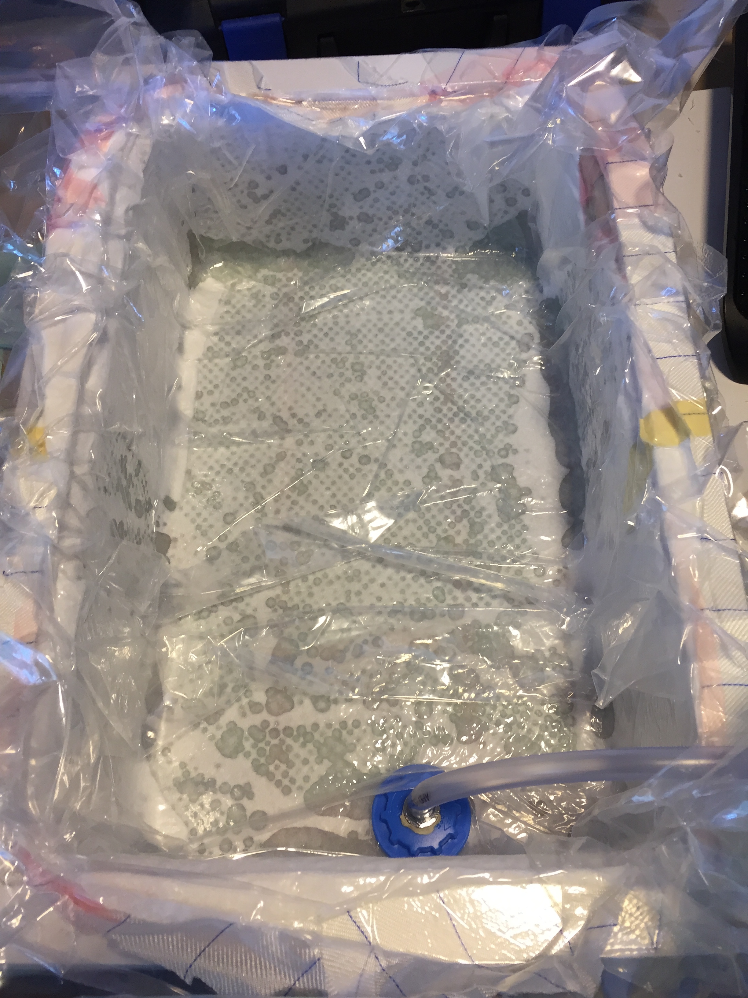
Vacuum bagging, at the top is a foamed PVC frame to get a flat and smooth surface (for proper sealing with the top plate).
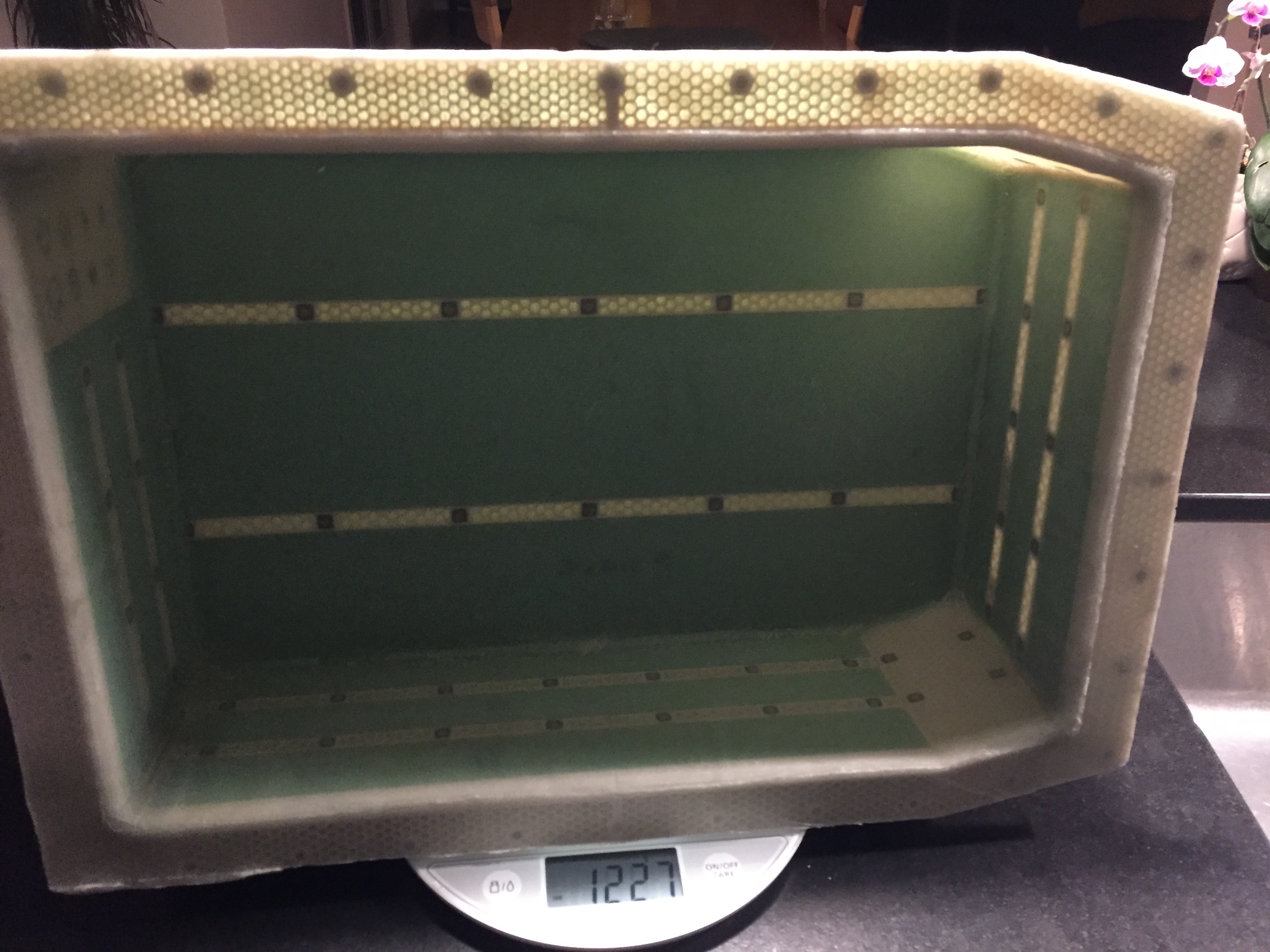
End result is a relatively light and stable box.
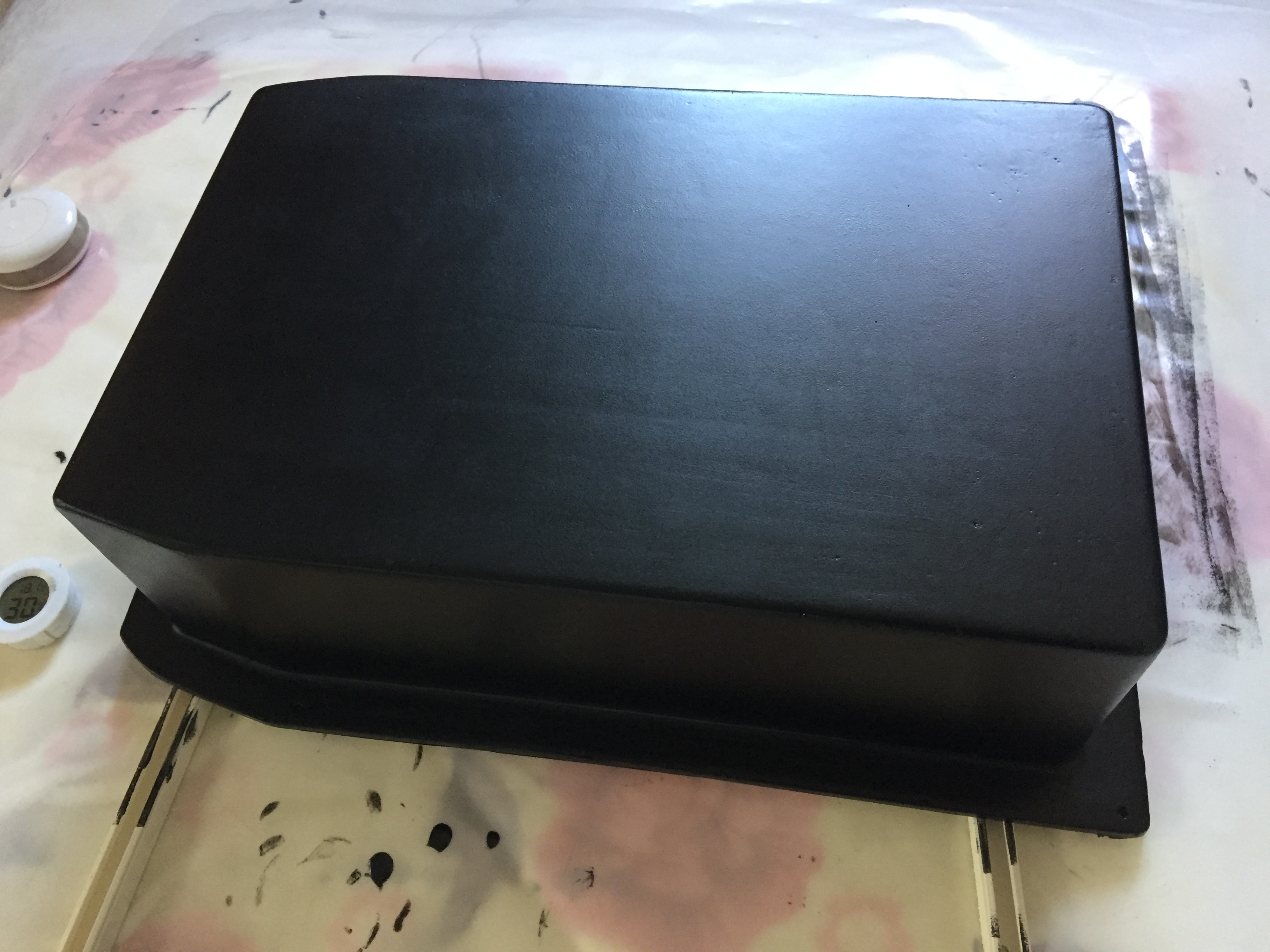
After some iterations of filling with epoxy filler and sanding, coated with pigmented 2k polyurethane floor coating:
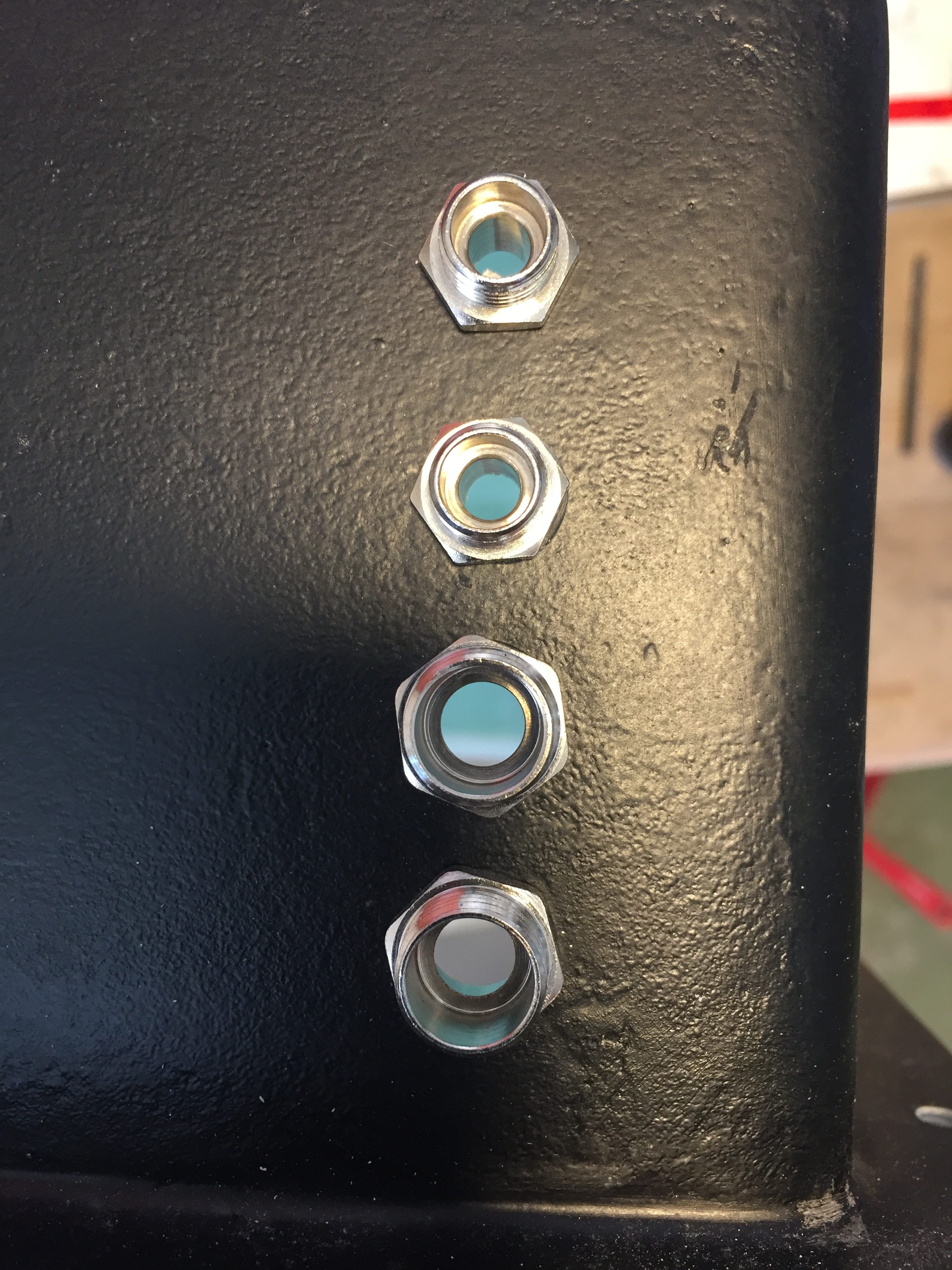
Cable glands screwed into 3D printed ASA-X insert with threads, which were glassed into the core of the sandwich.
Top and bottom plates
The idea was to build a CFK sandwhich for the top plate and a 2 part bottom plate consisting of a 4mm aluminium plate for the rear bottom part and a CFK board for the front. Top plate: 2 Layers of 400g CFK on each side, 5mm foam core, 3d printed edges and inserts, full 5mm CFK inserts for the spacers between top and bottom plates. 5mm acrylic glass window laminated into the sandwich. Wheight of the top plate is around 1.3kg which is ok but I think it could be built lighter and still be solid enough (the way I built the bottom plate with one layer of lighter CFK).
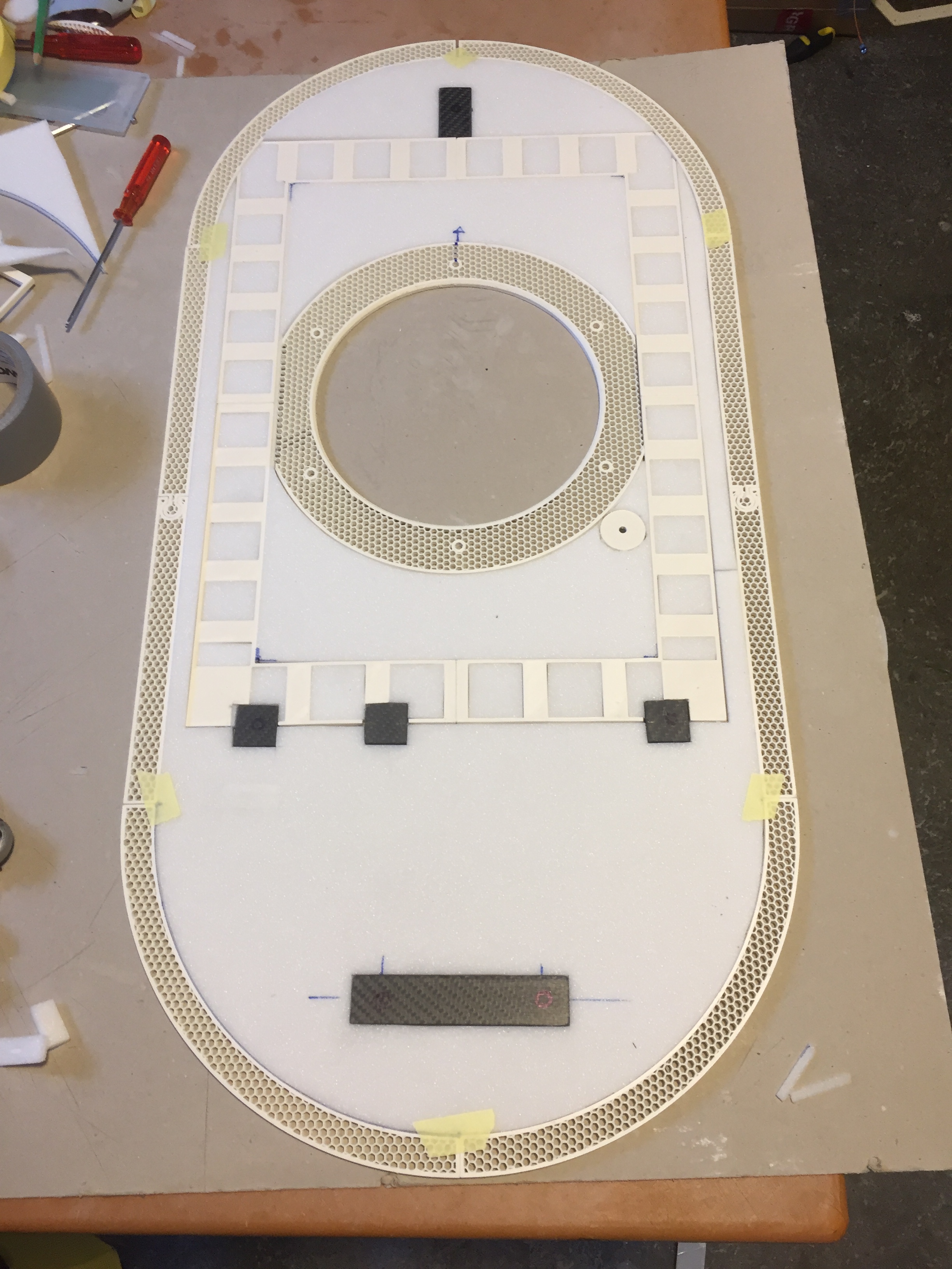
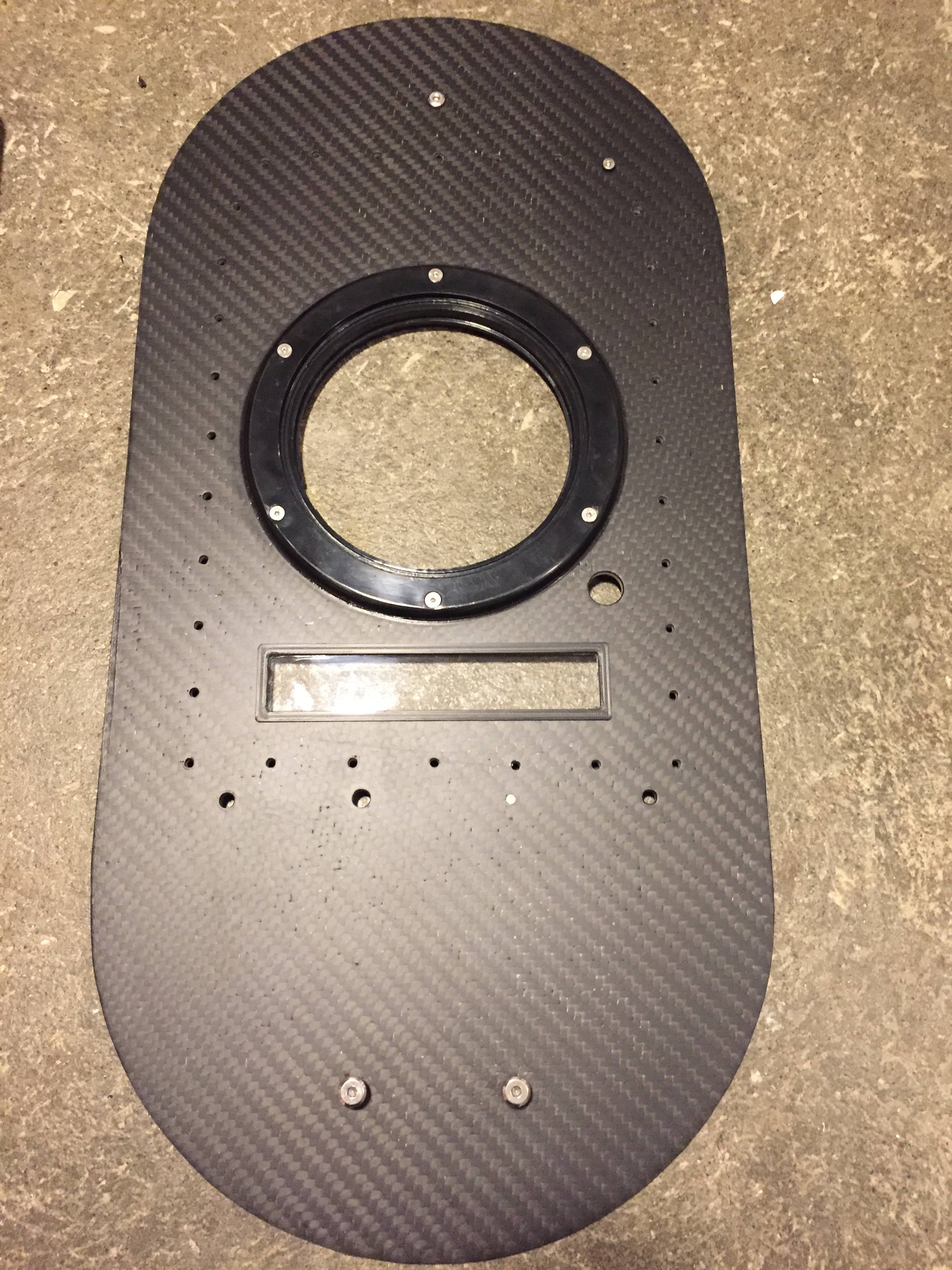
Acrylic glas window to see LED status and allow 2.4GHz signal to pass

Botom plate: lighter contruction with 5mm foam core, 1 layer CFK 400g/m2, 1 layer 160g/m2 and a light 80g/m2 fiberglass top layer. light and sturdy.
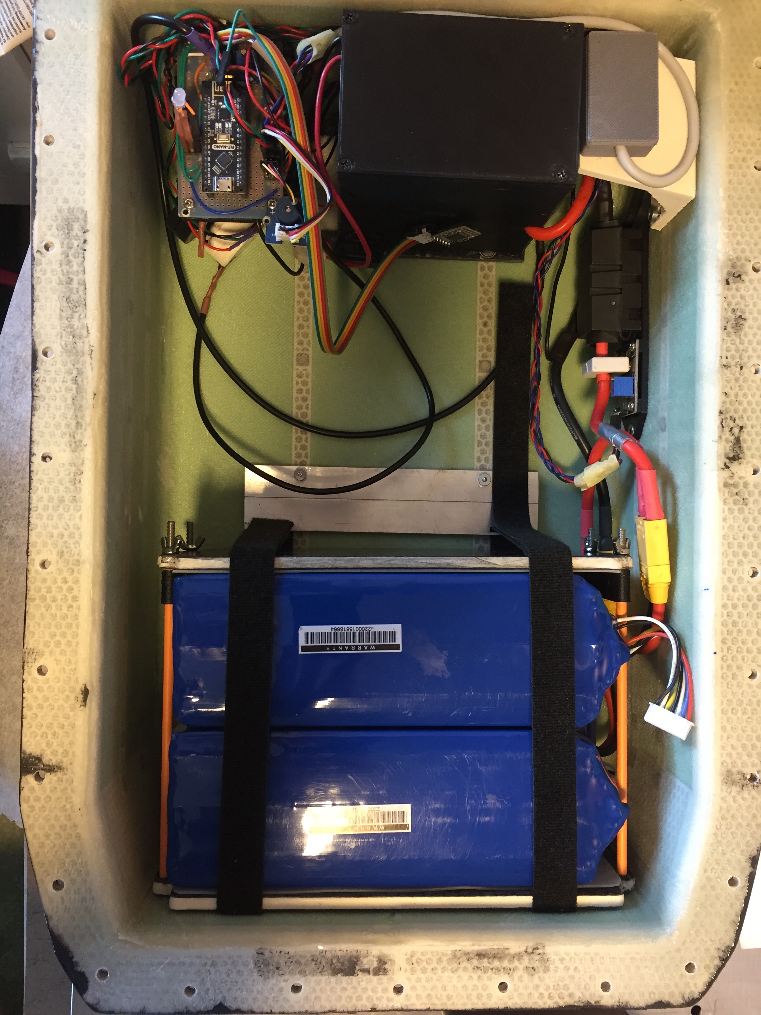
Electronics
Arduino nrf24 receiver, battery current hal sensor, GPS receiver (grey box) Dallas one wire Temp sensors for battery and ESC temp, water sensor with beeper and arduino logger There is also a magnetic lanyard safety magnet switch with a hal sensor, if the magnet plug is pulled out, throttle is set to zero. In the black box is a 100A contactor and an anti spark circuit with arduino and relays. After connecting the XT90 battery cables, power can be switched on/off
with an RF remote like a car key. This also servers as an emergency switch, if the magnetic lanyard shouldn’t work.
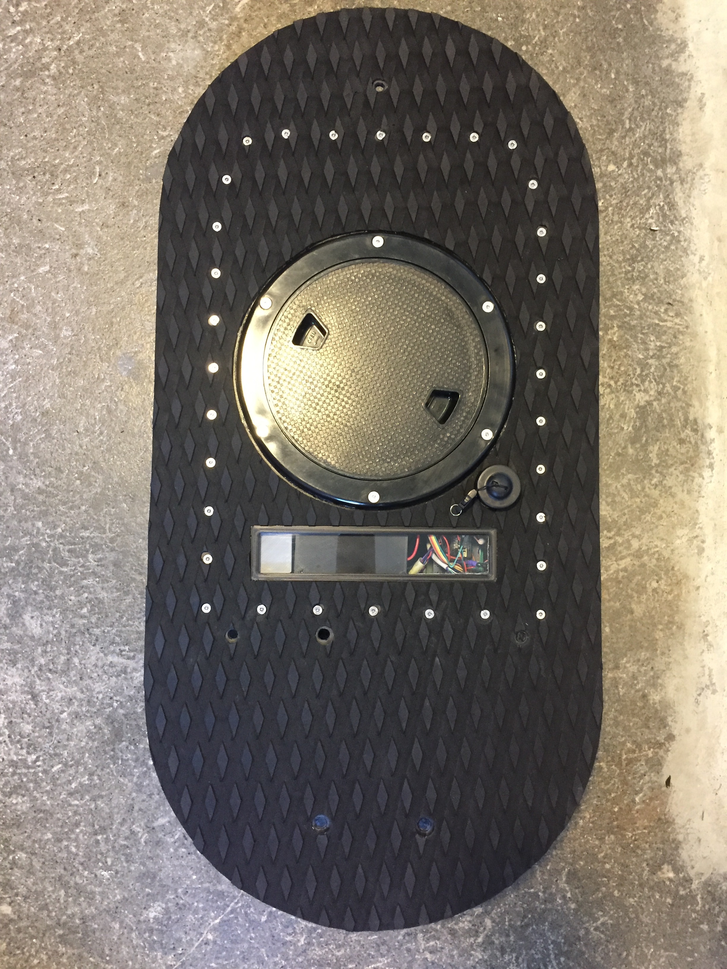

Lid lever to allow proper hatch sealing
Water test:


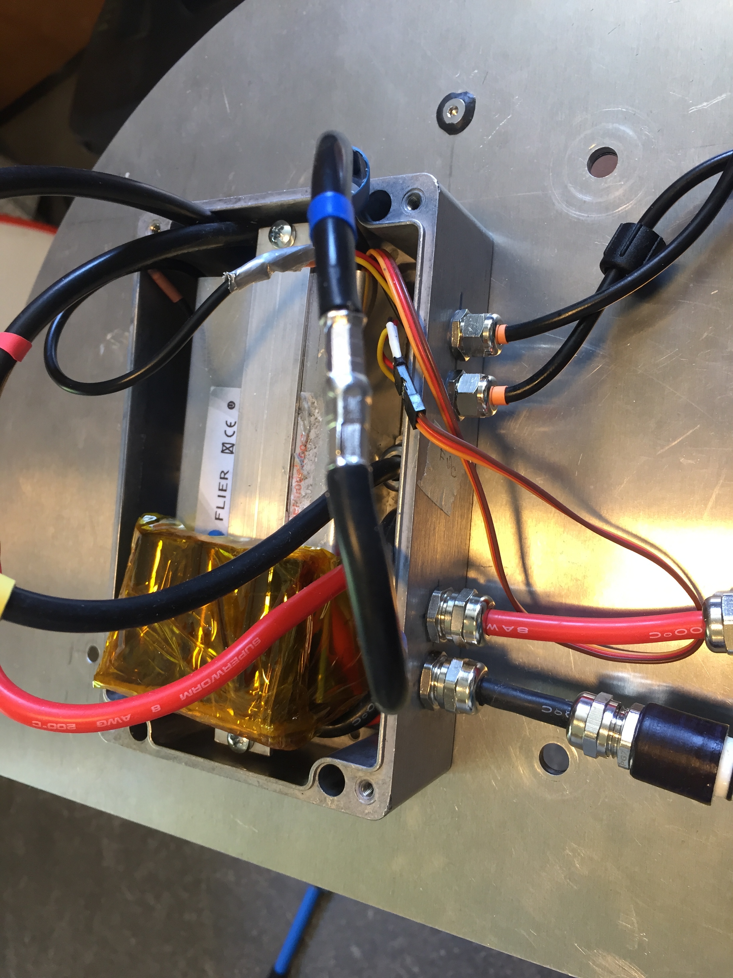
Flier ESC 240A 20S, passively cooled via alu housing and bottom plate, added some CorrosionX as @Flightjunkie suggested
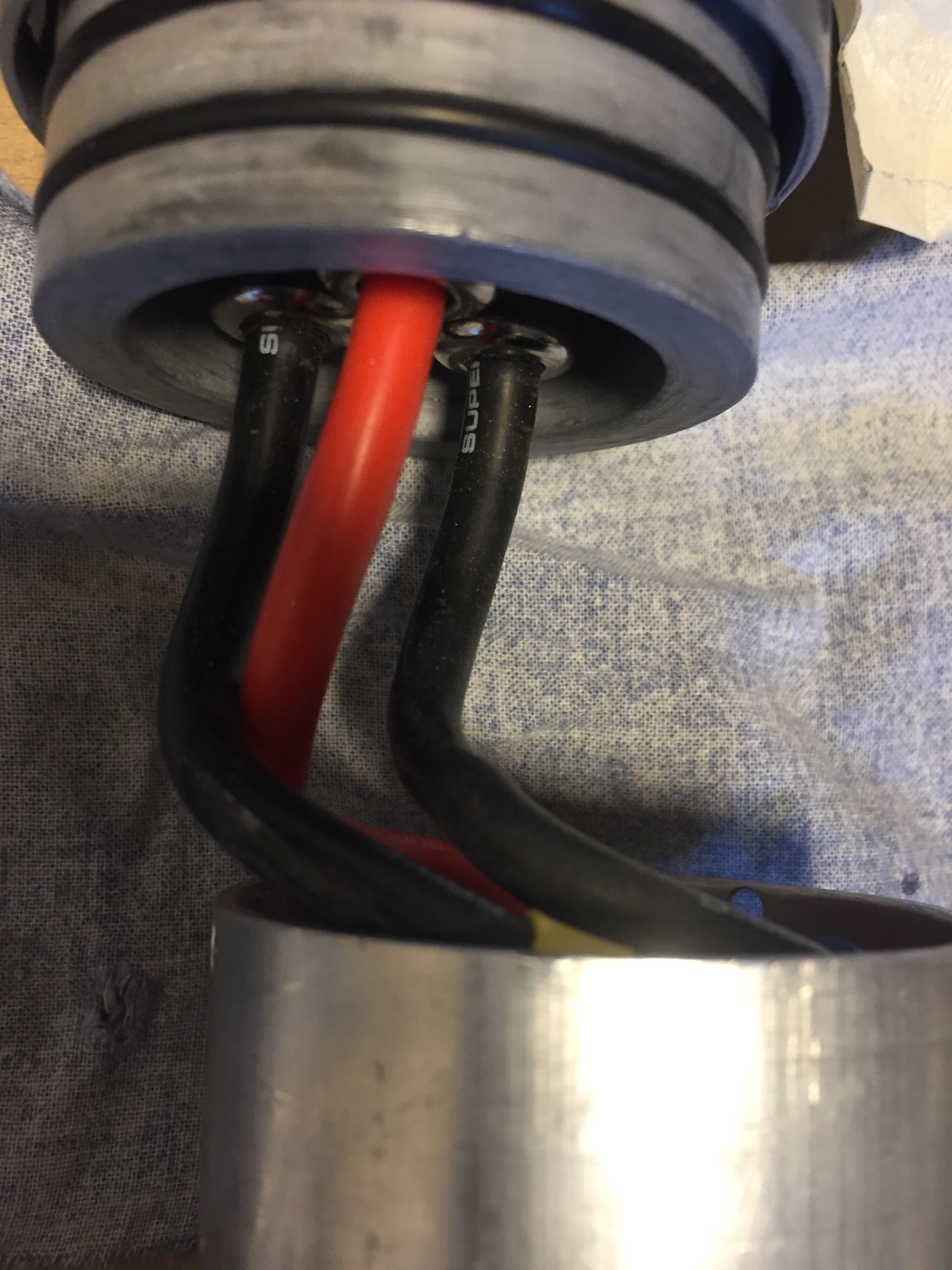
power connectors are 3D printed, pwm throttle signal and temp sensor cables are “waterprof” 3 pin LED connectors, they are available with up to 5 pins on ali (" Male to Female Connector Waterproof Cable for LED")
They are quite compact and with some silicon grease added they seem to be waterproof, just make sure they have o-rings on them, some mine came without.


Update1:
added some details