For my lipo i used 2 of ISDT : https://hobbyking.com/en_us/isdt-t6-lite-600w-charger.html with 2 power supply 20A 12v
Worked very well ( balancing is not extremely precis but it was fine ) since i have them , for my 18650 i slipt it in 2x6s
ISDT have also a 8s
1 Like
Hot wire cutter is complete and works. My bench power supply only delivers 5A so it barely has enough power to get the wire through the foam but if I go slow enough it works fine (you can see the test cut in the foam block)
So Basically what you’re looking at is a 20AWG nichrome wire loop, 2 heat insulation screwterm blocks, then behind them those 2 little blue wires are high-temp wire which comes off the nichrome and attaches to standard 18AWG wire (OR/GN). All installed on a nice piece of oak.
I’m weighing the option of getting a bigger supply or just calling it good enough. I rarely call things good enough when the alternative involves acquiring giant prehistoric rheostats, but this time I might have to resist, since the clock is ticking.
1 Like
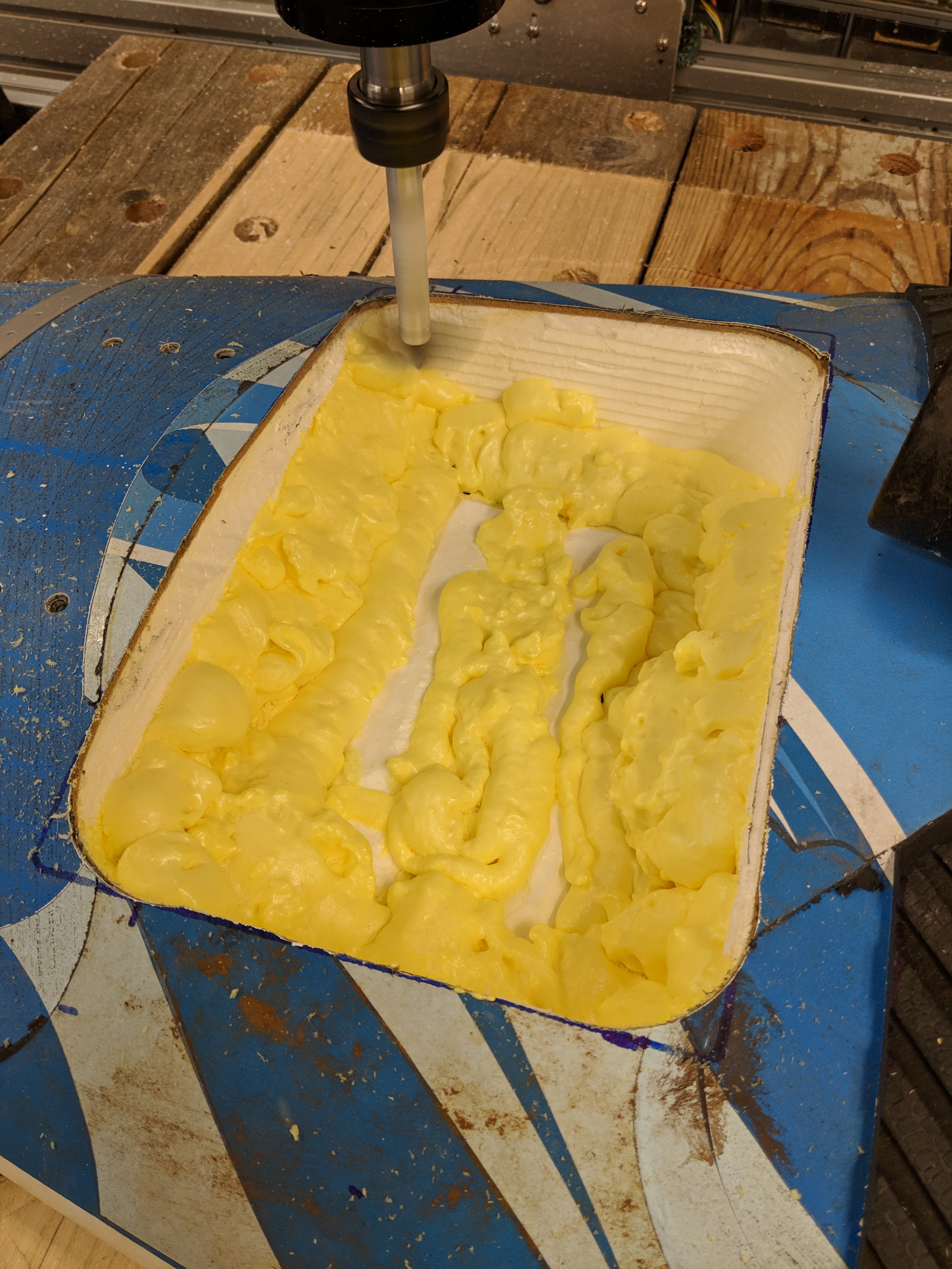
Well, I screwed up a couple of minor things. The hot wire scooper worked well except for the aforementioned lack of current from my power supply, but a bit of patience and i was able to scoop the foam out.
Unfortunately in a few spots I accidentally scooped up under the edge of the cutout. I didn’t think this was a big deal - I’d just fill it in with spray-foam and re-shape it, but it turns out that despite the similarity in names styrofoam and sprayfoam do not get along. In fact they darn near repel each-other.
So now I need to figure out how to fill the voids back in.
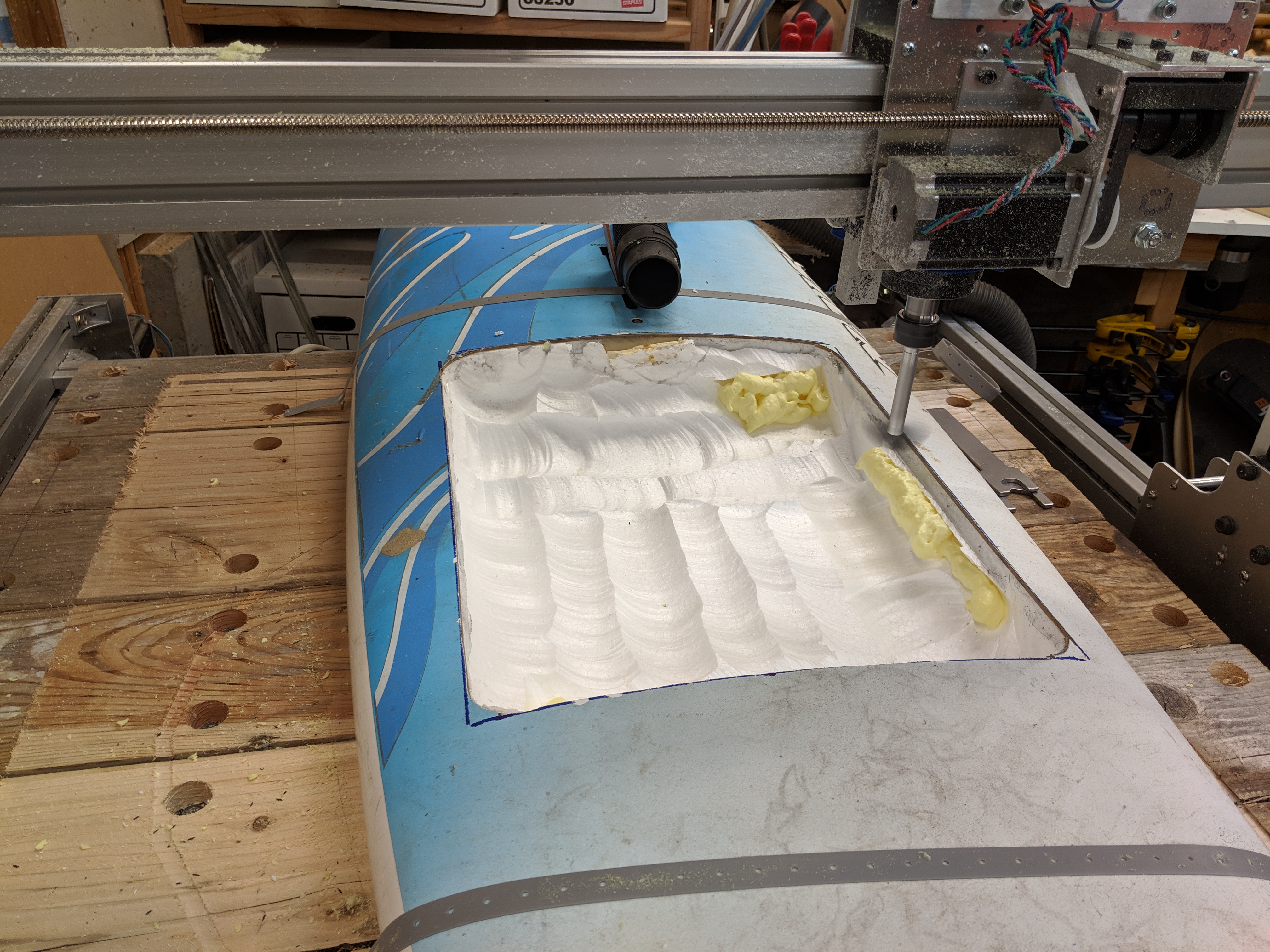
I had known all along that I wasn’t going to be able to get the base flat and the edges as clean as I wanted with the scooper alone, so I went back to my wildly dangerous home-made router bit. First I determined the edges of the board, then I made a little model that would cut down all four sides and then plane across the bottom resulting in a nice clean opening.
Here are a couple of videos of the carving in process.
It did work, except I screwed up and made it too deep and it started to cut into the bottom fiberglass. Fortunately I was able to stop it before it did any real damage.
oops.
I have to say, the CNC thing worked really well. If I had a real dust collection system I could definitely have skipped the hot wire process. As you can see from the vid it was snowing pretty heavily - and that’s with the shop vac on and attached.
So the first job ahead of me is to figure out how to re-fill parts of the cavity with styrofoam, and then go back in and carve a nice clean opening for the fiberglass.
The second job has to do with charging. I went ahead and got the iSDT D2 and it does work, but it is really sensitive about connections between the two sub-packs. Even having a little volt meter bridge the two causes it to start flashing warnings.
Let me go back for a second and explain what I had planned to do. I’m running 12S9P and I was going to have the cutoff split the pack into 2@ 6S sets. Then the two halves of the D2 would be able to charge both half-packs at the same time. I tested this on an esk8 and it works fine so long as there is no connection between the packs. But if anything bridges them, as I said above, it doesn’t work. This means that I have to disconnect the ESC if I want to charge which isn’t a good option.
One of the things that I omitted in my electrical master plan was a fuse. So I’m going to add a fuse to with the line going out to the ESC, but since I don’t want to have to pull the fuse itself to charge the pack I’m going to make a board that contains both the fuse and a loop key. That way I pop the cutoff, pull the loop key and then the 2 packs are completely isolated and the D2 won’t whine so much.
I hope.
2 Likes
The good news is I was wrong - spray foam does stick to styrofoam. I think after it’s initially sprayed on it bubbles down into the foam bit and the chemically bit and the chemical bit actually does stick to styrofoam.
So before:
and after:
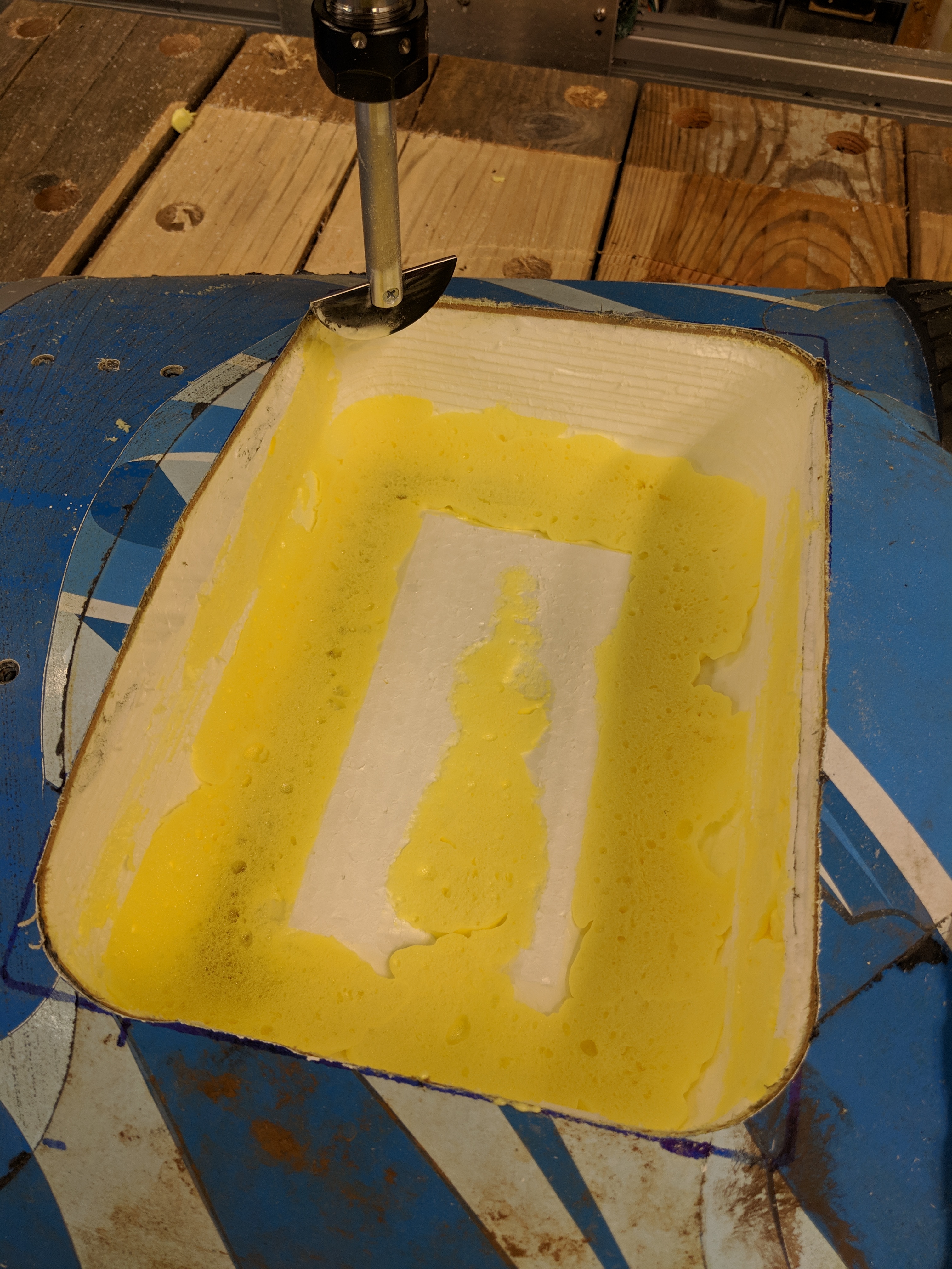
I re-foamed in a few gaps and holes since it’s only Thursday; and am going to CNC it again this weekend, as well as CNC the battery compartment.
Also I might try to improve on the router blade - if it were more U shaped and less D shaped then I wouldn’t get those ridges you can see in the sidewalls. I made it out of an old table saw blade so pretty easy to make another one.
Quick update, a couple of posts ago I talked about adding a fuse and a cutoff Loop Key - I was going to make a PCB that contained these two items. The purpose was to be able to absolutely isolate the 12S pack into 2@ 6S so I could charge simultaneously.
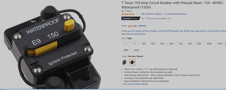
Turns out the boating community has exactly this in a single super-handy device:
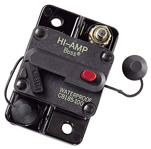
I don’t know why it didn’t occur to me before. Size is likely to be an issue - I may have to move things around in the battery box.
Anyway it’s on order. Today I’m carving up the battery box compartment.
I have the same breaker rated 150A. Still have to check if that’s sufficient for my 56104/kV650/12S jet setup.
I used the same one ( be carefull the quality Ones are not in plastic but “Bakélite”) in between my 4s pack to get 8s when switch on , worked well all last summer ,got the 200a , will still use it this year , but it gets a bit warm/hot after a long run
That is a way to keep the 6+6 for charging but 2 plugs will be left alone when running i didn’t like this idea …
@ Kappertz, @ Alexandre sounds like I might be under-amped. I haven’t ordered it yet - might bump up to 150A.
Thanks!
Last year I used this one. I am no longer using it. These are my observations. Many people on this forum are using it. It takes up too much space to fit in my enclosure. Never tripped even when I got in weeds which caused me to destroy my 200 AMP ESC. The XT90 connectors on my pair of multistar 20Ahr batteries started to melt first. I read somewhere that you need to go over 150 AMPs for quite while for it to trip. It works fine for a ON/OFF switch with no additional anti spark. Feels and looks high quality.
1 Like
MAC you are correct it only trips-out after a long time ,its good to highlight this.
See trip time vs rated current.

Shoulda stuck with the 80A 
I only expect this to work for catastrophic failures (dead shorts) but this is good to know - the one I got is unlikely to ever trip. When it gets here I’ll check the size and see if I can use it at all, then swap it for a smaller one.
If I blow up my driver I’ll probably replace it with a VESC6 since it’s a lot more configurable. However it tops out at 100A. Come to think of it I better start logging current draw (scope creep!).
Thanks for the input.
Maybe consider some of the designs based on the Vesc6 that run the same firmware if you choose to go this route. I only have experience with my diy vesc, but there are several to choose if you search the electric skateboard designs. E.g. A200S, there are also some ready to purchase with similar price.
1 Like
@Flo thanks for the guidance - the A200S sounds like the perfect project for the fall…
When you say diy vesc did you design one from the ground up? You don’t happen to have a build log for that do you?
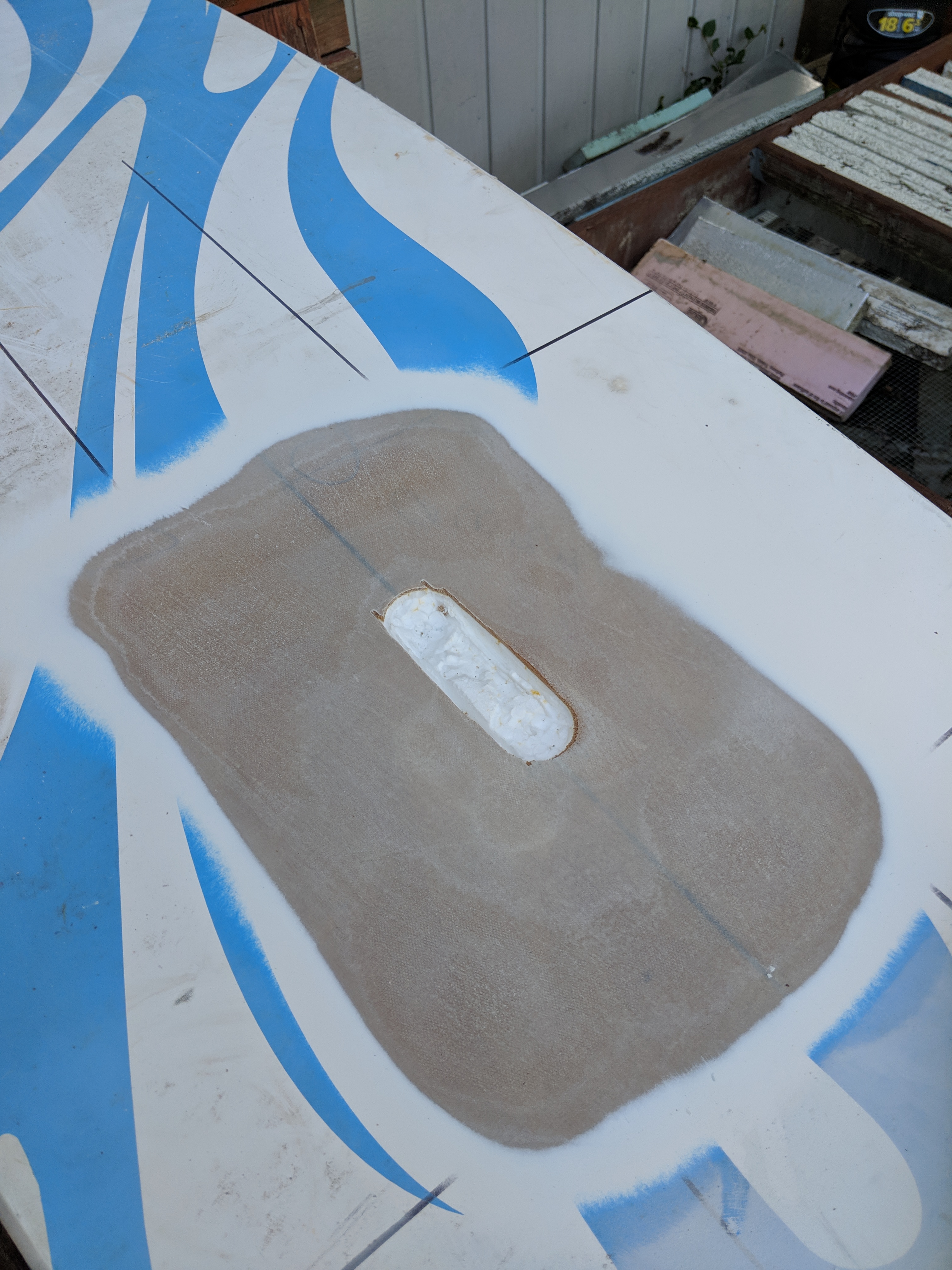
Ok, after 2 runs I got the battery box cutout cleaned out.

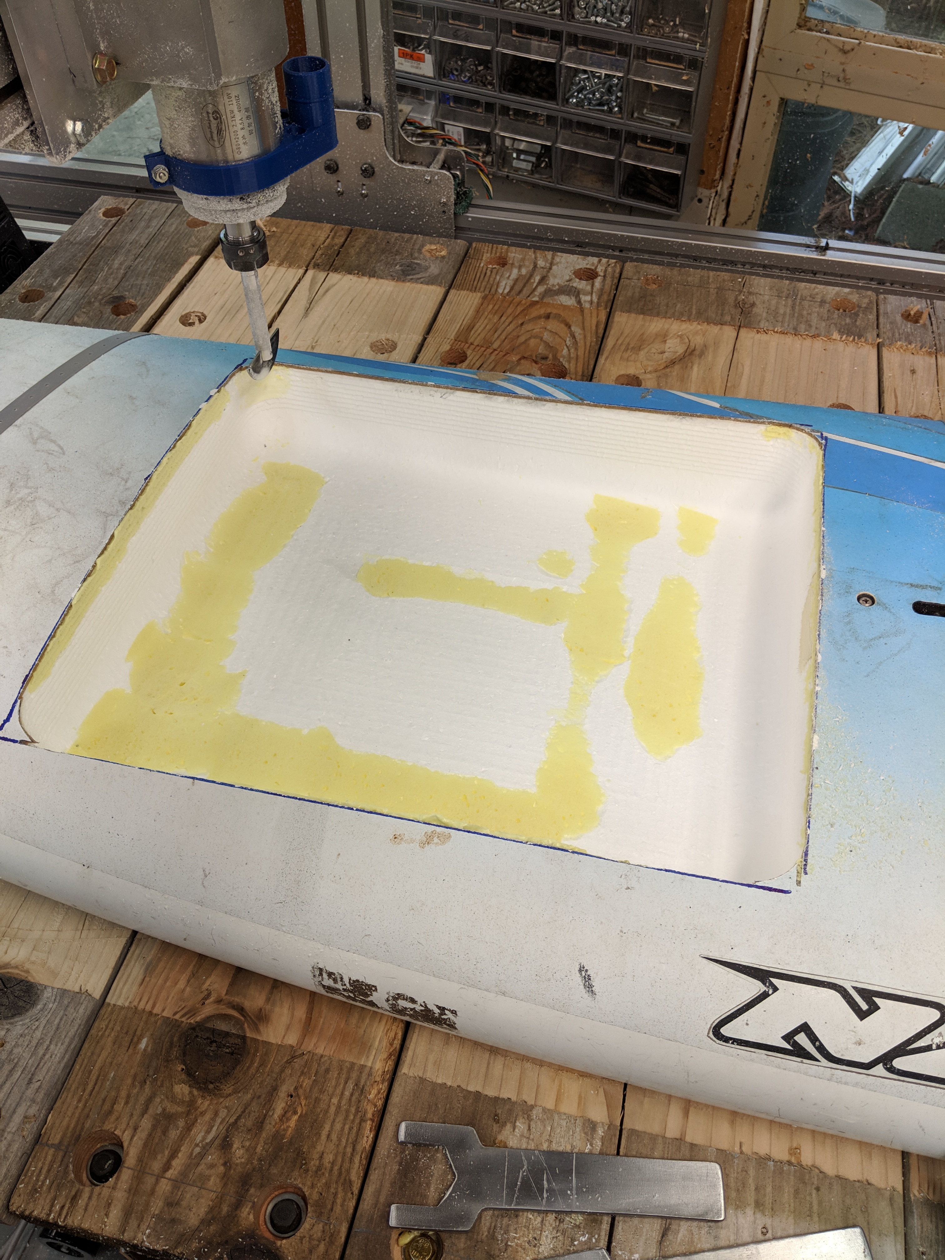
I did learn the wisdom of rough cutting vs. fine cutting. My original plan was 0.2" depth cuts with 0.3" stepover. If I had done that the thing would still be cutting. I roughed it out with 1" stepover and then went back and did a 0.3 stepover final.
I just need to router around the outside edges to give myself a roundover, then drill some drain holes and start drilling sideways to run lines between the battery box and the power box and the mast. So I guess the next step is to place the mast mount.
Then fiberglass these two openings in.
I liked @MAC’s idea of getting a big water trough for testing. I was originally going to just take it down to the lake and go for it, but I can see the wisdom of doing some actual load testing before committing to a large body of water.
Heading out to the Issaquah Grange tonight!
on top of looking at the amp, the voltage you’re using and the quality of your connection will matter a lot:
i started using that:
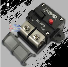
but it kept tripping, and to turn it back on you have to open the board on the water… and if you let a few drops in at the wrong place, you coulomb meter will literally take on fire…
now i’m using:
171-S1-200-2
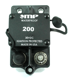
and not a single issue, and even if it trips, it should auto-reset.
The difference was that the first one was rated for 12V and the second one is for 48V.
On top of that, it was much harder to get good connection for the wires in the first one, and i’m guessing the reduced area of contact made it heat even more.
I think in the end, it was never tripping due to high current, only due to heating up too much…
On the second one, you just solder ring terminal and the connection is much better.
1 Like
Same here. The nuts need to be very tight or it will heat up a lot. I could smell the heat coming off the nut on my relay. Just had to touch it anyways. My finger made a sss noise.
A bit of forward movement, I got the edges of the cutouts rounded over and sanded down to the fiberglass around them. I figured out how I’m going to route the wires from one place to another, and I made the mount plate for the mast.
(If you look closely you can see where I screwed up the center when I started the cut on the CNC machine, but it doesn’t hurt anything)
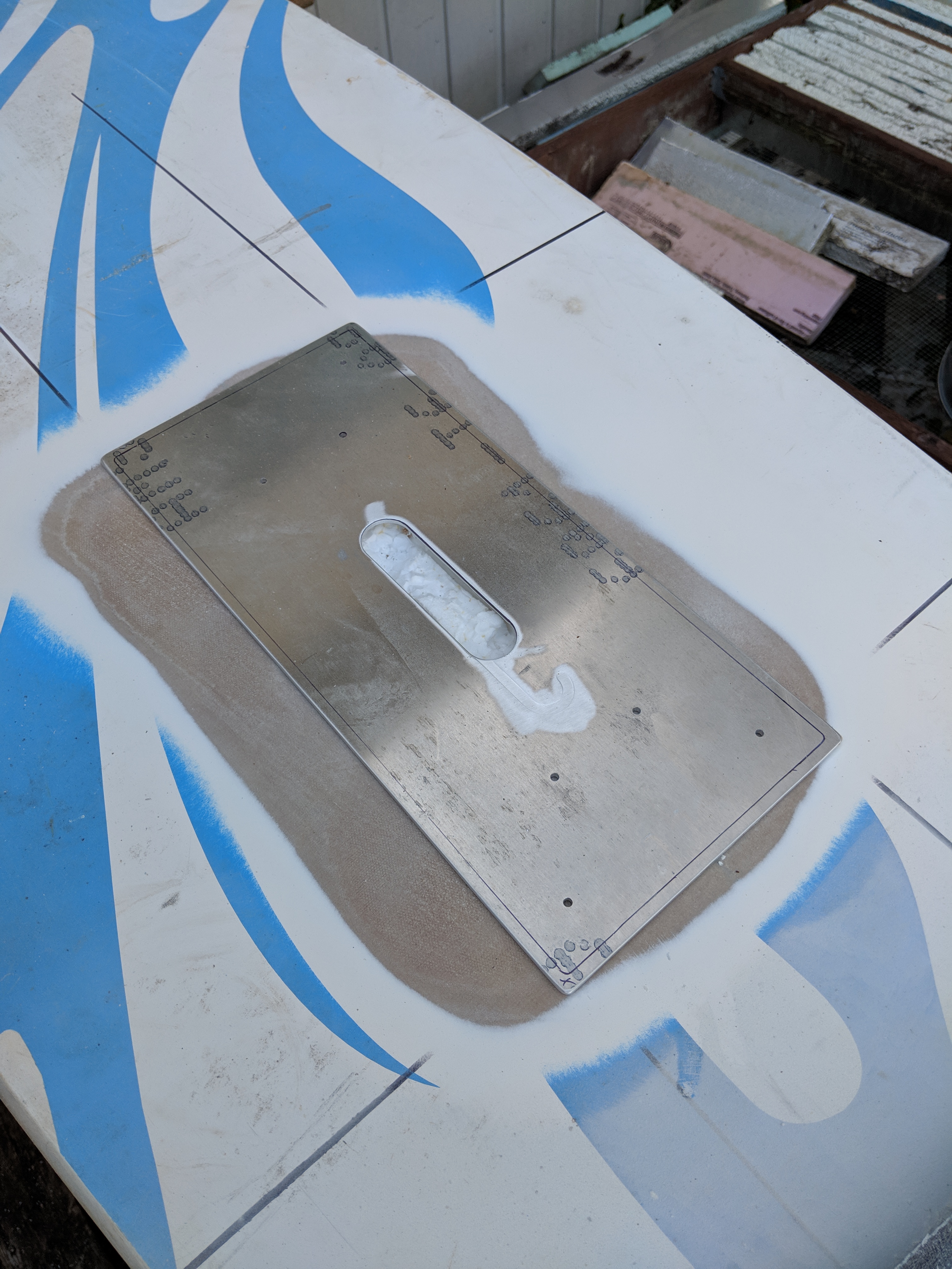
Those tiny holes will get drilled out and threaded inserts will be pressed in, then the whole thing will be epoxied in place.
Also, following in @Mat’s footsteps I got a Stock Tank for testing.
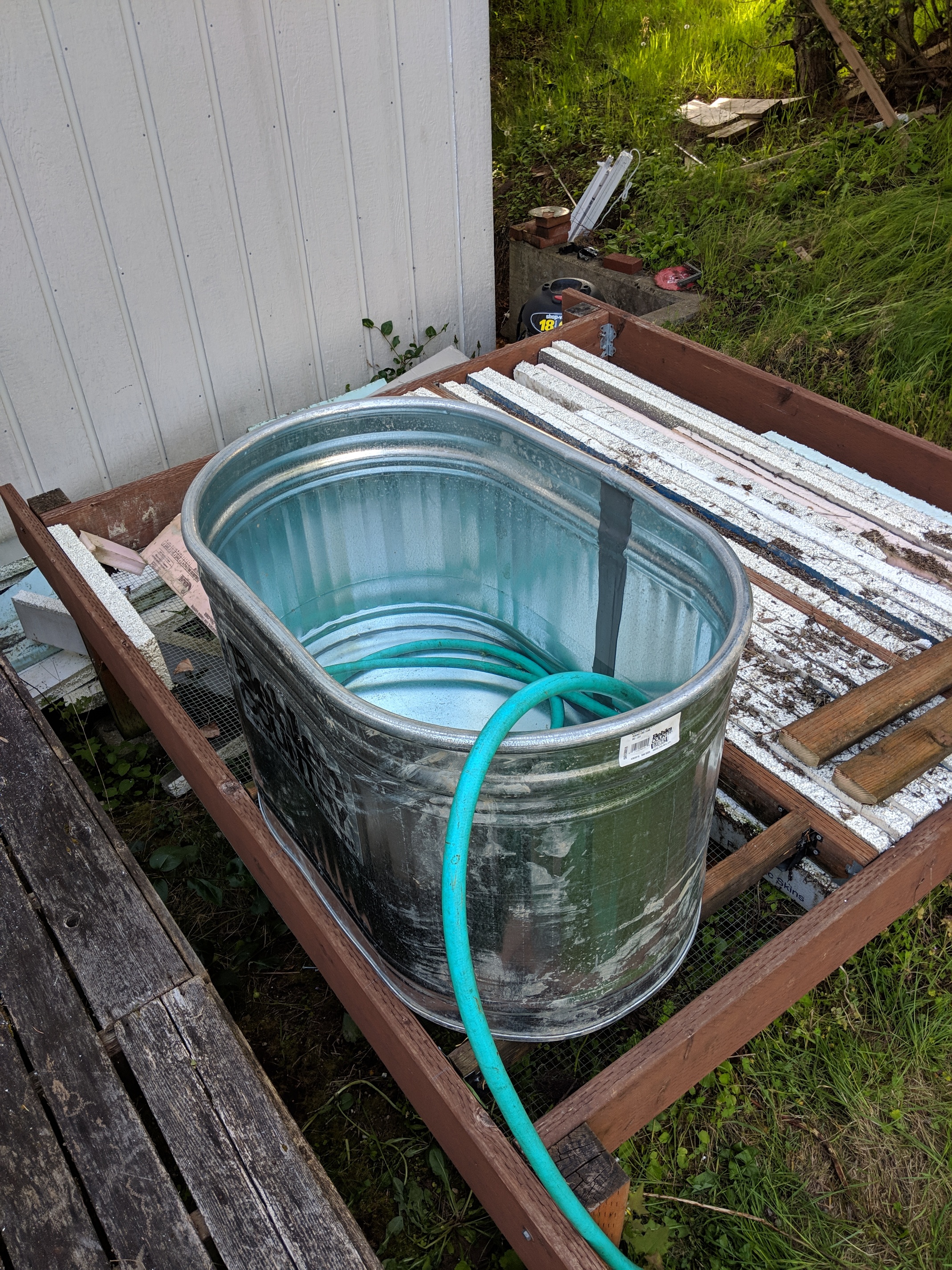
The platform it’s sitting on was originally going to hold a hot tub, but that project did not make it past the “clear cedar is how much?” phase.
Next week I’m going to carve out the holes the wires run through, and actually put the motor assembly in the tub and spin it up. This assumes that the battery box somehow magically assembles itself between now and then.
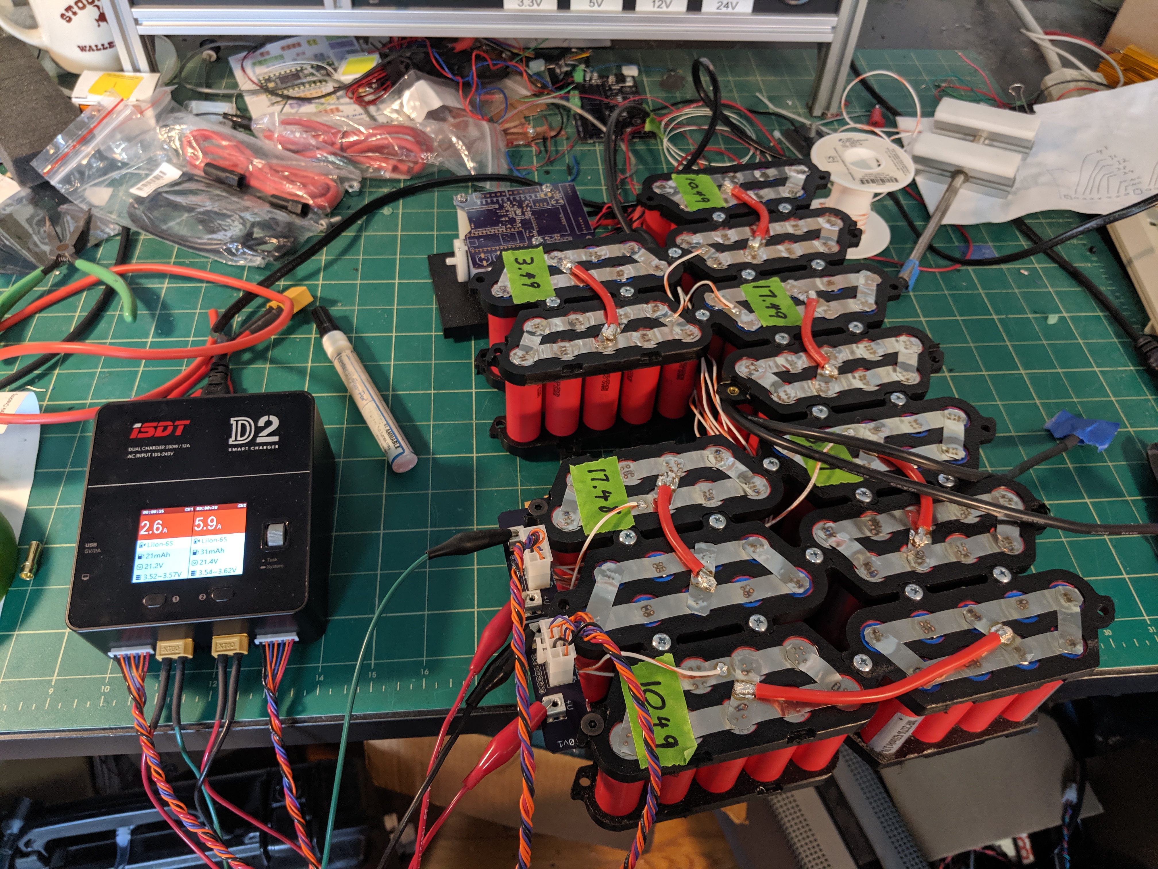
Battery pack is wired and taking its first charge!
I also got all the fittings installed in the battery box
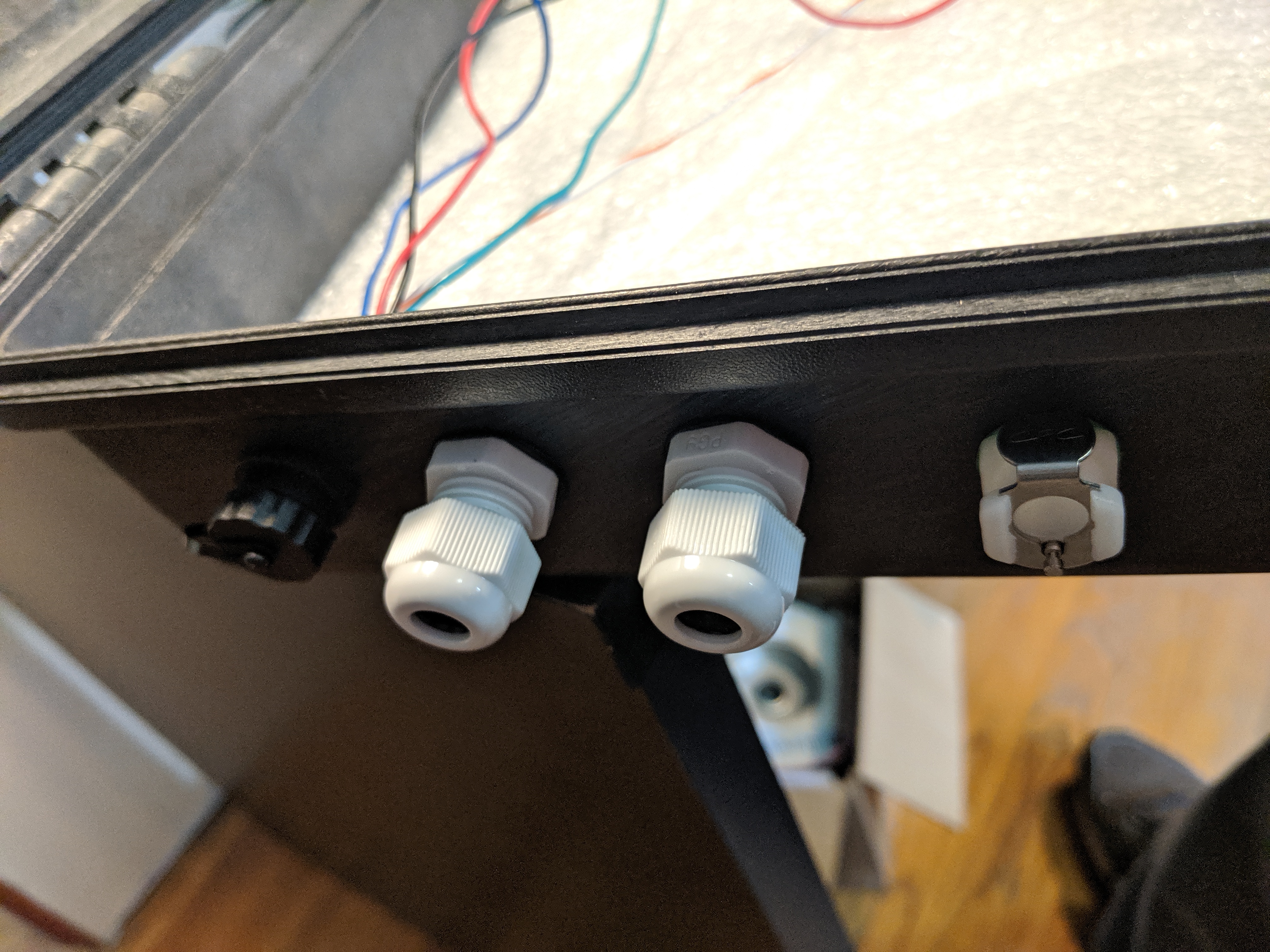
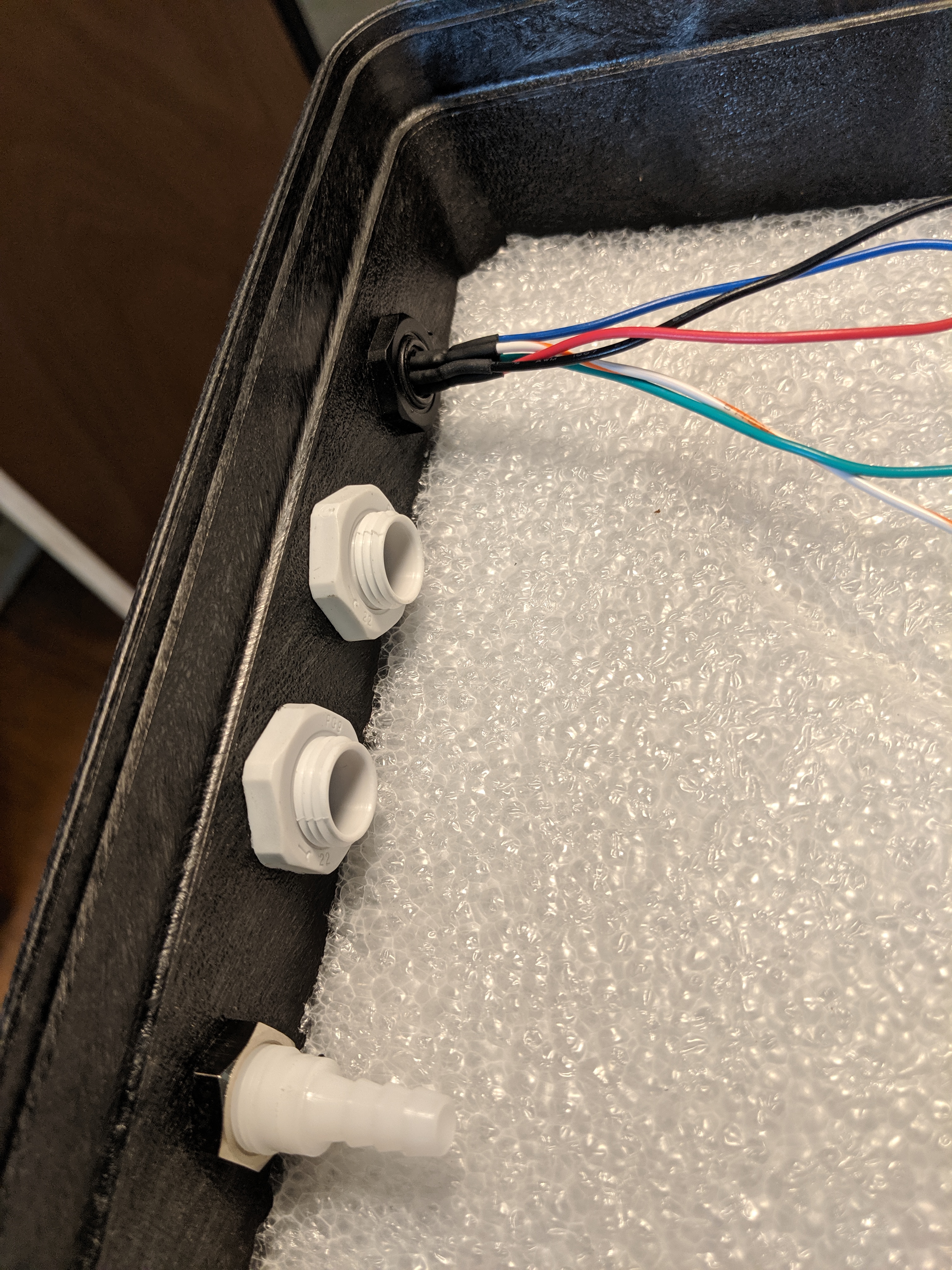
The extra deep cable glands took a while to find, but finally I found them at Digi-Key, which I guess I should have looked at first.
The ones in the pictures are IPG-22294-G (DK 377-2210-ND)
So the battery box should be fully assembled by the end of the weekend. Then it’s time to epoxy the mast mount plate to the board. Hopefully it’ll be sunny enough tomorrow so it will cure properly.
Welcome back. Looks good. Are you balance charging or using a BMS. My battery is behind schedule. I still need to work out some details. Hoping to make some progress this week.
Thanks, it’s good to be back! I got distracted by a toy…

I’m using a balance charger - an ISDT D2, which is a dual 6S charger. I am using the same charge ports that I use on my esk8’s
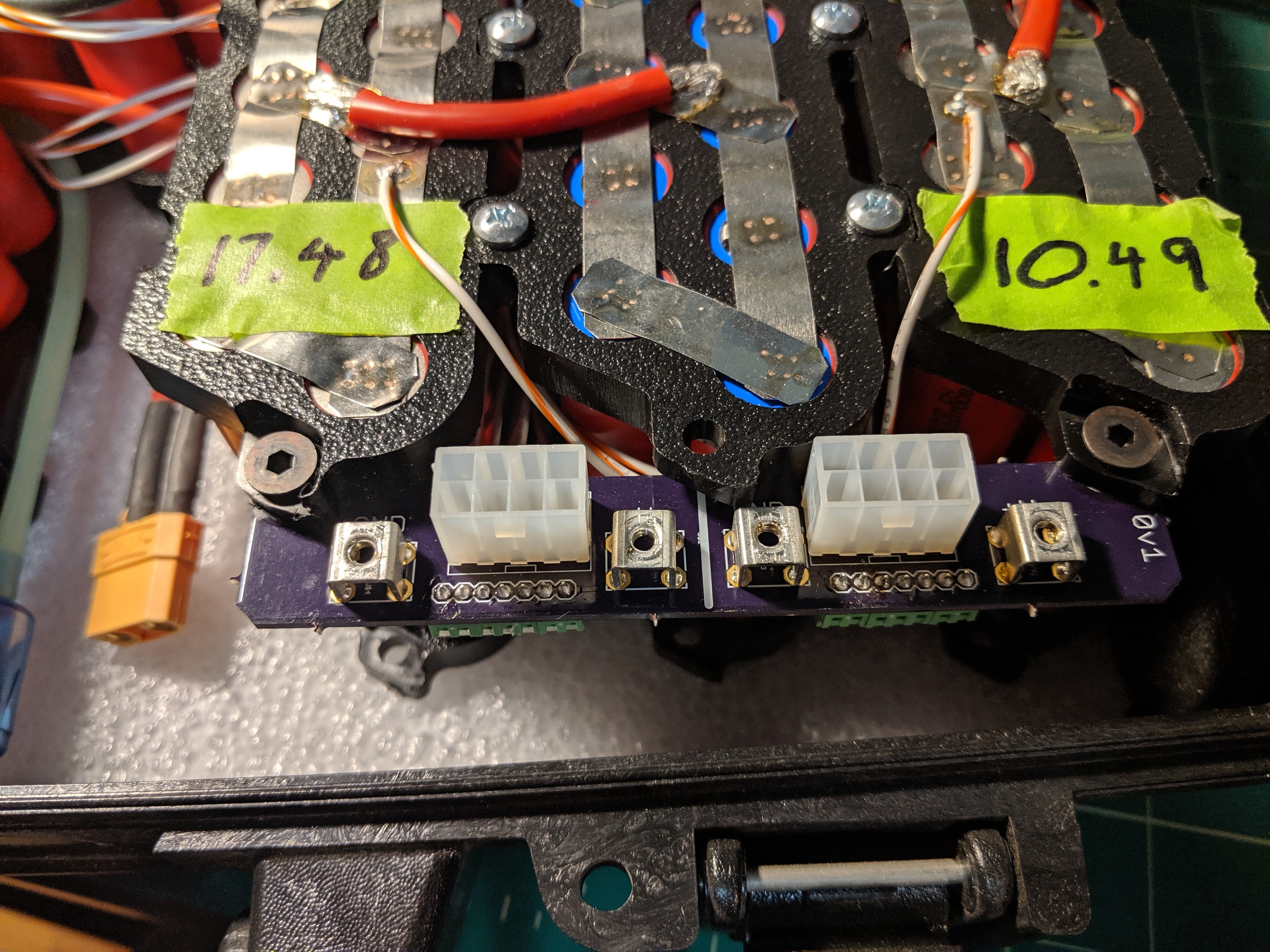
but I had to split it to get it to work with the dual charger. If there is any connection at all between the 2 sides the charger safety’s out, so I have to have a disconnect between the 2 halves (handy place to put a fuse, though right now I just have an XT90, which you can see in the lower left of the picture.
I got the mast mount plate epoxied to the board last weekend and this coming long weekend I’ve managed to allocate a whole day to fiberglassing the 2 insets in the board where the battery box and driver box go.
So in theory I should have a fully complete board in another week ready for tank testing!
2 Likes