Looking at getting some best practices for building packs to minimize fires or bad designs.
I’ll post some pictures of the crappy battery packs I’ve done and what is wrong with them and as well as my new pack as I complete it which hopefully will be way better!
If you have a battery you want people to check out or a design post it here. Expect some criticism
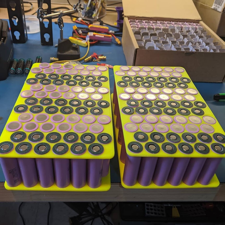
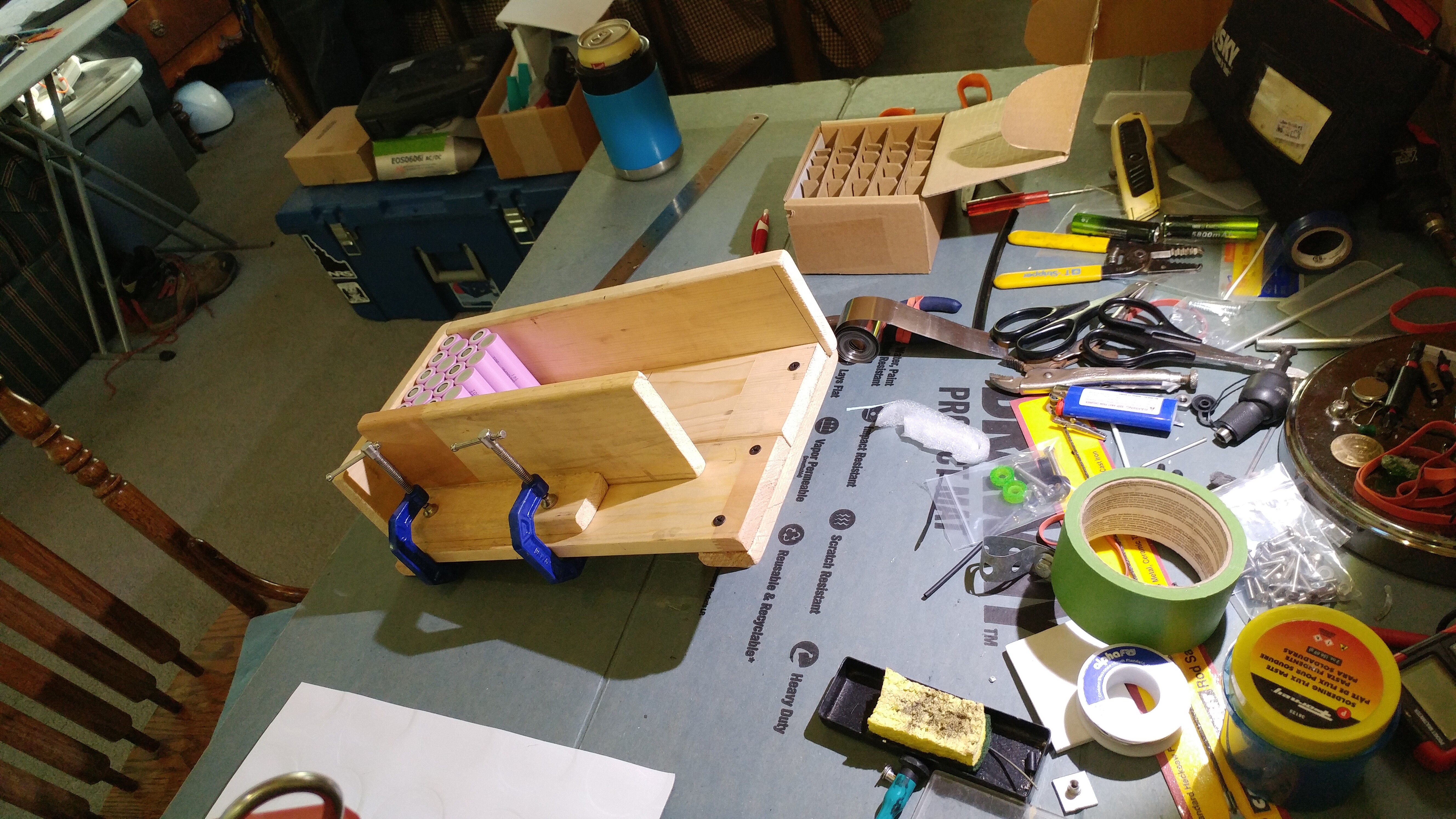
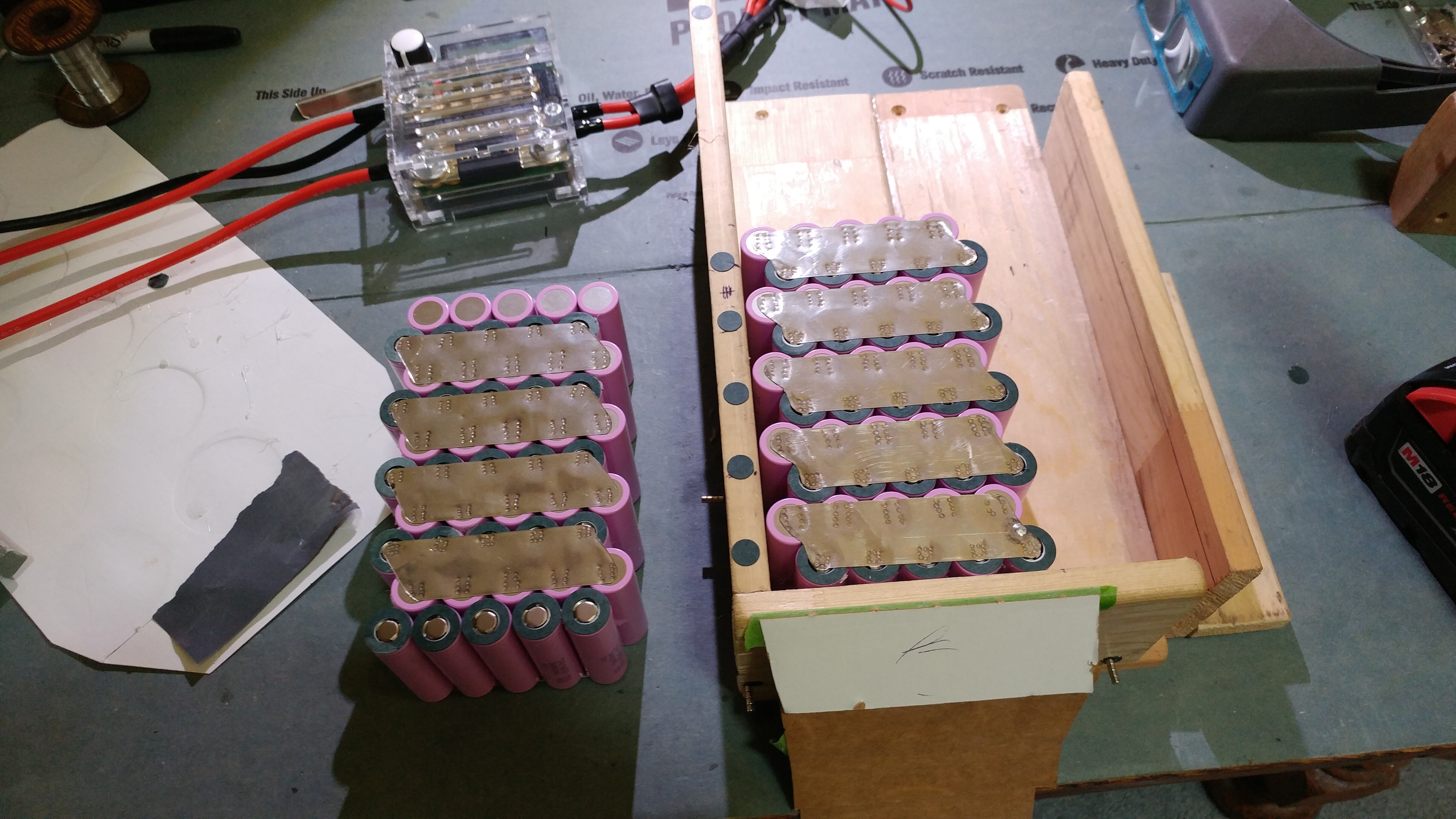
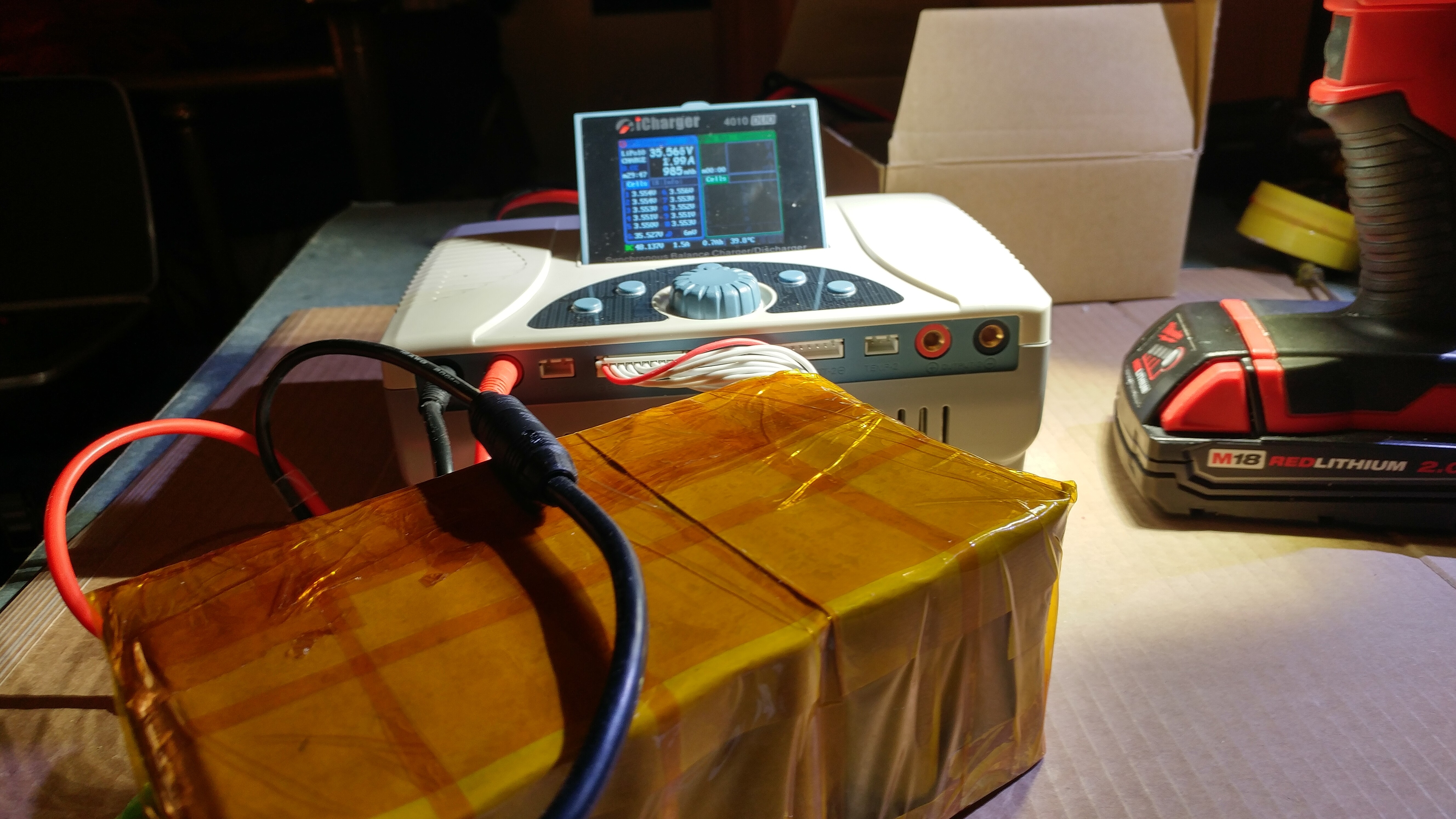
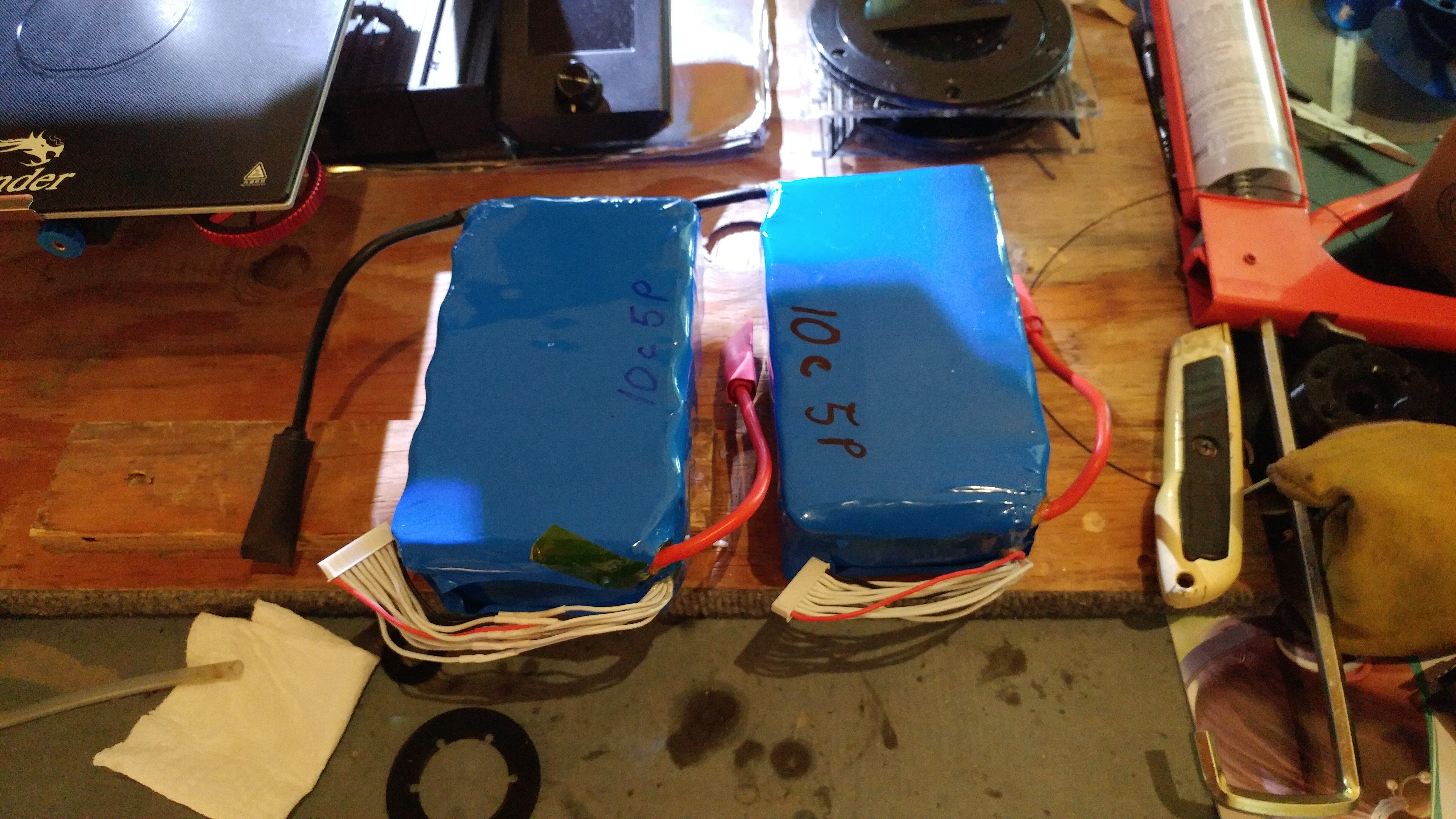
Looks decent so far. 2 6s12p packs so I can use a hobby charger with balance cables to charge it.
The isolation from the 3dprinted holder keeps separate S rows (the set of batteries right next to each but on seperate voltages) other that from shorting out to the next S row. What can happen is the negative can on the battery can short to the negative can on the higher or lower voltage can just next to it if the shrink wrap wears away over time, then you are shorting 2 rows together can get a fire.
Now I wouldn’t set up the P batteries (parallel battery cells) in that configuration. You limit the power by what the nickle strips can carry (I’ll show it in a future picture. The best way is to do the parallel battery cells all in a long row.
Edit: Another thing wrong with it is I used PLA for the battery holder theoretically the batteries could get warm enough where it could cause the PLA to get soft. Like 50C - 60C… although you should never be letting your batteries get that hot…
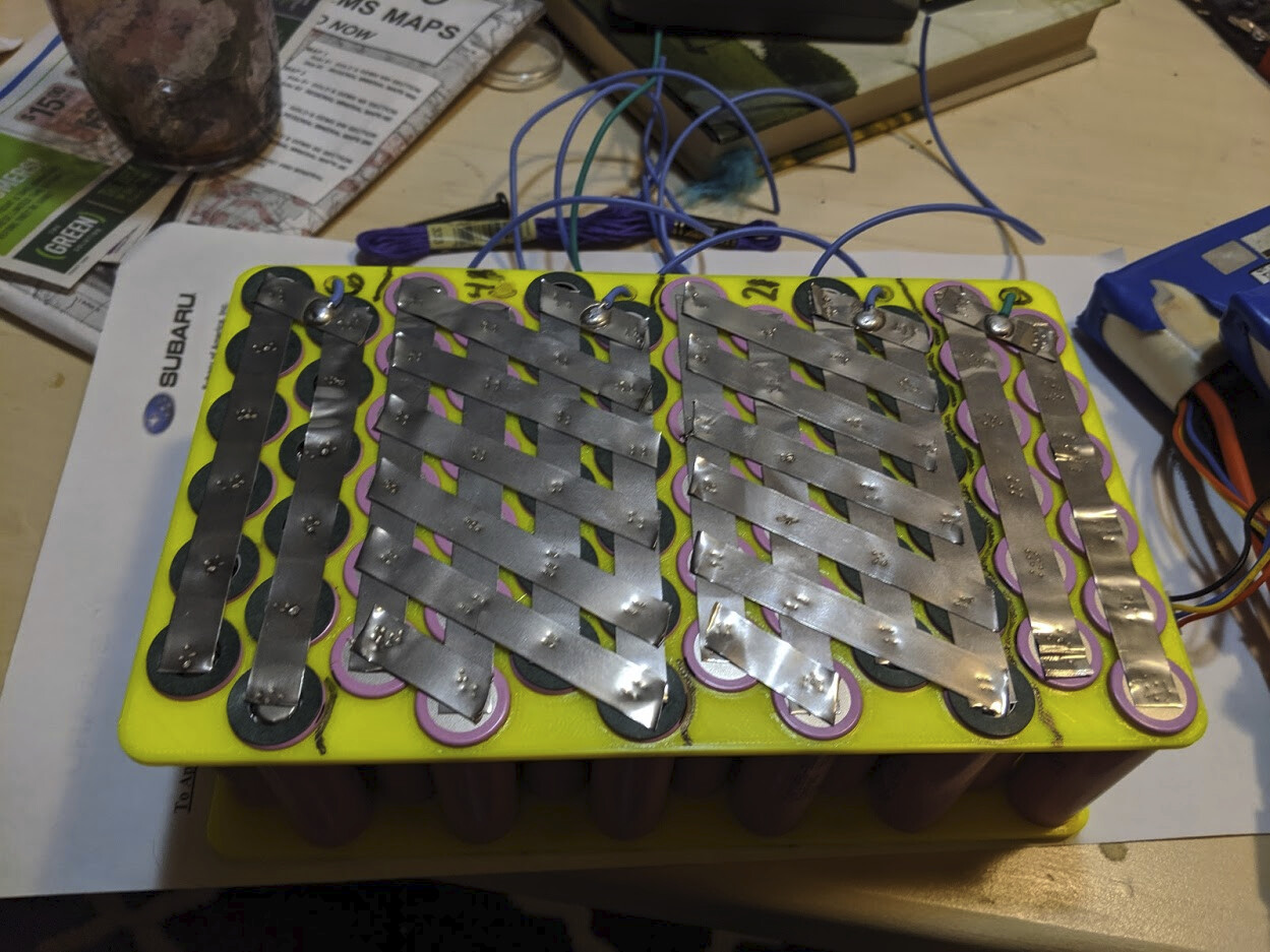
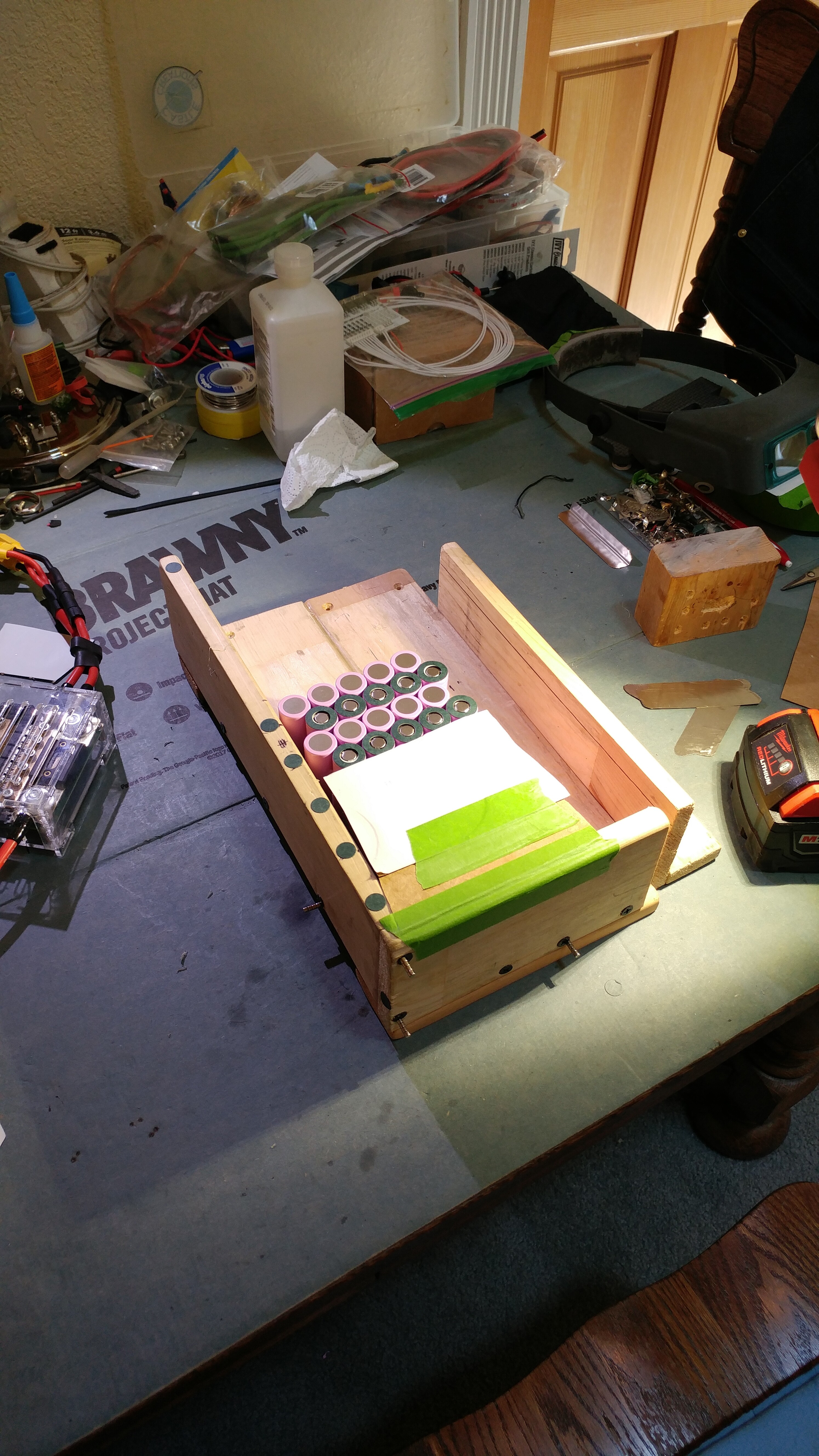
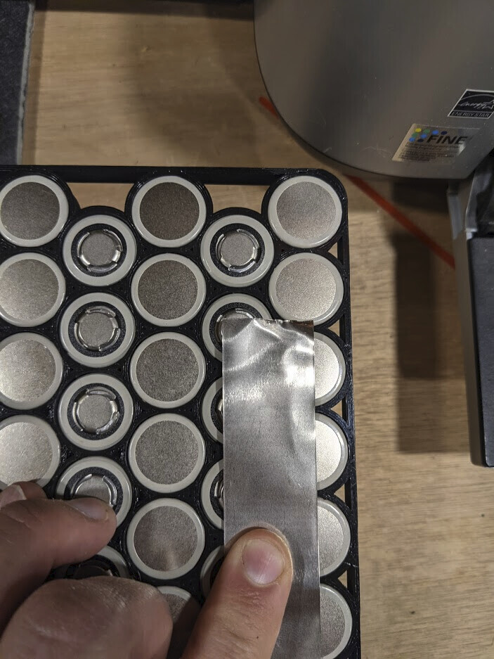
Welds were decent. The fishpaper on the + was good, otherwise the nickel strip could wear down the negitive part of the can (that is just under the green) and short out and start a fire.
Didn’t trim the sharp corners of the nickel strips. Shouldn’t have any sharp points that could cut through balance wire, heatshrink.
Shouldn’t have put the strips connecting + - over the parallel strips, rather some of the newer ladder strips or really wide (30mm) would work way way better.
The current of the battery is limited by the configuration of nickle strips. I have 6 that connect + of the cell to the - of the cell. If I remember right, .2mm nickel strips of the width can do like 10-15A before they start to heat up. So I shouldn’t do more than 60-90A continuous, otherwise the nickels strips will start to dump out a lot of heat, which in turn can damage the pack early. Doing some peak current high is OK (getting up on a foil), but I probably shouldn’t be towing people…
The better way is to do the parallel row all in a line like this:
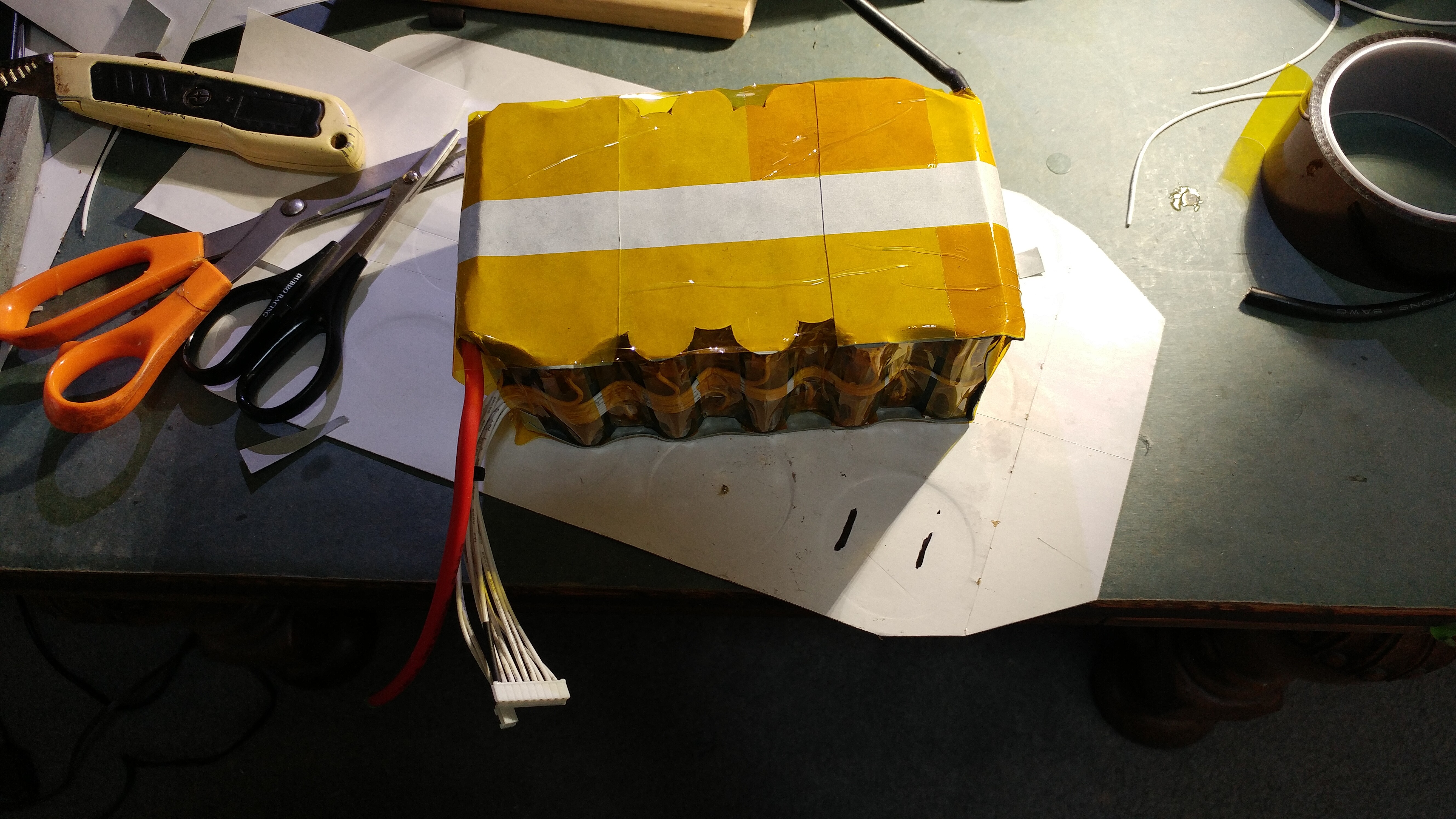
I like those cell spacers, although they can take up more room then diagonally spaced ones, but for many efoil packs that is no problem.
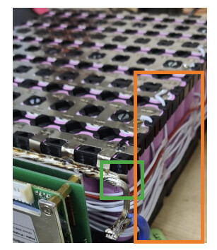
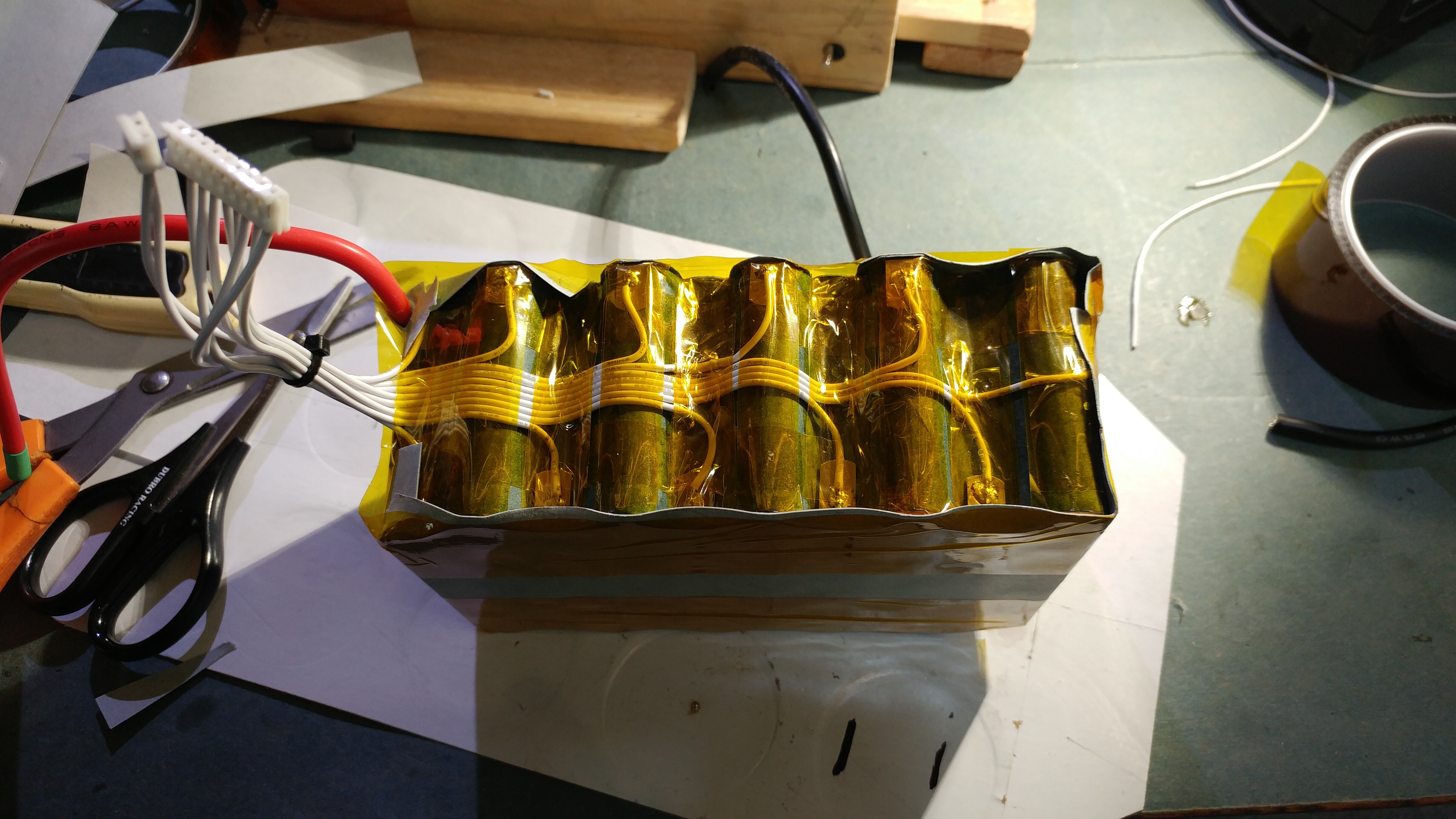
My only criticisms are the green area, I can’t tell if that nickel could reach the cell and get through the heat shrink (with a lot of banging around and bad luck)
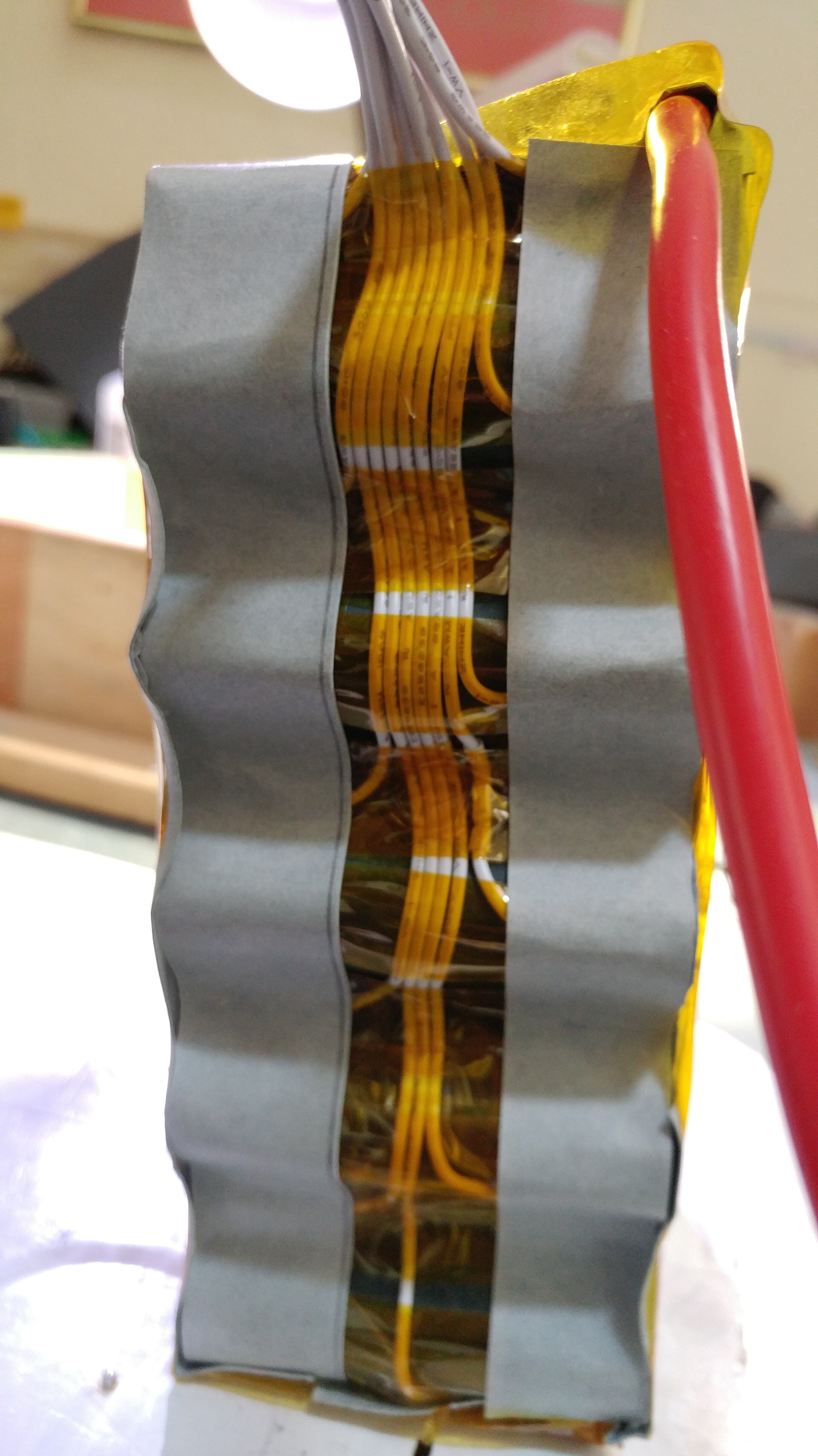
Orange area, I would try to not overlap balance cables and maybe put something behind them if they run over other cells of different S groups (for the same reasons above shorting with lots and lots of bad luck).
This might already be happening, but I might try and run the against the balance cable against the negative part of the cell and glue or tape it to it.
You will see that it depends on the length of the nickel strip , so high amp discharge between cells can be well manage by the strip
But sure you can’t use this for terminal ( bus bar )
So I guess in my case, I had 6 strips of .2mm x 10mm for around 18A * 6strips for 108A total amps in the good temp rating (assuming good bus bar and such as well)
Many test on theses values done ( endless forum) strip with 15mm length doesn’t get hot to all even with +20a
Same as battery made with fuse …
Length and dc courant play a lot
Fuse are very thin , nickel strip fuse add length in circle to get a resistance and blow under amp
I think we need 800-1000A to blow a classic nickel strip
But with the strips added in the battery built , the total resistance may increase the voltage drop
10A across 2 cells is not the at all with 100A on 25cm
Hello brycej,
Need some help diagnosing and fixing an issue I have with a battery pack. Any chance you can help would be greatly appreciated. You can DM me on instagram if thats okay. @CharlotteEfoil
Thanks
Hey @Daniel2020, I’m not an battery expert, but I have been doing some work to build a better one. Post it some pictures on here and maybe someone can help if I don’t know.
I’m building a molicel p42a 21700 pack with 13s6p configuration. These cells should be comfortable putting out 20A each, for 120A combined current output without getting too warm. I’m probably only going to use 30A most of the time on a tow boogie build, but it might be handy for towing. I’m going to stack it in a 13x6 grid with square cell spacers, to allow for short connections between parallel rows.
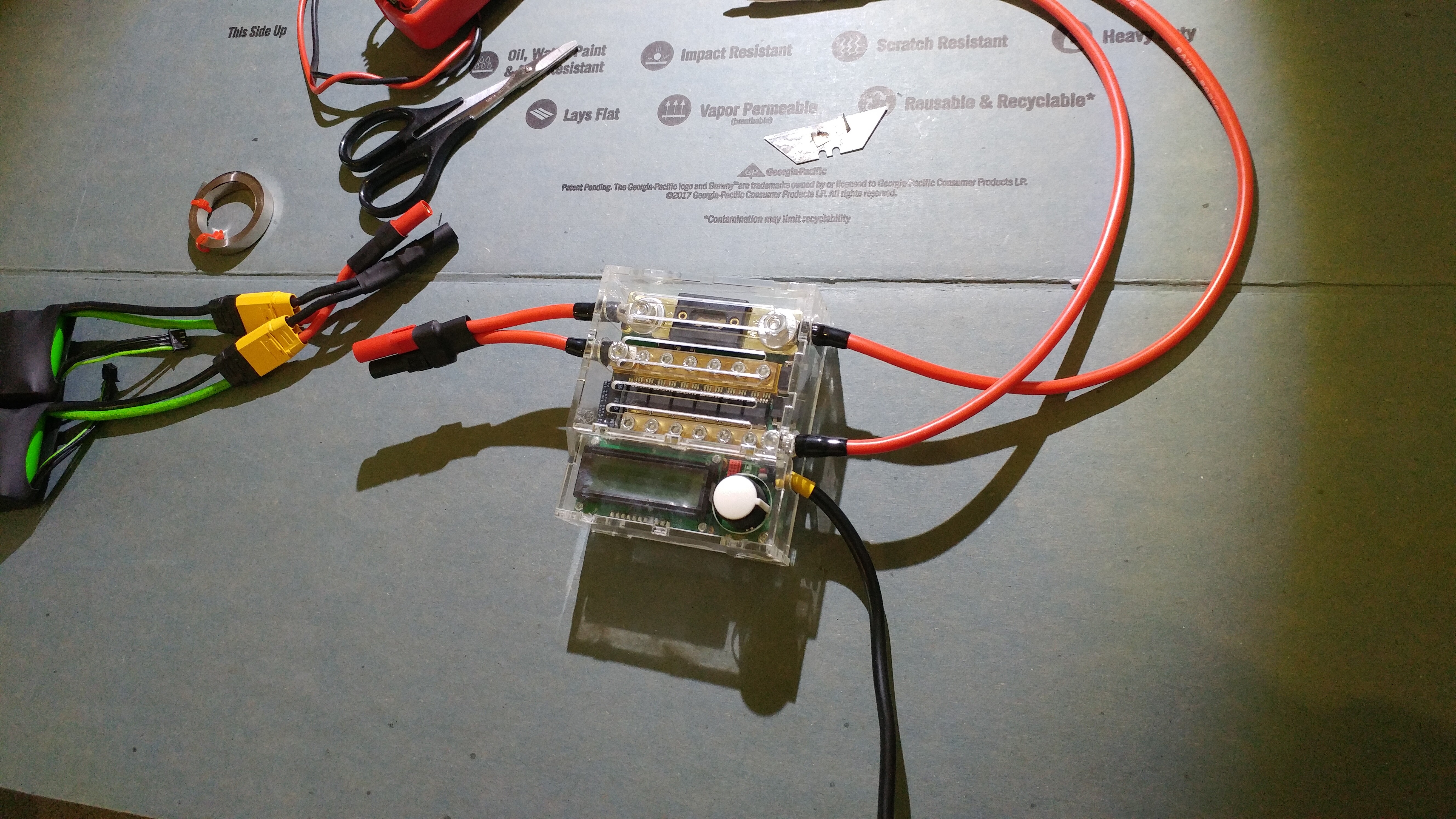
I’ll put a JBD BMS on for charge only, so that it doesn’t limit output. I’ll put fuses on each balance lead where it connects to the cell -ve terminal, and route the BMS cables without crossing them. There will be a big 200A fuse on the output.
I’m debating whether to solder the pack or get a k weld setup. If I solder it, I’ll use a TS100 iron which has pretty good grunt, and I’ll solder a thinner copper solid core wire along the parallel direction, with short pieces of say 16 AWG copper to make series connections for each cell. I won’t bother with individual cell fusing, ala flightjunkie, but his build has inspired me to consider soldering the whole pack - although being more time intensive.
If I decided to go with a spot welder, I’m not keen on using typical strips of nickel, as they won’t be ideal for 20A per cell. I’m interested in spot welding with a sandwich of nickel steel strips 0.1mm over copper 0.1mm sheet, but this will likely require a serious k weld power source. Another option might be to use wide nickel sheet, as the tidy looking kayak31 pics above.
I am stumped about the best power source to use for a k weld, if I did go that way rather than soldering. Not that keen on a lipo that will be stressed and expand due to the heavy load of k weld. A super capacitor setup looks expensive.
It is pretty hard to solder copper with hotspot , you can watch efoil virus Chanel on YouTube , he did that , sandwich copper nickel solder and hotspot all that
I tried this it works but the solder is not strong enough for me
I didn’t push to high the spot weld not to go through the bottom of the cell …
And nickel strip can carry some amp over a short length ( between 2 cells)
I looked up efoil virus on YouTube, and found a vid where he solders and spot welds copper, that looks a bit next level. It seems difficult to spot weld copper.
I think I’d be looking to either solder with copper, or spot weld with nickel plates. I’m leaning towards the solder and copper wire option.
For all my builds in the future, I’m using the wide nickel. That should be able to handle the current no problem and is a way easier build. I have some .2mm x 25mm that I’ll use because I got a bunch of it from fogstar for cheap. Although .2mm x 30mm would look slightly cleaner on the 21700 battery, but I don’t think there will be much loss of current.
For soldering, I wouldn’t recommend it, but other have done it successful with a lot of flux and high wattage iron. Not sure the TS100 will cut it (I have the iron as well and is a great portable one). Any hot spots in the battery may cause higher IR more heating at the higher currents.
The wide nickel looks good, you’re getting 21+mm wide connections from series cell to cell, compared to 8mm strip, so the current capacity will be several times higher. I’d prefer not to waste power from my battery in heat due to resistance of nickel, but it seems the tidiest/easiest option.
Which spot weld setup would you recommend, k weld + what kind of power source?
I could test the ts100 and copper wire on some 18650s I already have, as a trial run.
I am using a kweld with random giant ultracap i had around connected to a dc power supply. I’m not an expert with it yet, used a different welder on my old pack.
Worse case steady state for my efoil is 60-70A on foil, so even with my current crappier battery connections i don’t think I’m generating too much heat, but haven’t really dug into it, since I’m building the new battery. Is be interested in copper if i saw a few more success stories!