I was thinking of the one that comes with the Flipsky kit: Group W7 Water Sports Kit (Includes High Current FSESC75300 /75200 and – FLIPSKY
So maybe 150 amps at start-up. The reason is that it’s the worst commercial prop for e-foils. It is pointed out on the forum all the time, yet more and more builders are buying this prop.
Ok, thanks for the advice. So if I get a better prop it will be around 100 amps. What happens if I do not weld the cells together or maybe just the plus poles. Will the current be unstable or the battery be heating up?
If you need to know this to complete your thesis:-), I would be happy to explain it to you.
You know very well that just spring pressure is used for very simple and simple appliances - TV remote control, desk clock, digital caliper, PC mouse etc etc.
But the e-foil is one of the most demanding devices in the world with regard to very high motor power.
It therefore makes no sense to dwell on the issue of the worst possible way to connect the positive and negative poles of batteries. Another mistake is that your solution does not seem to consider charge protection in the form of a BMS.
Here on the forum there are many examples of very simple, very reliable and very efficient connection of positive and negative battery poles.
Hi @MartinS,
There are people in the esk8 community that use these types of packs. They are call compression packs and they can do very high currents, although I haven’t see any on the efoil side of things.
Personally I’d for air travel, I’d make 4 square packs and put them in a waterproof box on the efoil. Although i thought air travel could only do 100wh max per pack. For my 12s12p it is 36Ah at ~45V for 1620WH. That would seem to require 16 separate packs, and it looks like total is only 300WH, so not sure how that would work.
Also yes that prop stinks. If you are in europe here is a good cheap option: https://www.custommotorsfrance.com/product/propeller-complete/
@Dynamik Have you built an efoil board or made a battery yet?
Thanks for this lead @brycej. I’ve been searching for an air transport solution for the 18650s and wasn’t aware of the compression cell holder approaches. These are helpful.
Next, adapt a way to contain and make them water tight for efoils.
Prior to your post, I saw this post on the forum, which I was considering how to adapt for efoils:
Has anyone here had success building portable efoil batteries for air transport?
If I was going to do it,
Max our series pack with 100WH and you can have 2 spare batteries.
A P42A is about 15WH. So that is 6 batteries in a P row (20-30 minute foil time). Then need 12 or 14 or 16 separate packs for series row.
So You’ll need a family of 4-5 to carry on all your extra batteries, Then connect all the series rows when you arrive.
Seems like a PITA though, I probably would just pay to ship the battery down and built a really robust battery.
1 Like
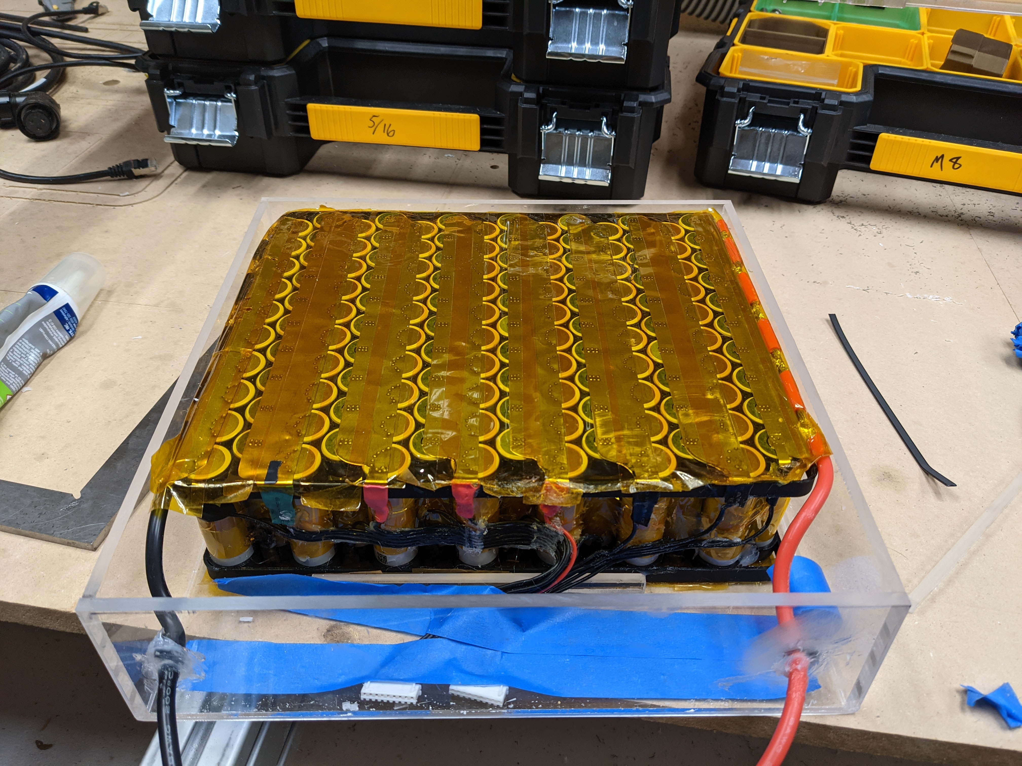
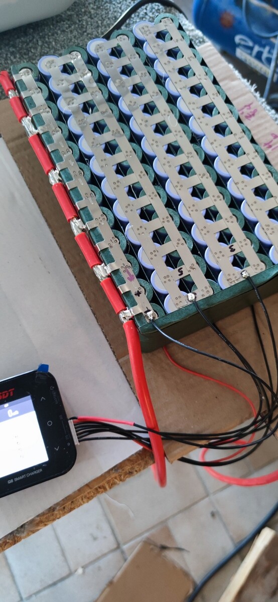
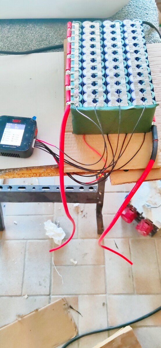
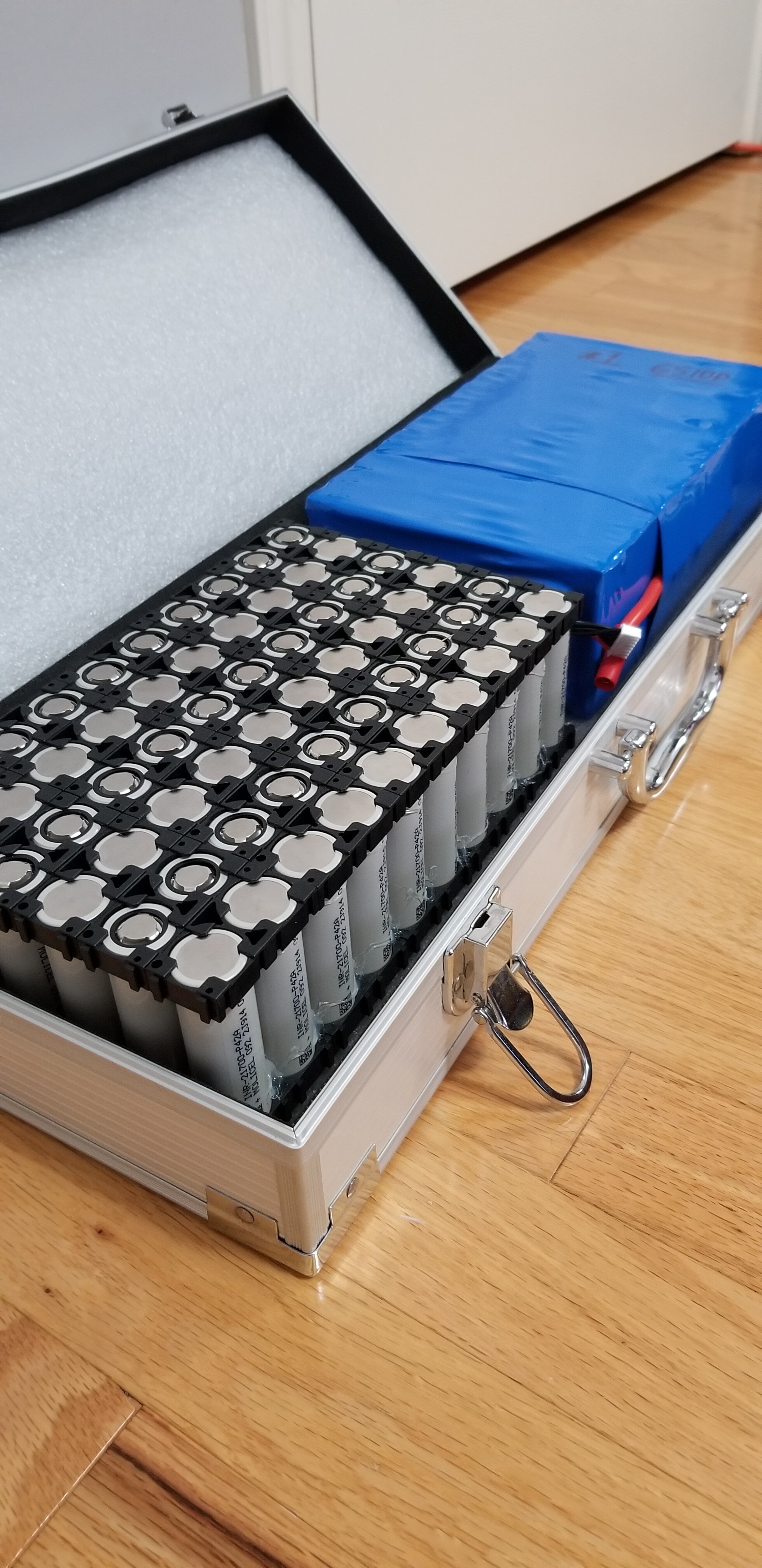
Got the case built for the battery. Hooked up my custom BMS while charging for balancing but it didn’t need to do much at all.
None my glands could fit though the 1/2 inch acrylic so I drilled holes, sanded sharp edges, put a ziptie on the wire inside for strain relief and siliconed the wires in.
Might try and find a better solution in the future.
Added the top with vhb tape and a 1/4 inch piece.
Going to try it out this weekend!
2 Likes
Good work brycej, looks tidy. Could you countersink the holes to fit the cable glands?
I used 4.5mm polycarbonate, which allowed a couple of threads of engagement on the lockings with PG9 glands (w rubber seal removed). Polycarbonate is much stronger than acrylic, and easier to drill without cracking. Adding some extra strips of polycarbonate in the corners allows plenty of glue area and stiffness. They make a very fine angled polycarbonate trim strip which I used along the long edges, and to provide a wider seal area for the lid.
2 Likes
Couldn’t you use the cable gland in a drilled and tapped hole without the nut? I often do this in thicker aluminium. depending on the gland size it might be a pretty common tap (M12 or M14)
1 Like
Great idea @npak! I do have a tap set and I think I have that size.
@Jatem if i had my CNC up and running I probably would have done that.
I was pressed for time to get it done. Currently camping in SD and had a great kite foil session on the Missouri river this evening! If there is wind I still would rather kitefoil then efoil. Might try for a dawn patrol session tomorrow before we continue on the road. I want to compare the new 14s vs the old 12s!
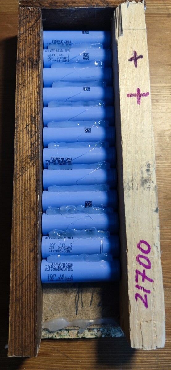
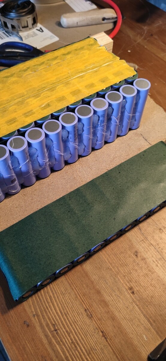
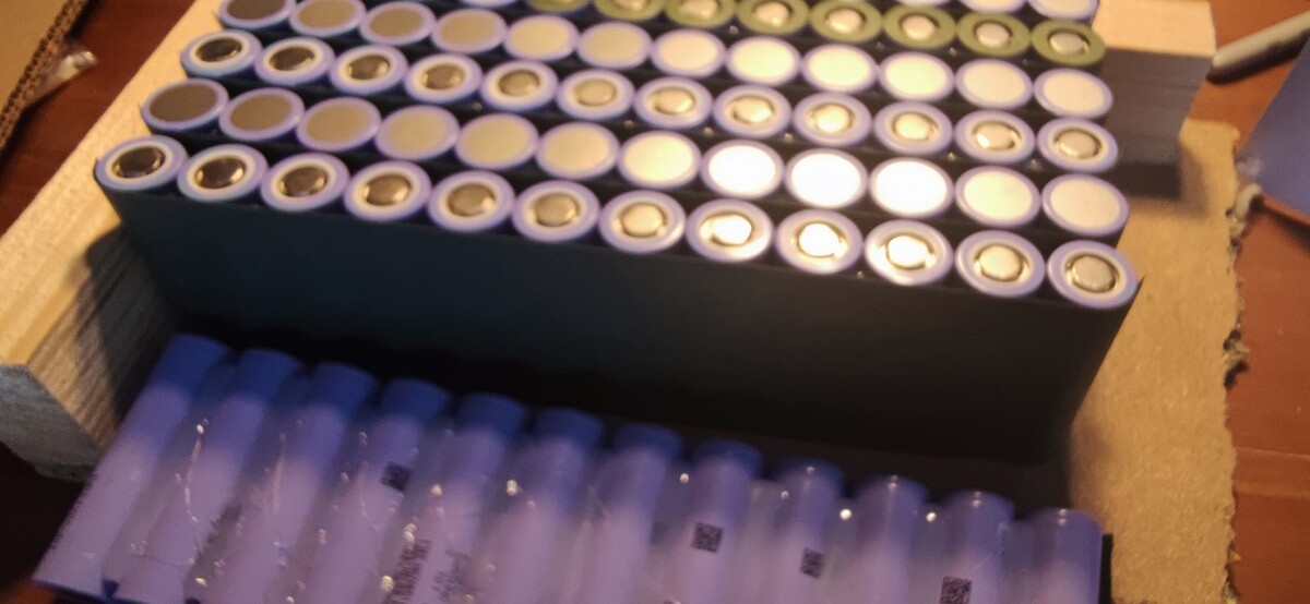
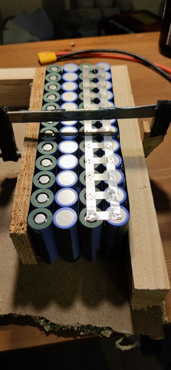
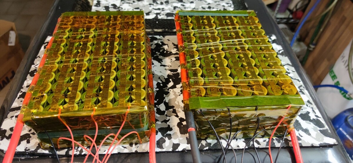
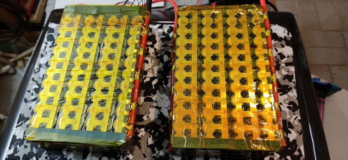
Two soldered 6S10P 21700 batteries. 0.45 mm copper sheet used for bars. 80W soldering iron is enough for this job. Many thanks to funboards.at
7 Likes
I’m looking forward in building a 12s12p battery with 18650 cells. What size of nickel strips should I buy? Will 0.2mm x 8mm heat due to resistance?
Thanks for sharing! Soldering the batteries especially with that amount of surface area is really hard on them. I would expect to lose some life/capacity. There is a reason why any professional pack won’t have any soldered cells in it.
There are a few people around here that solder fuse wires for protection, but I wouldn’t even do that personally.
My quick search didn’t turn up too much actual data, so maybe it isn’t as bad at I think…
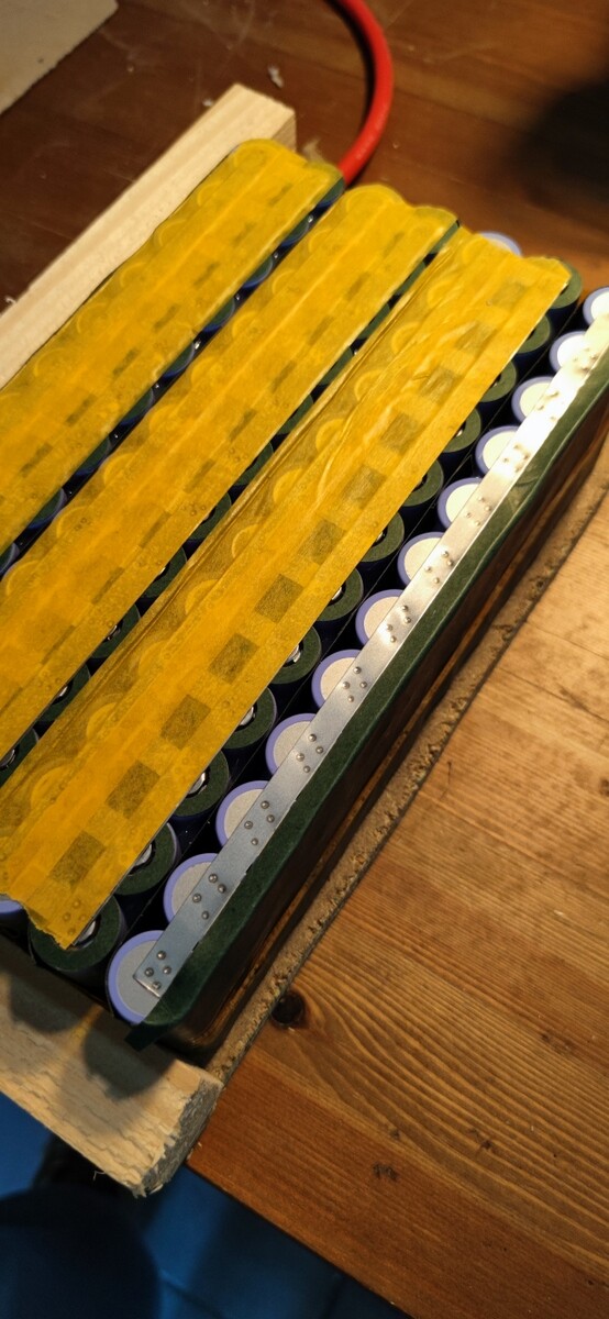
0.2 mm x 25mm or maybe 0.2 mm x 20mm. Can’t remember the ideal size for 18650. The wider strips is way way easier to work with, less error prone, better current!
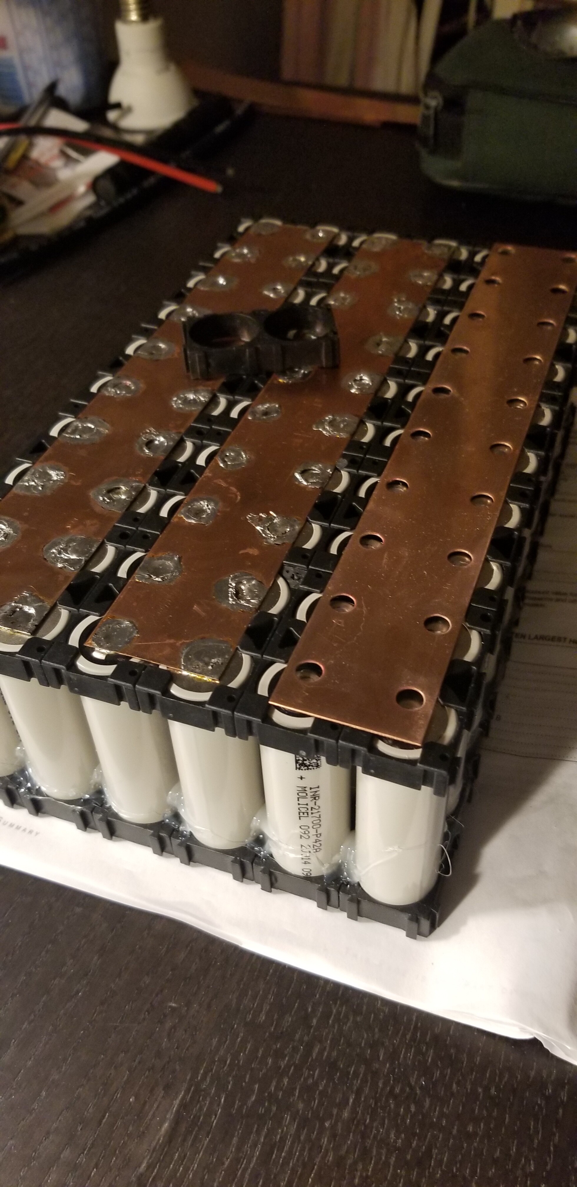
I used 0.2 mm x 25mm on my diagonally connected 21700 and it fit but 30mm would have been slightly better.

2 Likes
It’s much better to use a wider strip so you don’t need to stack strips. Using smaller strips for serial connection will be a bottleneck so use wider strips as Brycej is doing.
Do minimum four welds on each end with 18650 Don’t weld/solder in the center of the the negative side.
2 Likes
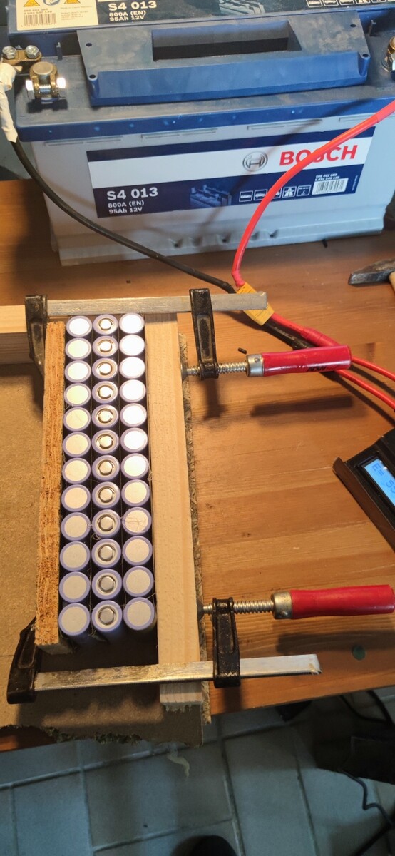
Hi! How can i get all my cells on the same voltage so I can solder them together? And what voltage difference is okay?
(I’m going to build a 12s12p battery with 18650 samsung q30)
1 Like
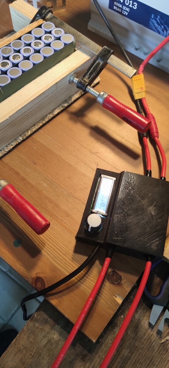
what voltage difference is ok ? i would say 0.1-0.2v never find a answer on that, so i grad 3.2v cell and a 4.1v cell (30Q) put them in // and measured 0.7A of current between them (delta 0.9v)
but i didn’t weld 12 cells together like that, and if it’s done i didn’t think you can know the current flow during the time your row balance itself, eventually measured heat?
i will stick to 0.1-0.2v just not to worry even if i think we can go higher (on good cells with low IR)
and this is not a problem at all, what is pretty scary is taking a battery a part and pull the spot weld on + ;), so do it really nice the first time and think about all the wiring, solding, bus bar, balance wires before spot welding
1 Like