Looking good! I have a similar setup and I’m using the 150A fuse, which holds up good with the vesc limited at 130A.
2 Likes
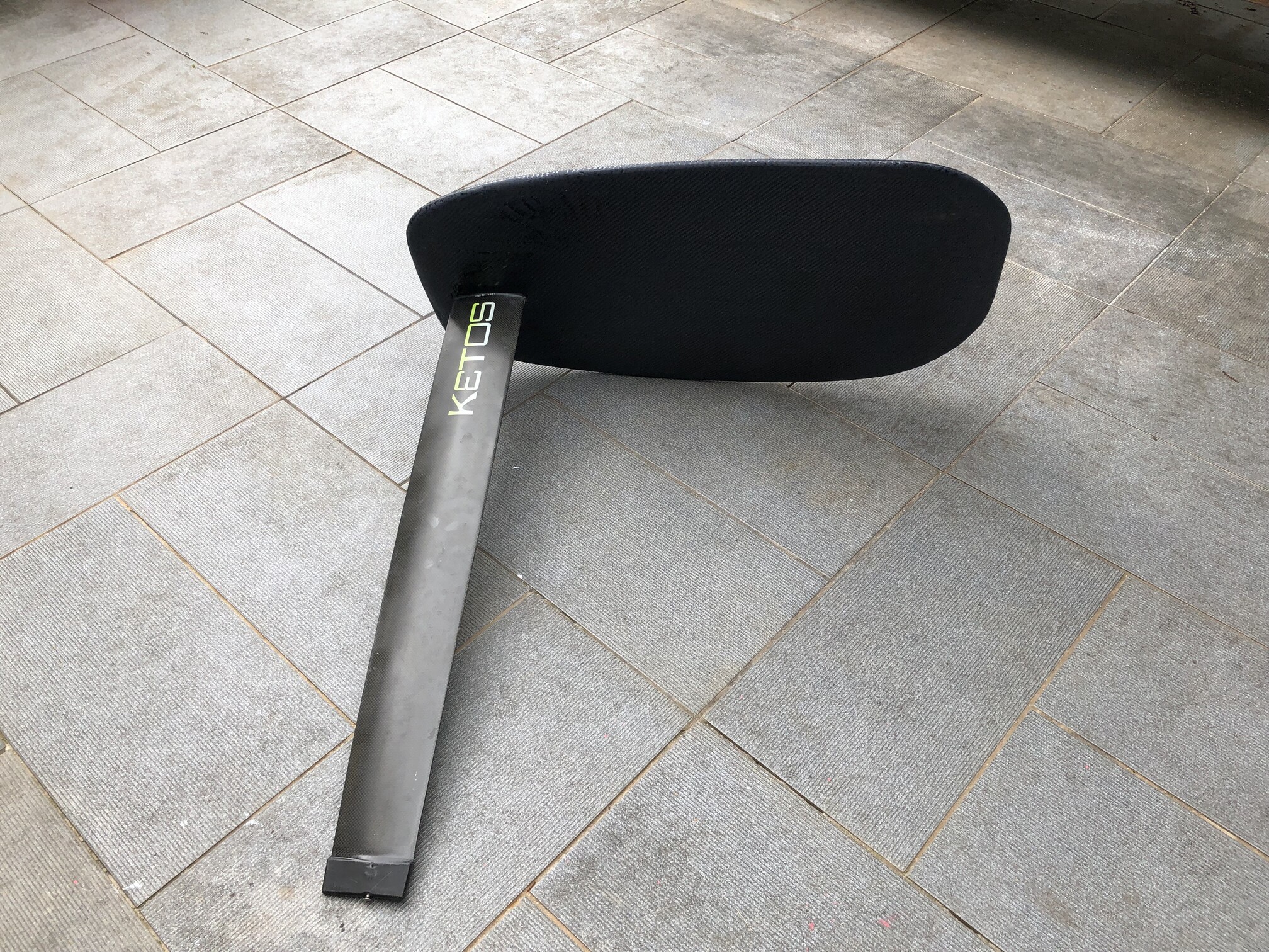
I haven’t posted for a while. I shaped some foil pocket boards ![]()
My last session with my V4, today
Ebron ( lake Monteynard)

5 Likes
Congrats, looks very professional.
Q1: How is the process different compared to the V4 efoil board ? Foam core, fabrics layers ?
Q2: Will you make your efoil boards this way from now with tinted resins ?
Q3; Any picts of the different steps ?
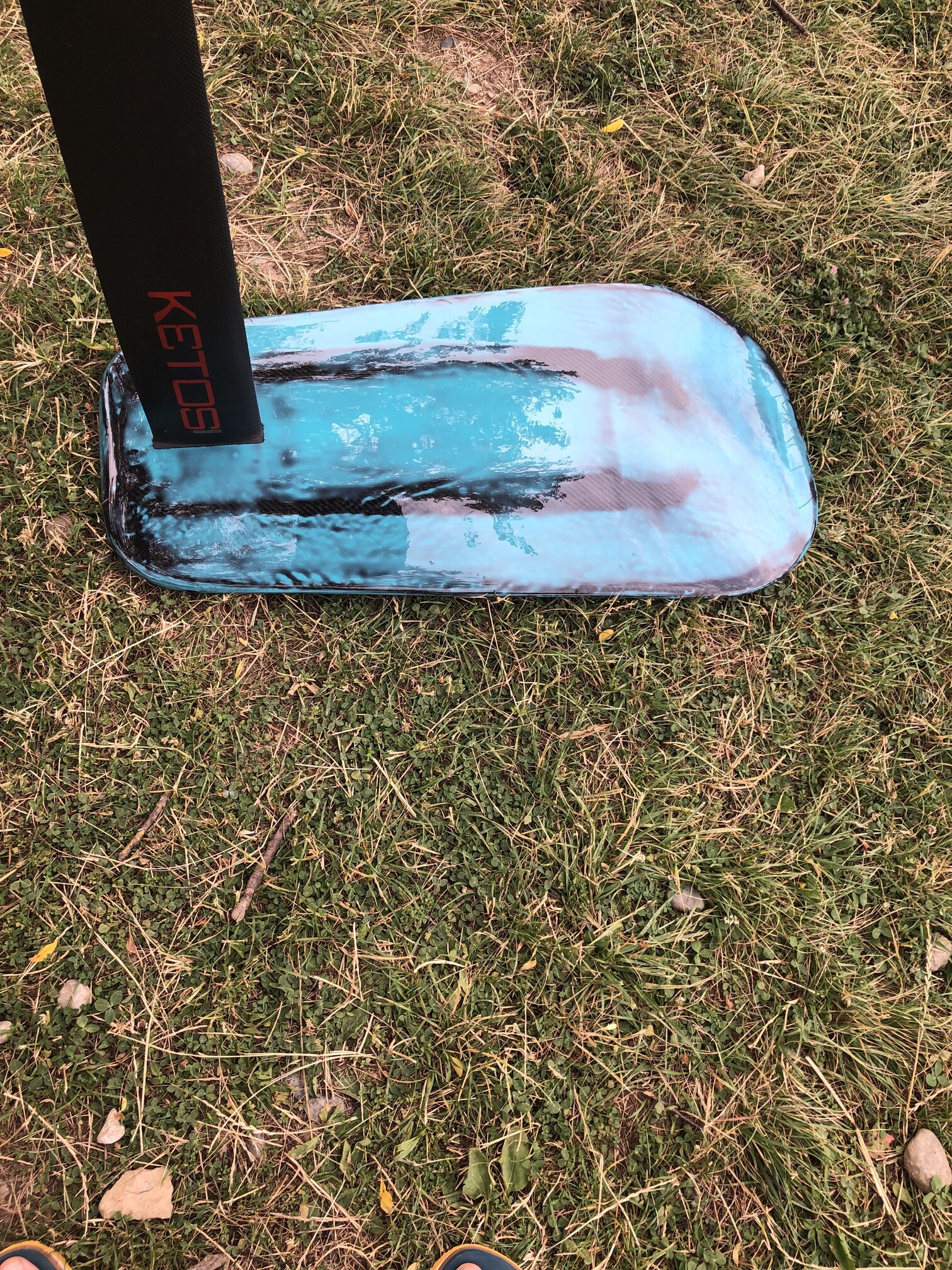
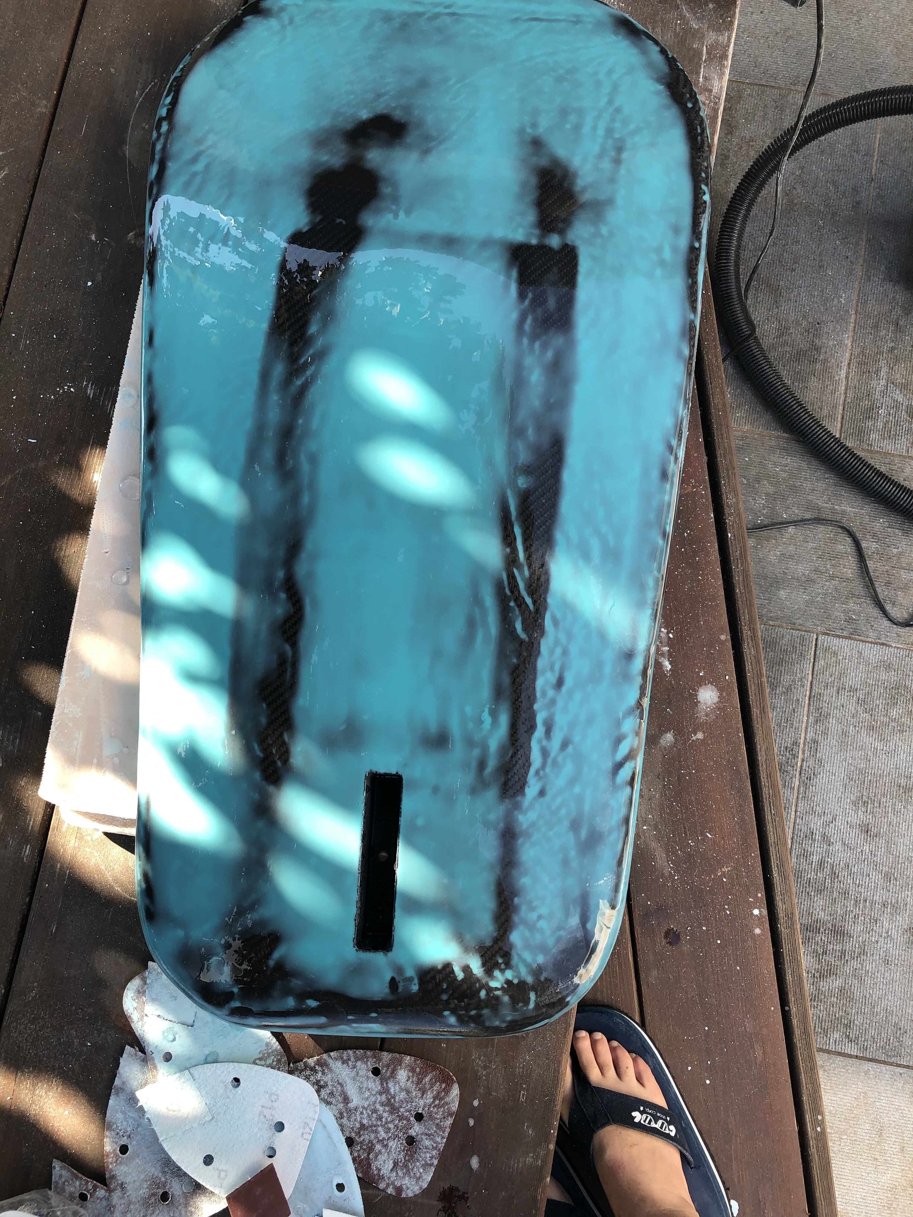
Same construction like my V4, 3 cabon layer below and 2 above.
and I finished with sanded colored resin. and a epoxy coating.
core “styrodur”, KFBox in with 2 airex 20mm
Construction under vacuum. board weight : without pad 1.2kg 
height : 85cm


1 Like
Q2: Will you make your efoil boards this way from now with tinted resins ?
Yes, because it’s more easy for a perfect finishes
Q3; Any picts of the different steps
no sorry
Hi @jeffM , Congratulations on your work, I think many of us follow your progress.
I have 3 questions:
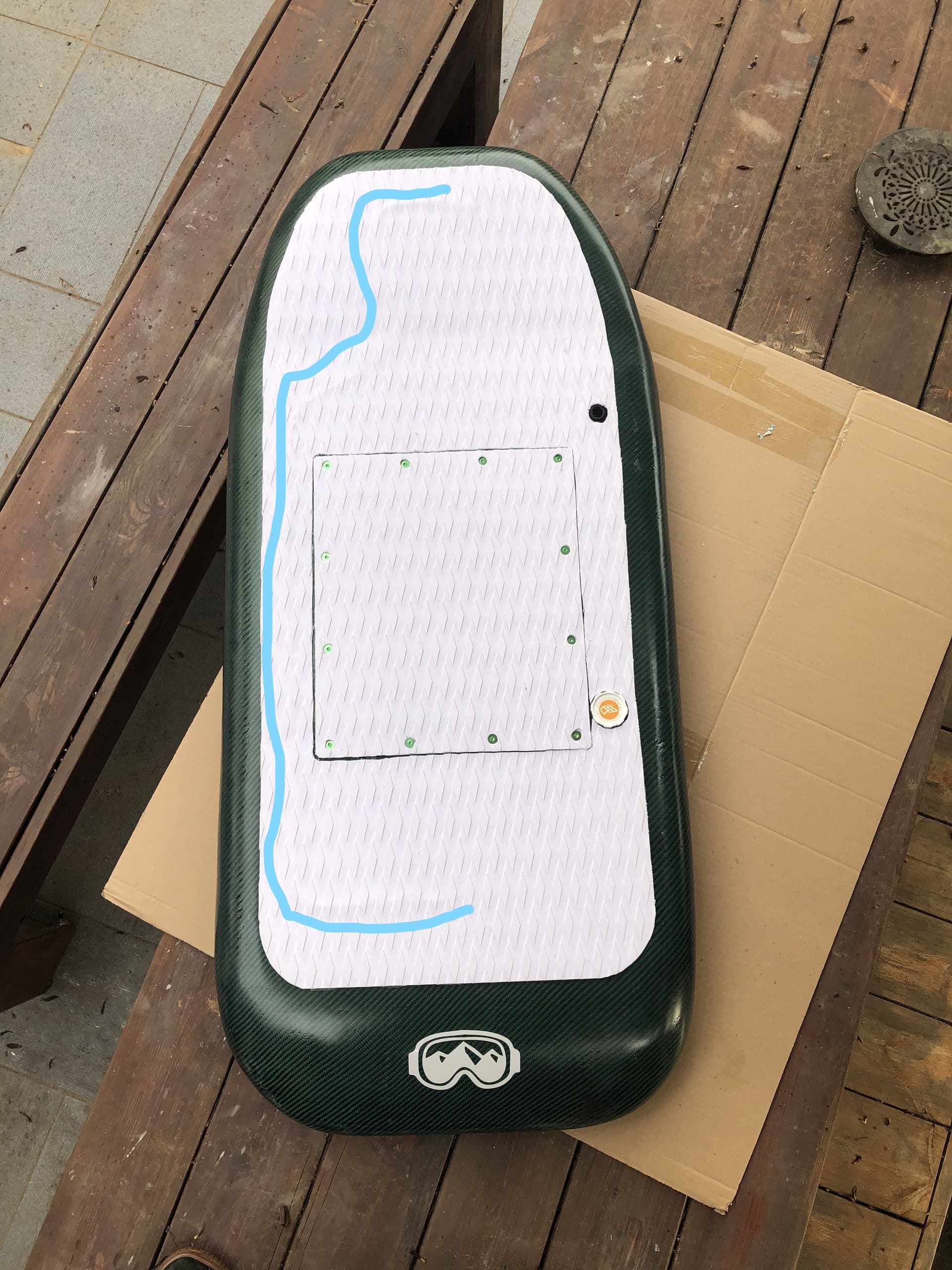
1.- The antenna that you take out of the mast together with the battery connectors is the FLIPSKY VX3 antenna, you place it under the carbon fiber throughout the deck, right?
2.- What is the TRAMPA nrf wireless dongle for? I get the impression that you program the VESC via USB. Is it to be able to configure after potting?
3.- Is the wiring between TRAP dongle / Usplit / FLIPSKY VX3 simple / intuitive?
If you answer, thank you very much, and if you do not see the message, thank you very much for all your work, it is very graphic and it is a great help.
Greetings
2 Likes
Hi
1-My first antenna was under the carbon, but it was too short
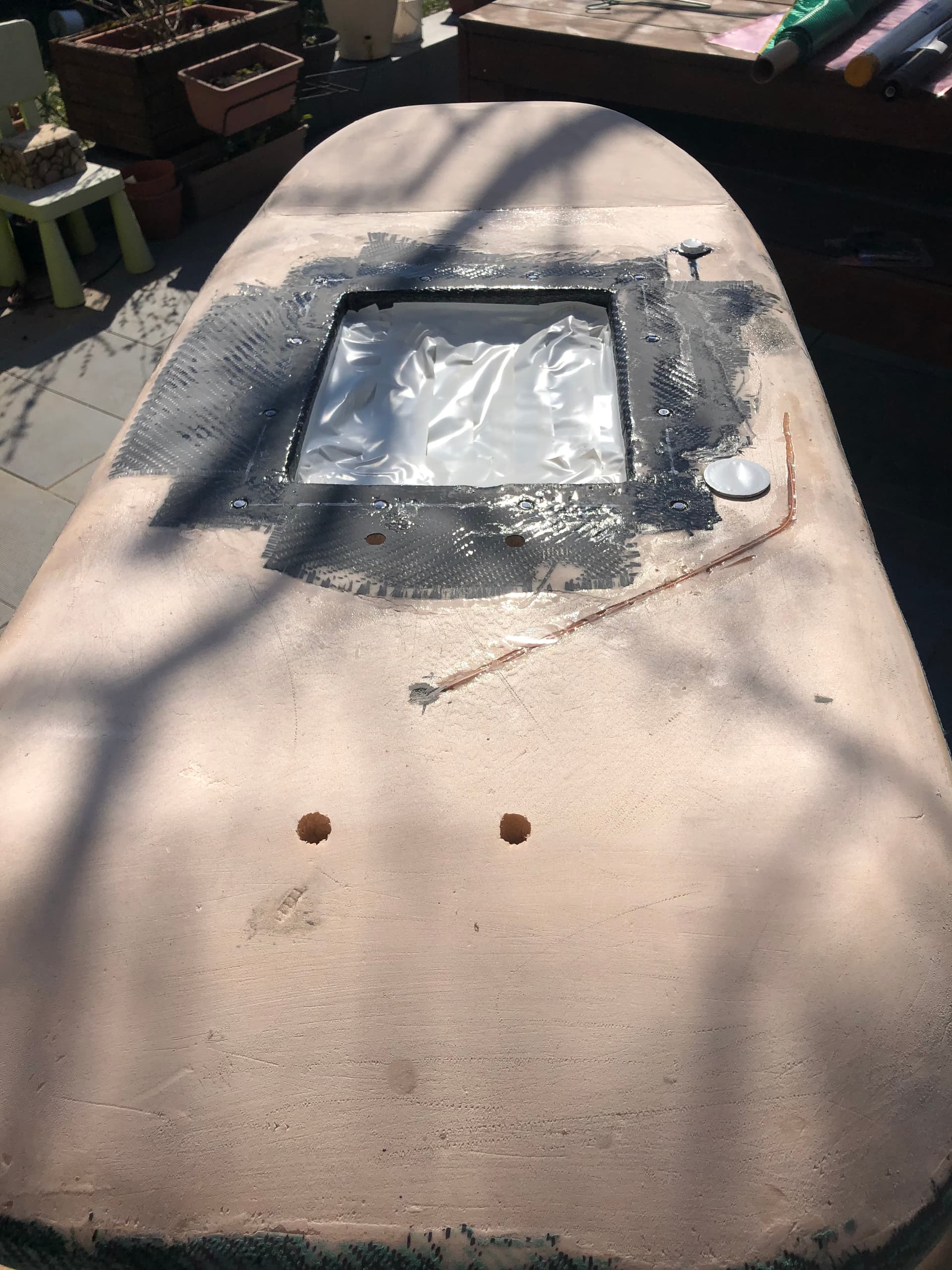
so I added an other antenna under the pad
2- for program the VESC with my phone
3- yes it’s easy you have all the schematics with the usplit, but you need to redo some cables
1 Like
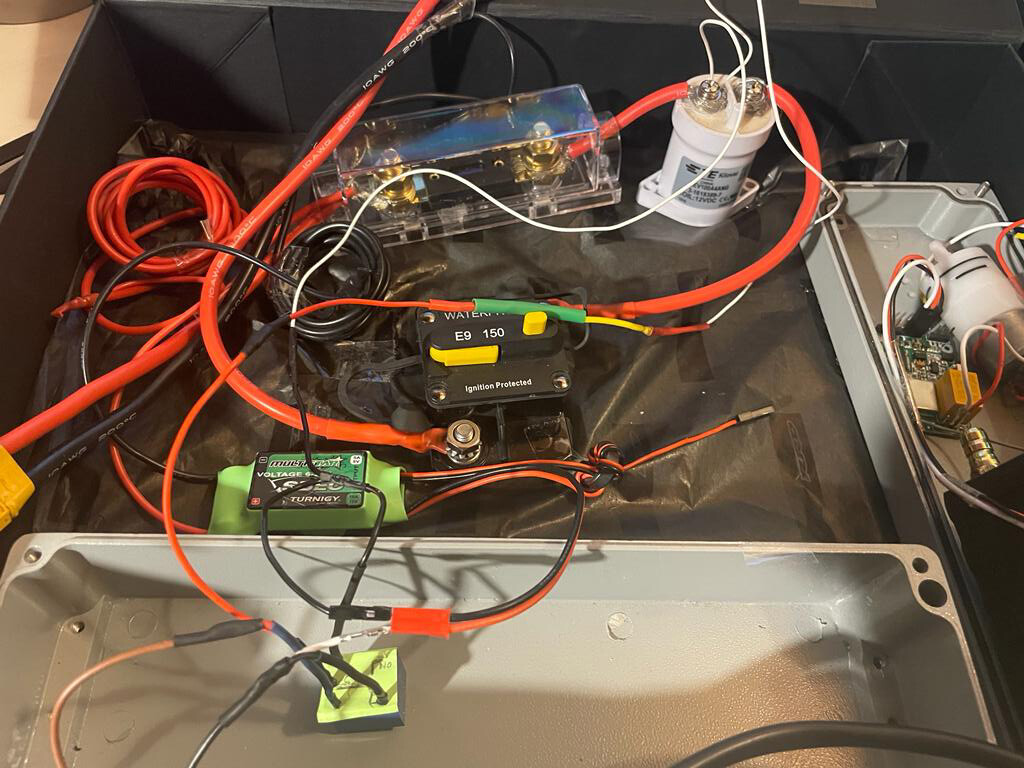
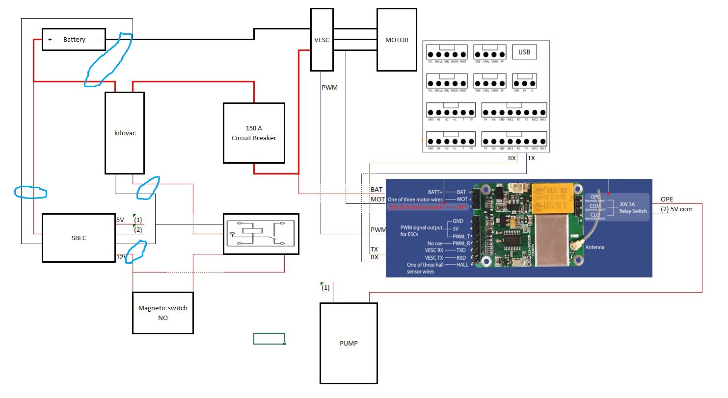
I ask you for a hand i’m following jeff’s first wiring diagram i managed to make it work, but now it doesn’t work anymore. I’m lost! where I am wrong I hope it is a stupid mistake and that I have not done damage to the bms, where I am focusing the suspicions on the malfunction. When I start the bms it locks up when I turn it off you hear the kilovac release. I disconnected everything else in preventive mode. If you are patient, I also made a video.
https://youtu.be/y-ciJlE9zk0
Thanks I hope for some help
Well done amazing job !!! I going trough my project at the moment and I got couple of idea from your build !! Thanks
Why do connect red cable all the way from the last row of cells ?
Do you do the same of the black side ?
I m building a 12S10pm by divided in 2 so no bms for charging/discharging and I used my RC charger for 6S
Here some comments . By the way, your video is private, at least was not able to open.
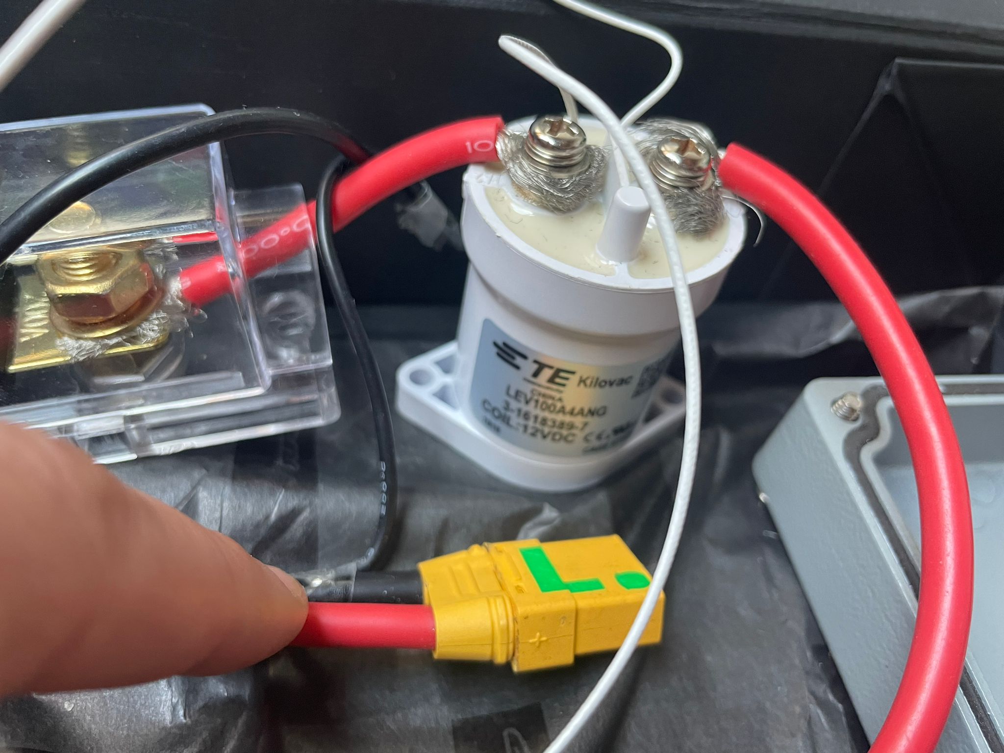
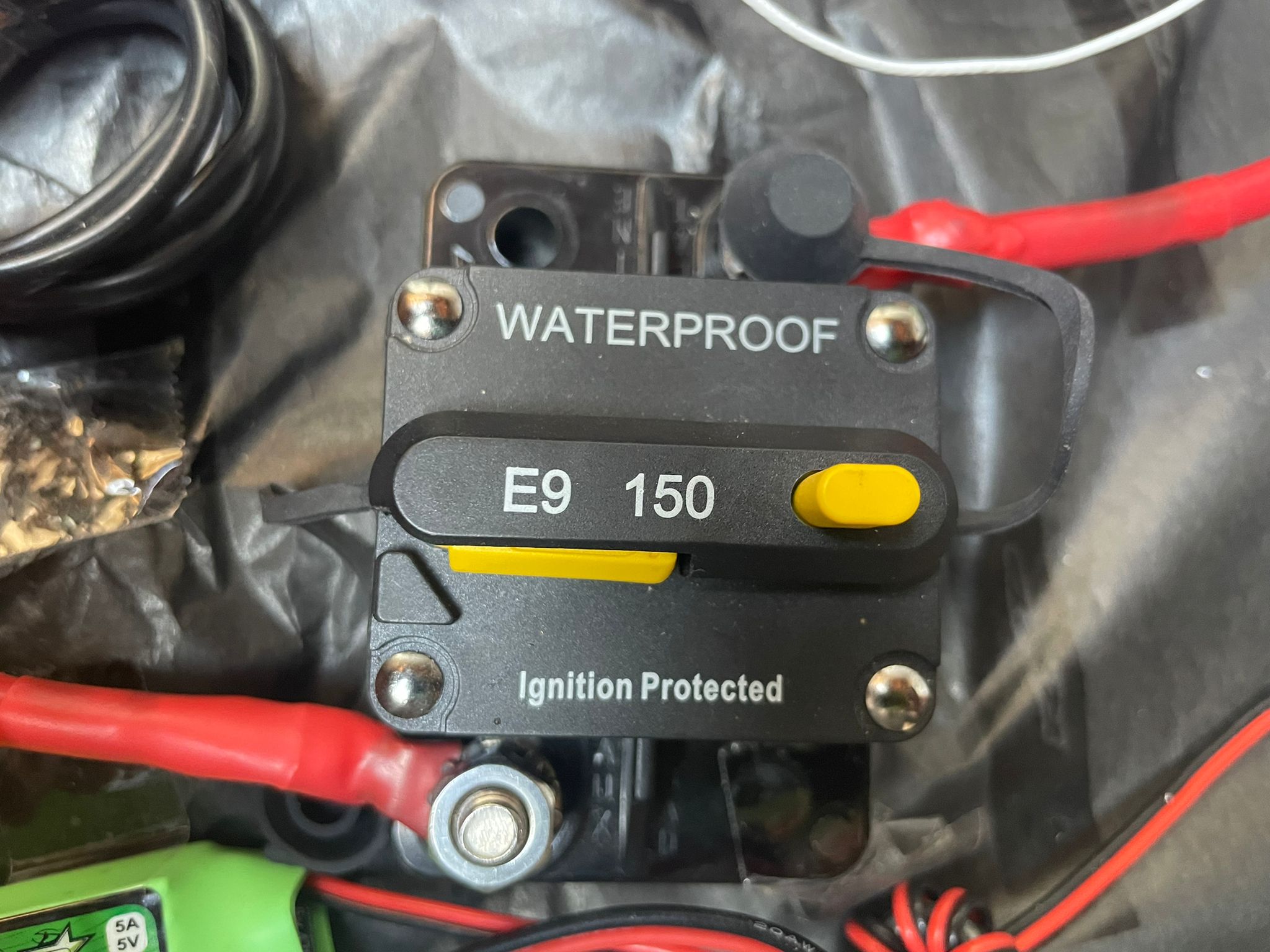
" When I start the bms it locks up when I turn it off you hear the kilovac release". If wired correctly believe the kilovac should be activated by the main switch, disregarded of BMS function? Can see a auto fuse of 150 A. Is that Blue Sea or other quality brand? If not, its probably a crappy clone doing more harm than good… you already have another fuse according to the picture?
Hi @XSailor thanks for the reply,
The circuit Breaker E9 150 I bought it on amazon but I never doubted if it was a clone. I unlocked the video is to be heard rather than seen, sorry  .
.
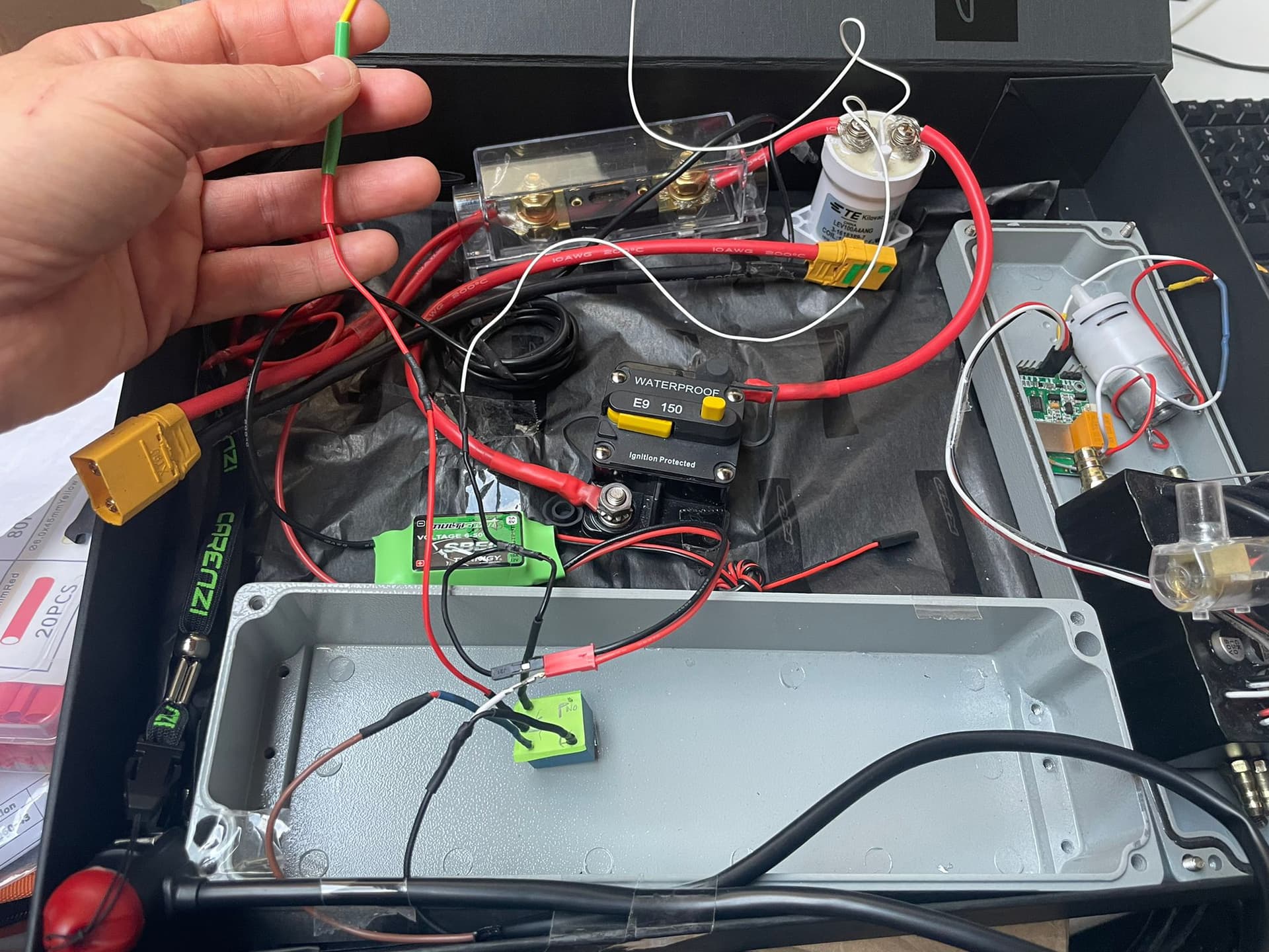
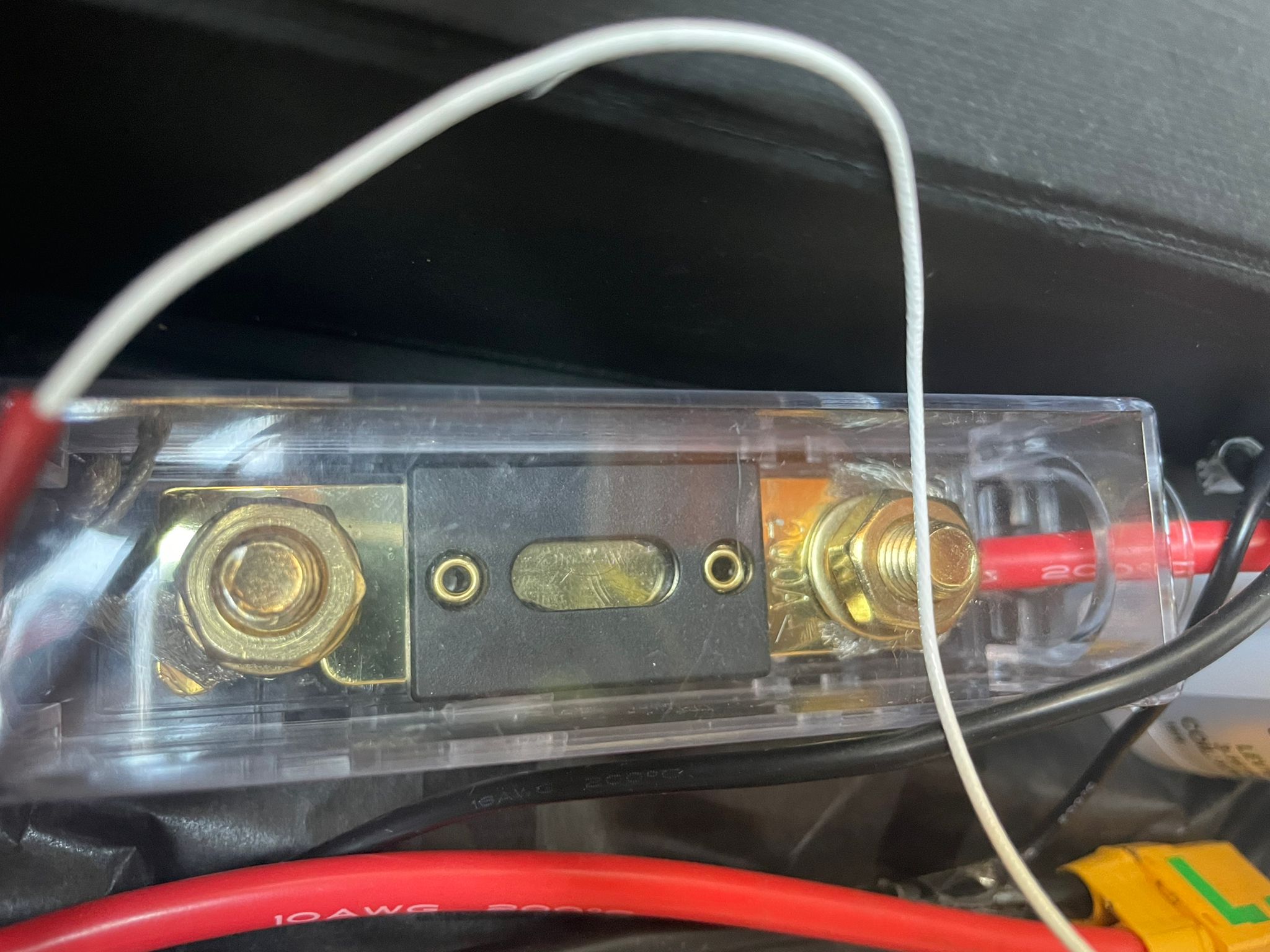
I am attaching another image, hopefully clearer.
@vib.dxb Thank you I’m glad you can help but it’s all thanks to @jeffM
tnks
Hi Andrea,
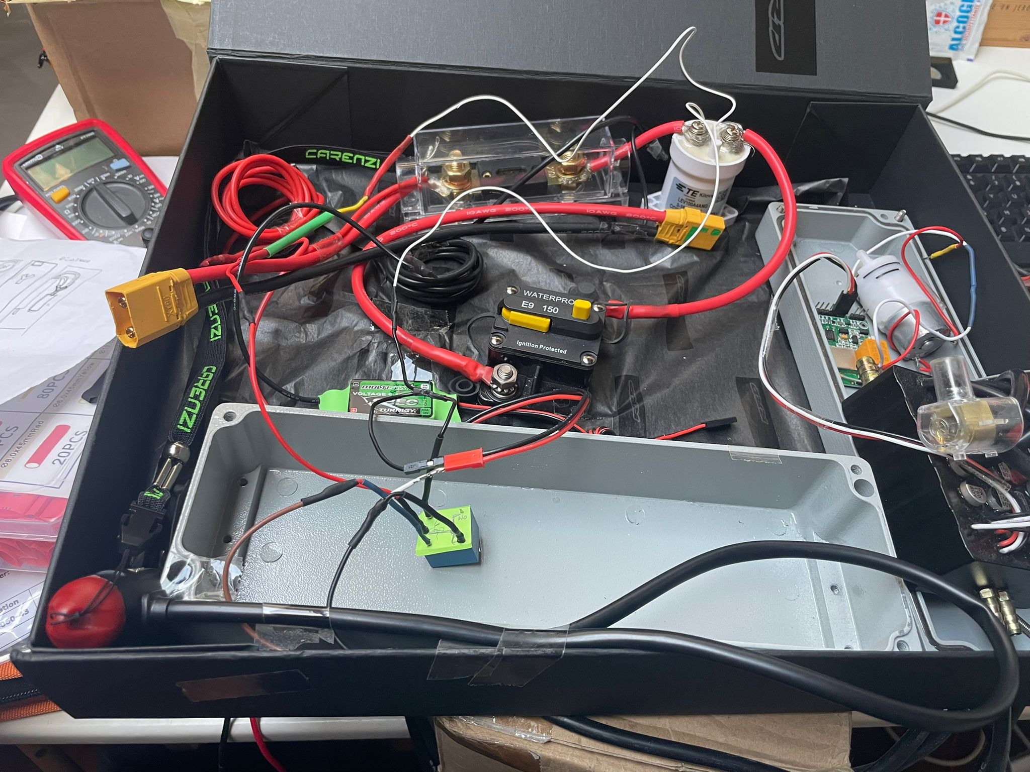
For help you on the troubleshooting, can you check the voltage here please :
and which battery and BMS you use
Thanks for the help @jeffM 
My bms is an ANT BMS h24S 100A, the battery pack is a 12S / 10P like your V3 project.
I forgot a premise, at the first installation everything worked, I disconnected to make the welds put aside and it doesn’t go anymore. I think I have replicated all the points but apparently not!
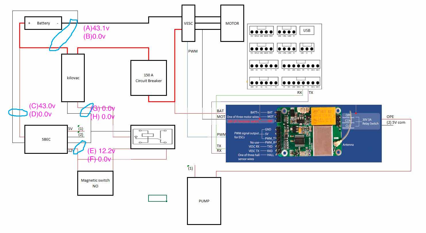
I checked the voltage as you asked, for each measurement by letter, I made a double measurement in the points you have rightly marked for me, the first without with the circuit connected up to the point the second with the circuit all connected, I also tried to replace the sbec with a new one and the SRD relays, it doesn’t change much. I suspect I messed with the bms app:
- (A) the disconnected battery measures 43.1v
- (B) all connected goes into protection therefore 0.0v
- (C) if I disconnect the SRd relay it gives me 43.0v
- (D) if I connect the relay then it does not go 0.0v
- (E) if I unplug the 12.2V SRd relay
- (F) if I connect everything then 0.0v does not go
- (G) I disconnect the SRd 0.0v relay
- (H) all connected 0.0V
thank you 
1 Like
Is your battery 100% charged?
if yes you have a problem with the BMS
if not it may be the relay
Do you have the 5V on the SBEC ?
Do you have a smart ant bms? If so, install the app on your phone, log in and see how it works.
1 Like
Hi guys, I’m still here to try and fix the problem.
I have charged the batteries still having problems
Going by exclusion I powered the circuit with the power supply and everything works fine.
So I focused on the drums as suggested by @jeffM and obviously on the bms.
I noticed that in the DIS MOS: I have the Pre-Charge Failure error.
Are there ways to best set this parameter in order to avoid the error?
@Anatoly will turn you the error screen on my smartphone
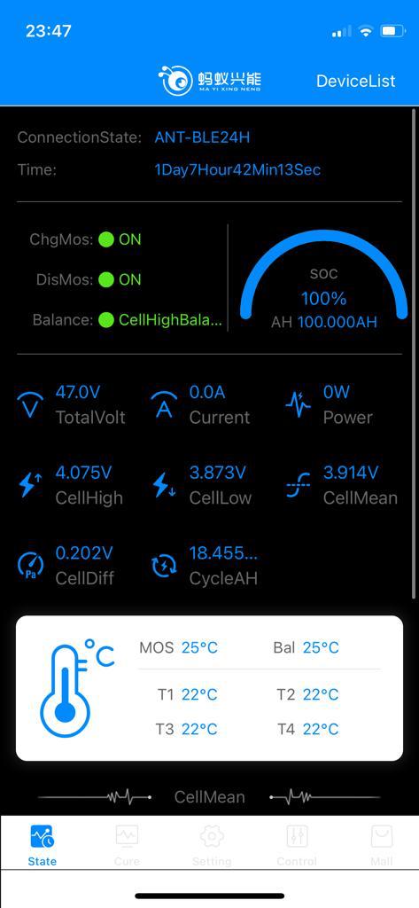
Without being connected to the circuit
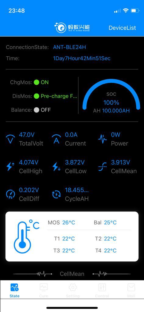
Connected to the circuit you can see the discharge error.
Thanks for your patience
I hope to be close to the solution.
In my opinion, you have a big voltage difference between the cell lines. 0.2A.Ideally, it should be 0.002A. Try using the app to enable balancing and leave it until it turns off itself.
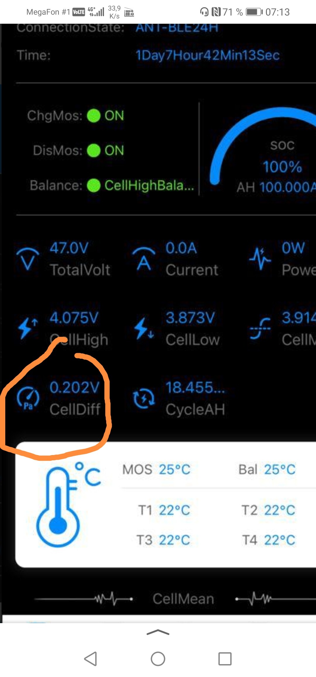
Get the balancing right first , 0,2v as said is too high, 10p battery with what 0,2A balancing charging ? may take some time like 10-15H …
And maybe more than a day!