That wouldnt be necessary for us if we make our own board and custom plate.
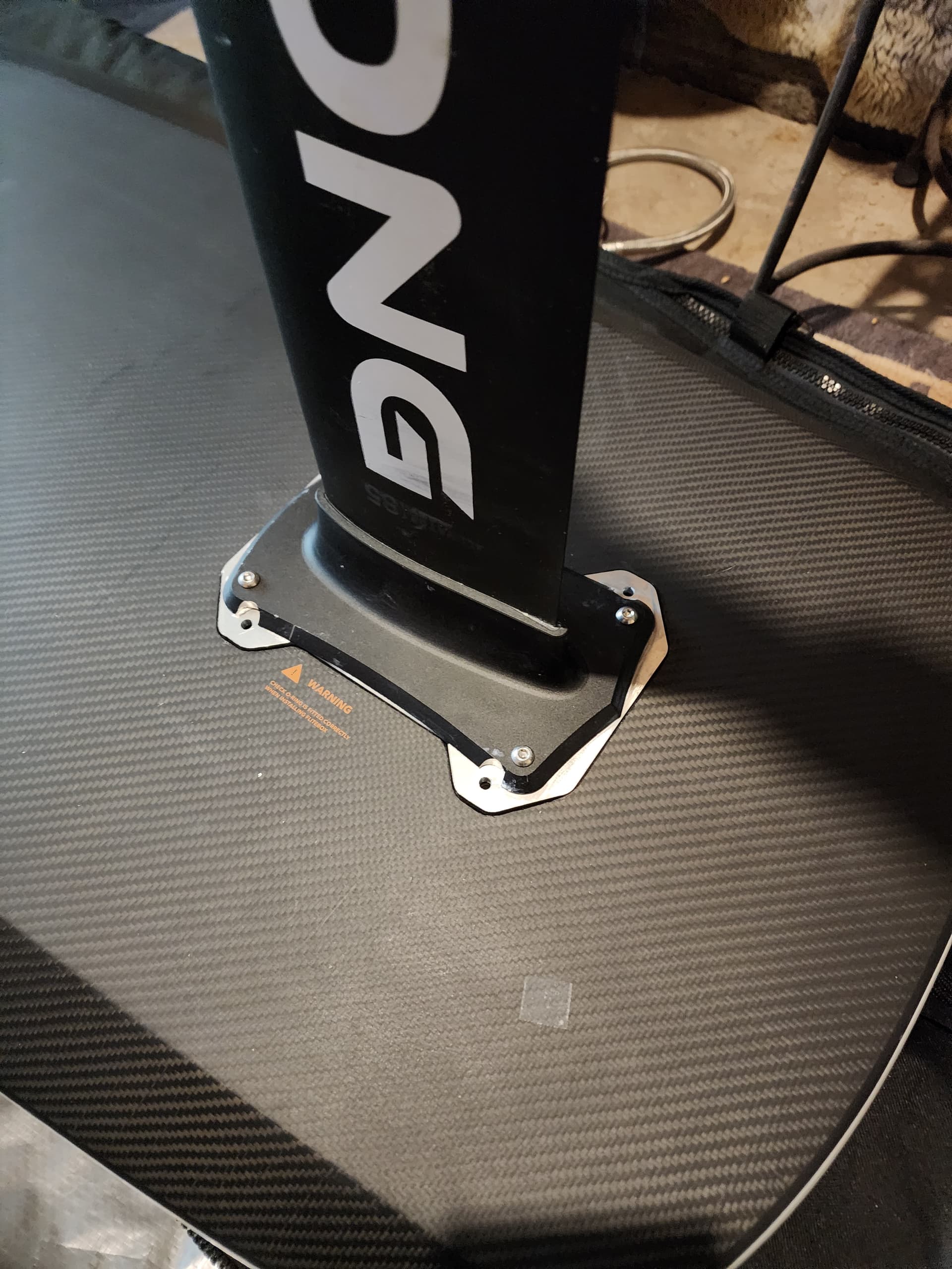
It looks like a conflict with the original fliteboard pattern due to the adapter plate.
From the pictures i can tell that they did that to tap into the thicker aluminium material in the middle of the plate. The original holes would probably line up at or over the step of the adapter.
Thanks for the links. The last one is really helpful. Thats some really good reference for my build. I guess i am not the only one who thought about submerging the VESC in dielectric fluid. I also read that people fill the motor with corrosion X to prevent it from rusting on the inside. I guess the 65161’s are not 100% watertight or condensate will build up in it over time?
1 Like
When using a Gong setup, the original holes from the Gong mast plate line about halfway up with the thick, and 1/2 with the thin part of the adapter, making it impossible to fix the mast plate tightly with the adapter.
1 Like
Thanks that makes sense. An all in one plate would be the holy grail I guess. Does anyone have a CAD model of the GONG top plate? On the other hand you would also need quite a big block of Aluminium that would be super expensive and takes forever to carve out ![]()
Yes that would be the perfect solution, but as you mentioned a big block of aluminium will be needed, and a lot of wasting it too.
I believe CNC pro’s call this “machining scrap”
Someone posted it here on the forum some time ago.
Update.
It can be found it this thread
Blockquote
Database for mast & plate
To be precise here:
Blockquote
Database for mast & plate - #127 by JvdZ
2 Likes
Its more like “Calculated Waste” you trade in more time and material for a less complex assembly solution without many mating surfaces. For an E-foil it will be worth it since you only really want to waterproof one surface at time and dont stack sealed surface upon sealed surface, if possible. Any watertight connection is a possible failure point and failure points can stack up quick.
1 Like
Yes thats true, but not sure if the effort is worth it. If we can drill a straight hole through the adapter plate into the mast plate, we can add some epoxy or a rubber on the inside around the hole, where the two plates meet and/or add some silicone on the outside of the plates.
I think thats the way I’m going to start chasing. A simplified adapter plate that lets me go straight down to the mast plate and waterproofing the two metal parts as good as possible
I am not sure if a straight hole will be sufficient. Epoxy and rubber do not bond well with the silicone phase wires!
That’s why most adapter plates for the flight boards have the extra “pocket”.
More silicone is better ![]()
1 Like
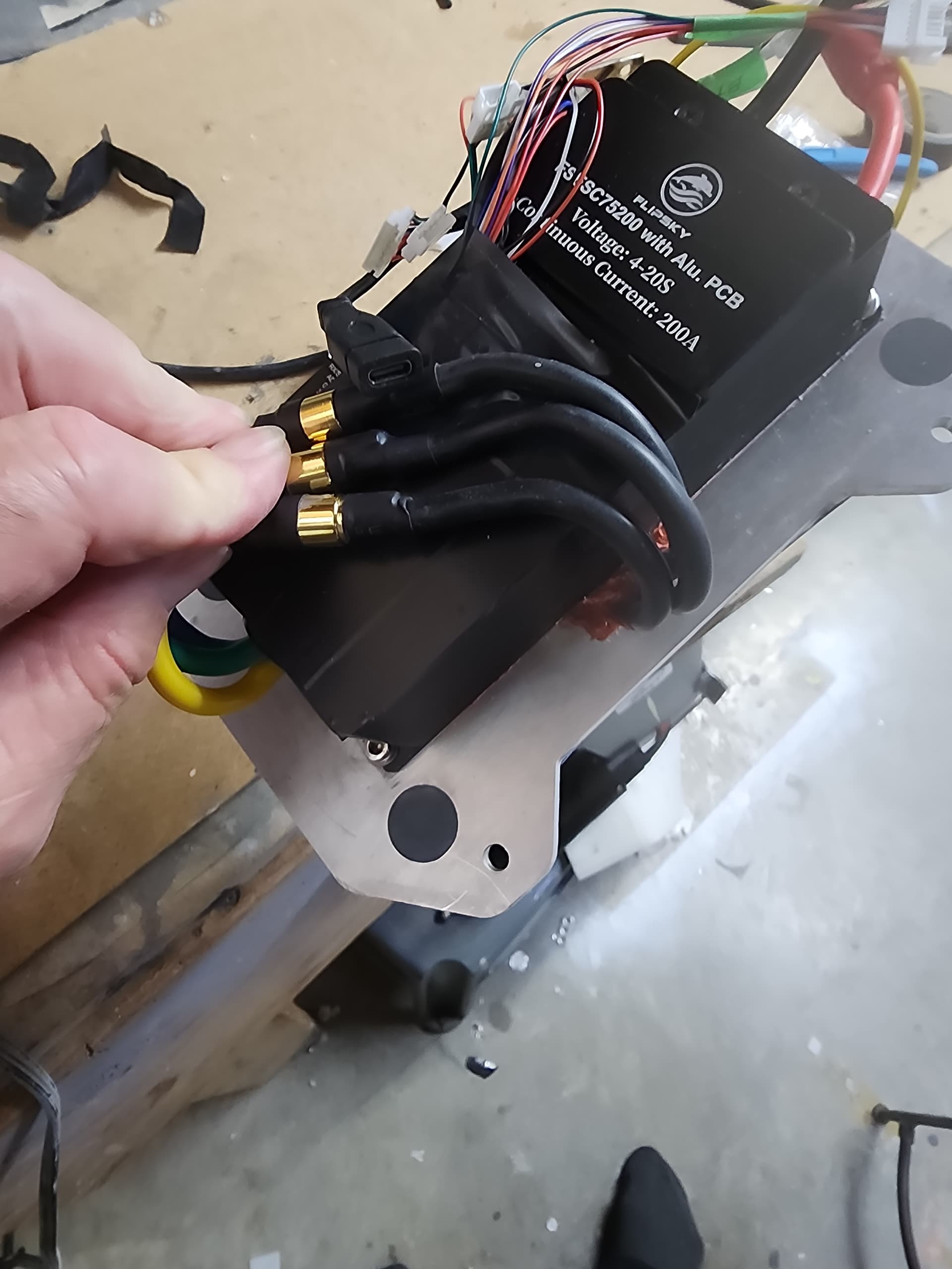
Another implementation of the esc on top of the mast is done by @EASYFOIL.EU. If you look around their Shop you can see photos of the various parts and a bit of how it’s implemented.
Just a reference point that is not based on a Fliteboard
1 Like
Ah, they seem to mount the ESC sucker directly on the mast plate in a waterproof way. I think I will try and model some stuff up with my limited CAD skills and then let you all point out my design flaws ![]()
It’s not possible to see exactly how EasyFoil has it configured. The tricky part is how the motor phase wires are routed since they come right up the mast in the center of everything. I suspect EasyFoil succeeds because their custom VESC is a long and narrow design and maybe it fits to side. You can buy their VESC separately if you want, so it could be an option
1 Like
Don’t underestimate the pressure of the water coming up the mast when the mast moves downwards. I had an esc mounted on a box directly above the mast. I used seals around the phase cables but the construction was not waterproof enough and the esc finally died due to water ingress.
1 Like
I made a simpler plate for mast to fliteboard.
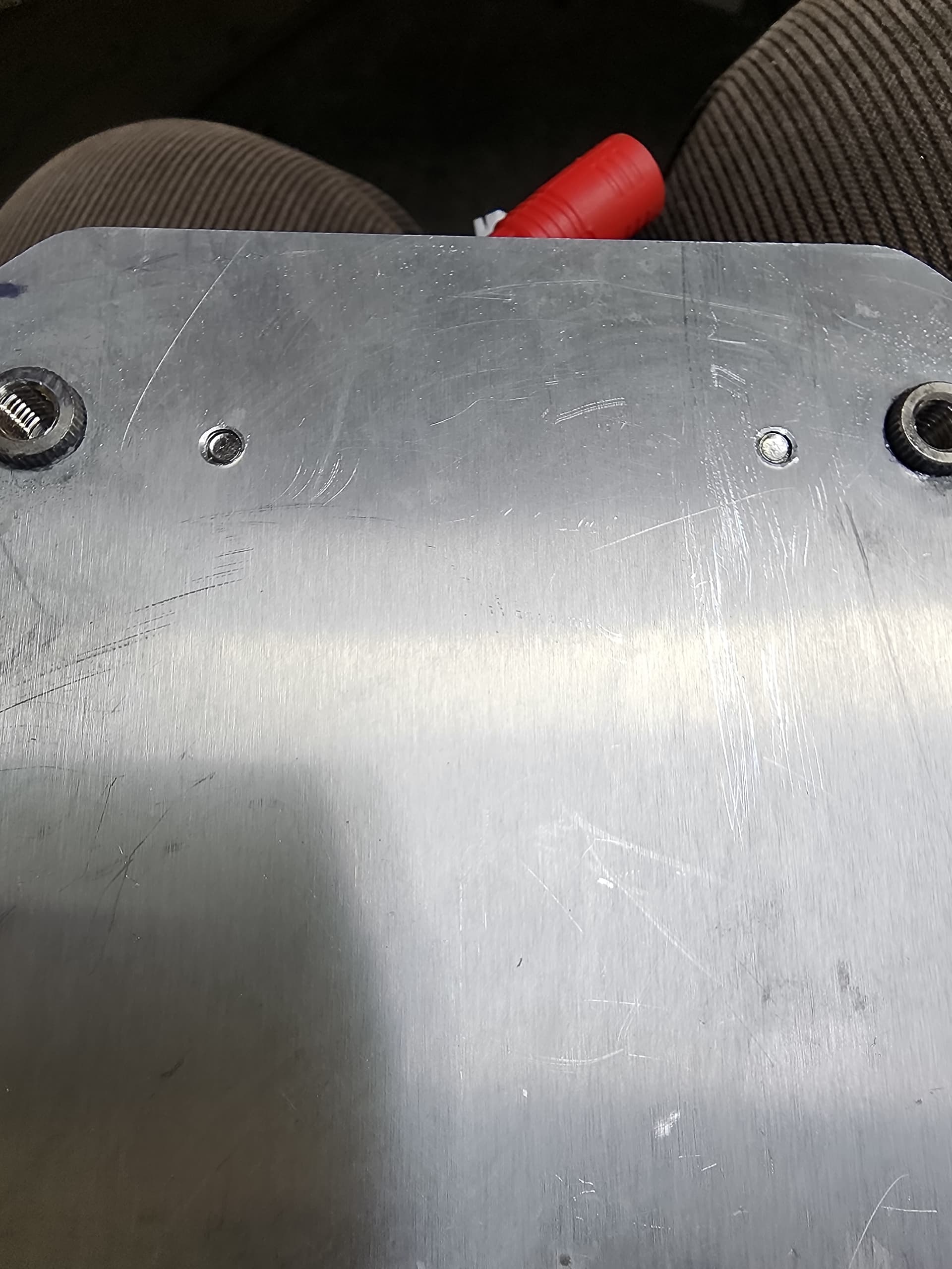
The inserts are stainless used for making snowboards. I have used it all this year no leaks.
Used JB weld.
3 Likes
These are the style of insert M6 blind end.
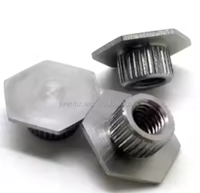
Saved a lot of machining waste and makes no need to drill those odd hoes on the mast base.
How many mm of threads do you have?
5 threads using the 8mm insert. I had to make holes recessed in the back of the gong plate. But I like the extra threads.
1 Like
Interesting to see another approach! So the JB weld is on the inner part of that hexagonal surface where it meets the adapter plate? I like that with this approach you were able to use the original holes on the Gong mast plate instead of needing to drill new holes on a thicker portion. I may adopt this in next build this winter. One possible issue could be galvanic corrosion developing since I think you have stainless inserted into aluminum. Probably not a big concern for you though on Canadian lakes
I see no corrosion. Since it is all gooped together with silicone I dont think any water gets in that area anyway. I will see some salt waster in October. Last year I noticed some white stuff on the surface of the parts but still no corrosion. I generally try and rinse with fresh when I am hatteras.
The Batterypack is coming together slowly. Considered many types of cell orientation and came to the conclusion that i will take this approach.
The final size for just the pack in the holder will be 250mm x 290 mm x ~75-80mm
It will be 14S10P and at 3.7V Nomial can hold 2072Wh
The cell holder for the pack is a custom 2 part 3D print. (2Top 2Bottom)
I can only print 256x256x256mm. The cell holder in one piece would be to big for my printer.
You can see the parting line in the picture where i split the cell holder in two. I chose a splitline for the two prints where its not only in X but also in the Y direction. This way the stress on the glued line is lowered when the assembly is glued. This way the pack can never just split down the middle in a straight line. (Theoretically) The busplates also overlap 1 of the splits on each side, they will add some strenght too.
Every Cell will be fused with 30A SFW Fusewire. Kinda like Tesla does it.
The copper busplates are not to scale yet and only placeholding dummys for now. The plates will be laser cut to a nicely fitting shape and siluette and will get a concentric hole over each cel. The Busplates will attach to the cell holder with a bunch of M2 nylon screws, the fusewire will then be spotwelded to both battery and busplate on each cell. I will most likely reduntantly fuse both + and - poles of each cell since it will be less work if i make laser cut plates anyway. Maybe i double fuse (30+30A SFW) each cell on the negative pole but im still not sure if that will be even neccessary since 30A is 30A no matter what.
I try to safe weight whereever i can.
In the end i decided against using 21700 Molicel P42a since i found the 21700 EVE 40P for alot cheaper. Not much info on the cell, only some russian youtube videos that looked VERY promising. I only heard good things about eve’s LiFePo4 280Ah cells so i thought i give the 21700 a shot. Especially for 2.95€ per cell.
The wole battery enclosure itself will be for another time, i will design my own which will most likely be 3-D Printed in 8 parts (4top - 4Bottom) then glued together and reinforced with fiberglassed to make it strong and sturdy. Not sure about the seal at the split surface or the bolt inserts yet but i will figure something out.