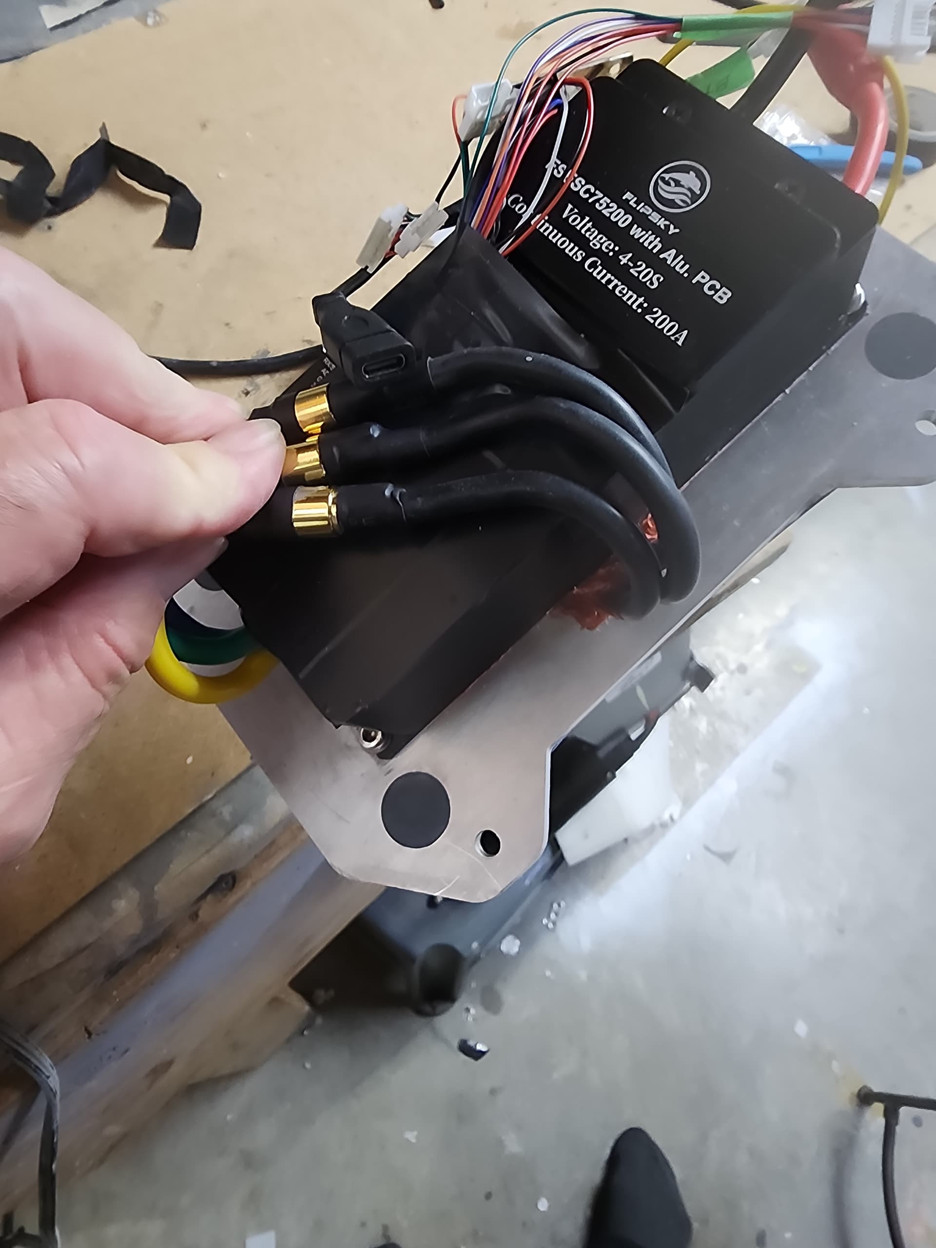
It’s not possible to see exactly how EasyFoil has it configured. The tricky part is how the motor phase wires are routed since they come right up the mast in the center of everything. I suspect EasyFoil succeeds because their custom VESC is a long and narrow design and maybe it fits to side. You can buy their VESC separately if you want, so it could be an option
1 Like
Don’t underestimate the pressure of the water coming up the mast when the mast moves downwards. I had an esc mounted on a box directly above the mast. I used seals around the phase cables but the construction was not waterproof enough and the esc finally died due to water ingress.
1 Like
I made a simpler plate for mast to fliteboard.
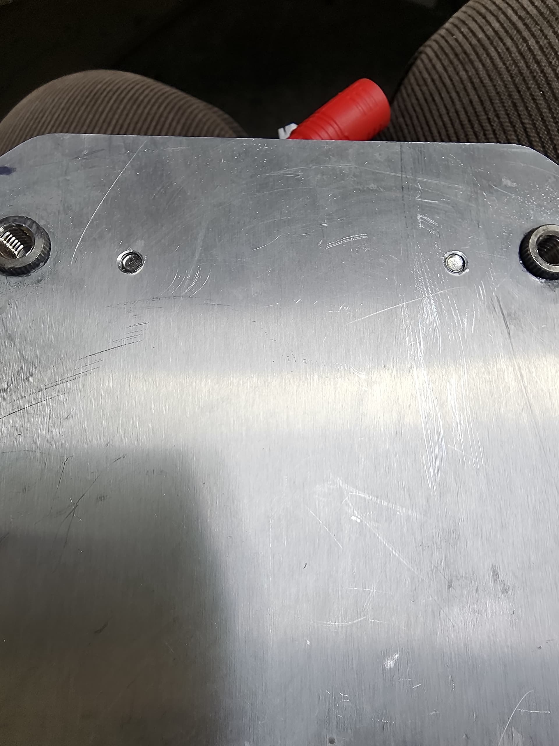
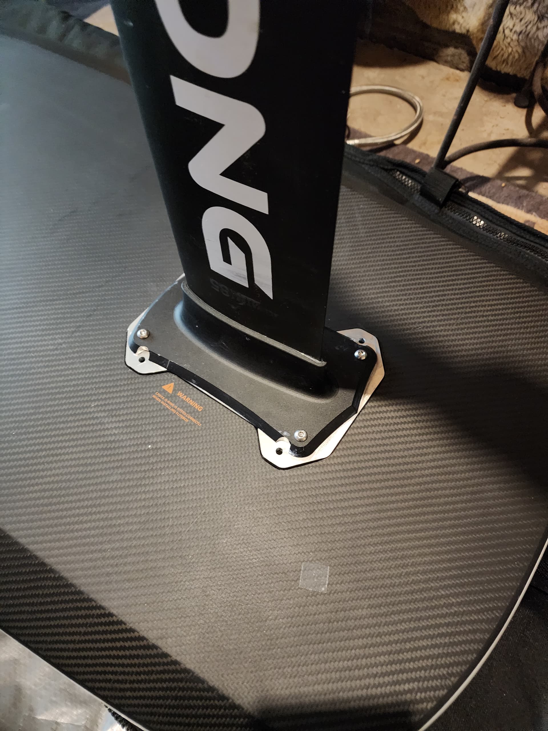
The inserts are stainless used for making snowboards. I have used it all this year no leaks.
Used JB weld.
3 Likes
These are the style of insert M6 blind end.
Saved a lot of machining waste and makes no need to drill those odd hoes on the mast base.
How many mm of threads do you have?
5 threads using the 8mm insert. I had to make holes recessed in the back of the gong plate. But I like the extra threads.
1 Like
Interesting to see another approach! So the JB weld is on the inner part of that hexagonal surface where it meets the adapter plate? I like that with this approach you were able to use the original holes on the Gong mast plate instead of needing to drill new holes on a thicker portion. I may adopt this in next build this winter. One possible issue could be galvanic corrosion developing since I think you have stainless inserted into aluminum. Probably not a big concern for you though on Canadian lakes
I see no corrosion. Since it is all gooped together with silicone I dont think any water gets in that area anyway. I will see some salt waster in October. Last year I noticed some white stuff on the surface of the parts but still no corrosion. I generally try and rinse with fresh when I am hatteras.
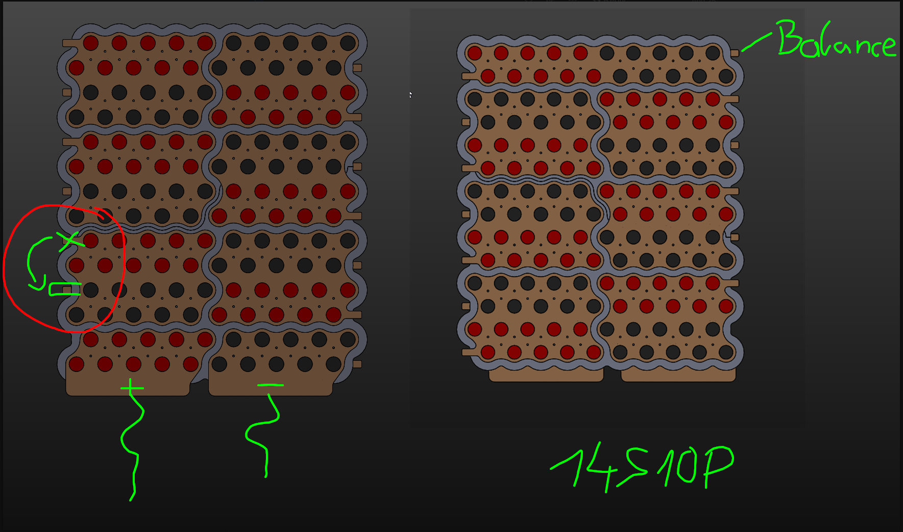
The Batterypack is coming together slowly. Considered many types of cell orientation and came to the conclusion that i will take this approach.
The final size for just the pack in the holder will be 250mm x 290 mm x ~75-80mm
It will be 14S10P and at 3.7V Nomial can hold 2072Wh
The cell holder for the pack is a custom 2 part 3D print. (2Top 2Bottom)
I can only print 256x256x256mm. The cell holder in one piece would be to big for my printer.
You can see the parting line in the picture where i split the cell holder in two. I chose a splitline for the two prints where its not only in X but also in the Y direction. This way the stress on the glued line is lowered when the assembly is glued. This way the pack can never just split down the middle in a straight line. (Theoretically) The busplates also overlap 1 of the splits on each side, they will add some strenght too.
Every Cell will be fused with 30A SFW Fusewire. Kinda like Tesla does it.
The copper busplates are not to scale yet and only placeholding dummys for now. The plates will be laser cut to a nicely fitting shape and siluette and will get a concentric hole over each cel. The Busplates will attach to the cell holder with a bunch of M2 nylon screws, the fusewire will then be spotwelded to both battery and busplate on each cell. I will most likely reduntantly fuse both + and - poles of each cell since it will be less work if i make laser cut plates anyway. Maybe i double fuse (30+30A SFW) each cell on the negative pole but im still not sure if that will be even neccessary since 30A is 30A no matter what.
I try to safe weight whereever i can.
In the end i decided against using 21700 Molicel P42a since i found the 21700 EVE 40P for alot cheaper. Not much info on the cell, only some russian youtube videos that looked VERY promising. I only heard good things about eve’s LiFePo4 280Ah cells so i thought i give the 21700 a shot. Especially for 2.95€ per cell.
The wole battery enclosure itself will be for another time, i will design my own which will most likely be 3-D Printed in 8 parts (4top - 4Bottom) then glued together and reinforced with fiberglassed to make it strong and sturdy. Not sure about the seal at the split surface or the bolt inserts yet but i will figure something out.
Design looks nice. The individual cell fusing is a nice touch but does make for extra work. Also I believe most cells actually build in a kind of fuse already on the positive side.
I did cells level fusing on my first pack build, but didn’t have a fuse on the main battery lead. Earlier this year I was messing with a second hand VESC (bad idea) that wasn’t behaving and using this pack. The VESC somehow had a complete failure and shorted the entire battery pack. This instantly blew almost all the cell level fuses at once. Now I the entire pack will need to be disassembled to conduct a post mortum inspection of all the cells. Probably will never get around to this. It might have been spared if I had a fuse on the main lead.
So, don’t skip a big fuse on the main lead!
2 Likes
Thank you for your insight! Really sorry to hear that you lost your pack ![]()
I forgot to mention it but the packs cell level fuses should theoretically blow at 300A I already have a 250A and 200A fuse for the main leads sitting on my desk. i will include this fuse on the Positive connector side where the pack will supply the VESC.
i dont know if i can get away with the 200A Fuse with the 200A VESC. The 65161 is limited to 120A via the datasheet so if i set the VESC to 150A max ist should be fine, i hope… Maybe a 150A Fuse for extra safety?
About the already in place cell fuse you mentioned. Isnt that only correct for “protected” cells. I never took a dead 18650 apart so i dont know. I dont know if these or most standard cells have a fuse inside, correct me if im wrong.
I think 150A and 200A are the normal size on these diy efoils. At 14S I think a 150A fuse is probably plenty of headroom.
I’m really not certain about the built in fuse on some battery cells and how common they really are, maybe I shouldn’t have mentioned it. I had seen someone post about it in a forum I think (not sure if it was here or not). I don’t think I’ve seen specifics about this from cell manufacturers though.
1 Like
Nothing to worry about. i just found a topic in another forum discussing the same thing. Somebody mentioned that fusing is not needed because most cells have a so called “CID”. Short for “current interupting device” I don know if that is true for all cells and neither did the people in that forum. Somebody made a really good point.
Quote:
“There are several examples on here (and youtube) that show that a fused cell is a good thing and saved not on the packs, but potentially the building.”
Endquote.
Another Quote:
"The biggest reasons:
- I do this in my home/garage not in a manufacturing plant. so fusing large battery packs can prevent any accidental mistakes. I don’t want a venting battery going off in the house.
- some don’t use industry standard/best practices at times which increases risk.
- When you’re tired, you make mistakes, and when you make mistakes, you can ruin a whole pack or in my case because I fused it, save a whole pack"
Endquote.
I will go ahead and also fuse all my cells. Every layer of safety is good in my book. If i burn my cell level fuses because i miscalculated something or the fusewire is garbage i will learn from it and still can use the same cells after the error is fixed. I also really like the idea of fusewire. Im probabably way quicker at replacing cells if i ever have to, simply snip 280 times with a cutter and the whole thing is loose again and comes apart. Nickel strips take longer to remove and damage your cells if not careful. I will spotweld the wire so the workload isn’t that much more over the nickel strips. If anything its strain on the eyes and your fingers. ![]()
1 Like
I use a midiOto 200A fuse for my build, works fine with vesc limited to 125A Battery current on 14S. In my first build I had a 150A fuse blown @12S but that was with a Flier ESC without current limitation capabilities.
If you need more information about the eve 21700 cells, ask in the german speaking Telegram groop, I think some people there uaed them (there are differen types though).
Molicel 21700 P42A are really good, not much drift after 3 seasons, less voltage sag under load than the Samsing 40T.
The cells we use aren’t protected by a pcb but with CID built into the top, this is acting like a fuse on the plus side. problem is that these aren’t 100% fault proof in paralleled packs. Cell level fusing is a good thing ![]()
3 Likes
The Battery Brick is coming together nicely. Still waiting on the 60A Daly smart BMS for the finishing touches since i dont know its exact dimensions yet. I hope i can start printing the Cell holders in a couple days when the BMS arrives.
Since i will lasercut the Copper busplates anyway i included a solder flag for every positive terminal. Those can be folded down after assembly of the pack to route the BMS’s Balance wires neatly around the pack and will safe some space in terms of pack height.
The Bms will get a different separate Waterproof connector on the Battery Box for charging only.
Discharging will be straight out of the Battery main leads and will be fused with a 200A Main fuse.
1 Like
Just one thing, it’s good practice to take the balance lead out on the negative side since the entire cell can is negative, lower risk for shorts (even though this is minimised anyway with good holder design)
I actually never heard about this. I know the whole can is negative up to the crimped top.
Do you mean instead of running them pos to pos from neg to neg on each parallel pack? I never seen anybody doing it like that. Does that even work when the BMS in that instance technically sees -V instead of +V since polarity of the Cells from the viewpoint of the BMS is reversed? In the end one positve terminal is needed anyway at the beginning. Maybe i think about it the wrong way. But if i measure a cell from pos to neg in correct orientation it shows +Voltage, other way around it shows -Voltage
Or do you mean running it like this on every series connection?
In my config or any config i dont see what would change about the protection from a short because of the bms wires. Its still reading potential against Battery-
I think i know what you mean since if it reads negative and is routed alongside the shell of the battery its the same potential and wouldnt short. I would have to flip the whole bms from pos to pos to neg to neg then.