yes, in a series connection the side meeting negative pole and the side meeting positive pole on the plate has the same potential so you can take the balance lead out on the negative side of the plate.
Do you happen to have a link to those? Aliexpress would be ideal, since i’m not from the US.
Thank you
I looked into Fuses and was quite shocked what i found. The Range on common Megafuses is quite wild and the manufacturers often produce completely disatrous fuses. I know the ANL/Megafuse Types are delayed thermal fuses and will heat up at the limit until giving out, but some models went way past that and were not even close to the ISO rating of 1.35x A for 2-30min
From what i’ve seen your 200A fuse could blow from anywhere between 200A up to 300A or even 350A. Incase of a real Battery short (Important for Cell Level Fusers) or miscalibration in the VESC that would be double the continous limit of a flipsky 75200. (Burst rating is 300A but who knows if it could take the 300A for 1+minutes?)
Most megafuses including some more expensive brands failed these Tests on multiple Videos i found.
I have no proof and i highly doubt that every test i saw was performed under ISO Standards or was really representing something of real scientific value.
BUT, i will look into Fast Acting Fuses or MCCB’s after seeing that.
TLDR: I suggest looking into Megafuses a lil more for the whole community. In my cell level fusing Case the Cell level fuses give out at 300A (30A x 10P) and a 200A or 250A Megafuse would most likely not blow first. Meaning you would need to rip apart a pack and replace the broken Cell Fuses.
1 Like
As a battery builder the tip I would give is that this design is well thought out and planned, could work if you had someone stance or cute these out, I would however reccomend having it be a layer sandwich where there are round cut outs and what you would theoretically weld to each individual cell is a 0.2mm piece of nickel.
Where the nickel and copper is welded before welding the cells, or even better just make it out of 0.2mm Nickel entirely because I’ve tried with my rather good K-weld setup to weld copper like this and it just wont do in my experience while nickel welds just beautifully.
Do you mean lasecut the fuses in place like the design which battery hookup supplies? I was not planning to spotweld the copper directly to the cells. The Copper Busplate will be connected to the Batteries via 30A Fusewire on each Cell. The Busplate itself has a thickness of 0.5mm so welding that would be a nogo.
Do you know at how much amps the Nickel strips with 0.2mm and X width let go?
I chose copper over nickel Busplates since lasercutting them takes the same time but the internal losses of pure copper are much smaller than with pure nickel. This should also help keep the pack cooler since the overall resistance will be lower.
Do not waste time with fusing each individual cell thats an extreme hardcore work that probably lead to more issues than benefits in anyway, besides it taking probably more than 10x as much time to complete, besides 0.5mm copper is very thick I would probably never go beyond 0.3mm and in this design I would just make it a nickel sheet since you have such high parallel setup and individual nickel strips for each cell.
If you want to fuse anything fuse the battery pack itself at 100-150A and around 0.2x8mm can probably hold 30A continous with acceptable heat, but since this is a 10p config that would be 300A per parallel group which is an impossible amount to pull on a e-foil, probably your solder would melt or battery connectors would desolder themselves.
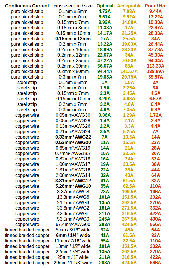
See the chart below for round about numbers for what you can get and you can note these are continous currents not peak, you will never pull that high peak on a battery so its really nothing to worry about.
1 Like
I chose the Thickness of the copper at 0.5mm so its easier to cut on our laser. 0.2mm or 0.3mm is very wobbly and warps all over the place from the heat while cutting. Thinner than 0.5mm is a PIA to keep flat when cutting.
But yes i aggree, according to the chart 0.2x10mm nickel strips would act as a last resort fuse in itself. That would also be an option.
I just chose the fusewire approach since it would be a neat look like tesla has and incase of a breakage of a fuse its an easier fix and much simpler to cut and remove all the wires to replace bad cells. I would still choose to lasercut the busplates just because its hassle free and doesnt look like a complete mess of strips going all over the place.
FYI i also just bought a K-Weld and im not soldering anything on this pack besides the main leads and balance leads. Which will be done before i start spotwelding to keep heat from the cells.
The fusewire should work nicely when spotwelded both to the cell and the busplate but i will test it out first. It will be more time consuming yes.
I also had on my mind what really happens when a cell shorts and melts the fuse completely. A fusewire will ideally form a bead on both ends and just simply disconnect, while a big 10x0.2mm strip has a lot more material and could form a molten bath of nickel that “theoretically” keeps shorting in the “Cup” shape between the positive button of the cell and the inner negative casing of the cell until the metal is literally vaporized.
I will give both ideas a shot and think about it
Seen this table before on esk8. i don’t think it is good since there is no mention of the accepted heating and what the strip length is assumed to be. After all, batteries can have 30mohm resistance per cell and the comparably minor strip resistance because of this gets less important.
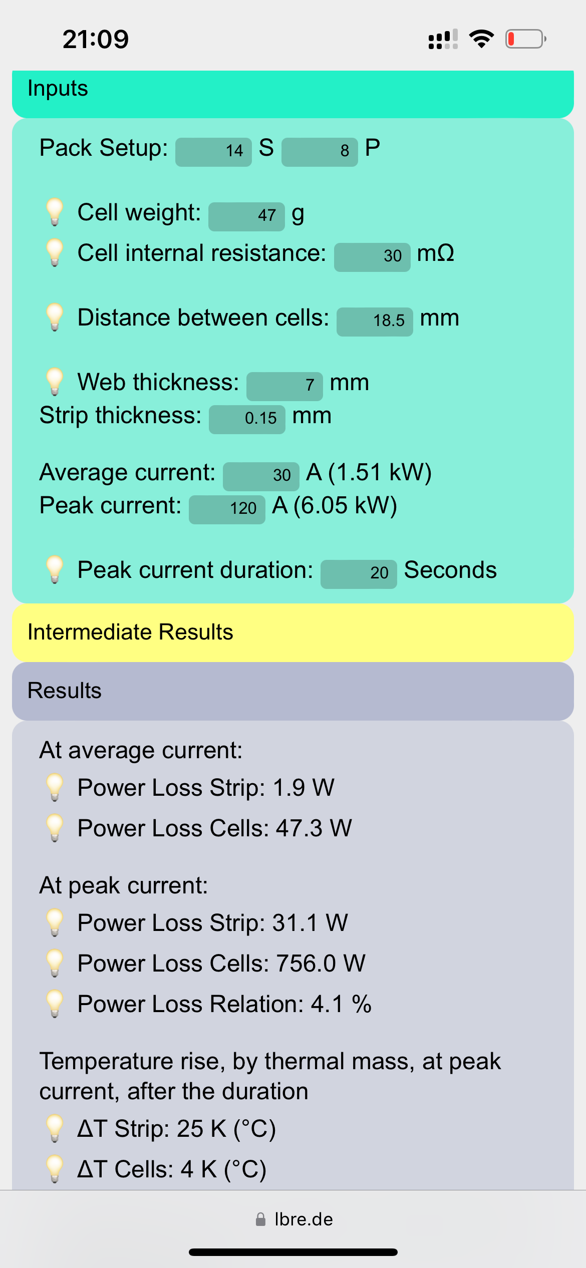
Check ludwigs calculator here for a better tool:
https://lbre.de/hp/BPC/BPC.html
I just want to inform you, there is no single cell in the market besides some extreme Lifepo4 high discharge ones that can output peak 120A that can actually even have a chance at melting 0.2x10mm nickel, so no it wont fuse.
Because nickels melting tempature is 1455 degrees celsius and there is a reason fuse wire so thin, your cell would desintegreate before anything would happen there, the rating above is saying it will reach 80-90 degree celsius at 38Amps continous uninterrupted which is unnatural, 21700 cells cant output enough Amps to even make it budge on their own.
The fuse wire setup Tesla works really well because they have such massive battery banks that the load per cell is actually fairly low and even though a 10p is a fairly large battery fuse wire is just too low peak rating for our use case, it should be something like 10A or less per cell, I think the ones Tesla used to use was like 3-4A fusing.
And in my experience if you have something go wrong with a single cell its usually the end of the entire parallel group and even if it would fuse burn instead, then you would get a underperforming group that would kill itself as its wearing unnaturally and it just makes the individual fusing pointless, as that group would drop below safe voltages faster as they are missing a cell or cells and charge faster and it would be a vicious cycle.
Since it seems its your first build, I would just reccomend get some scrap cells, do practice runs, skip the individual fusing just stick a 120A fuse on the positive terminal and go from there, keep it simple, you will need to learn alot of planning with fish paper and kapton between series and silikone and balance cables planning will be a bigger challenger than anything else.
1 Like
Thank you, i will check the calculator out right now. I have a internal resistance meter in the mail so i cant measure the resistance myself at the moment. Accorrding to Russian Youtube The EVE 40p tested at around 9-9.5mohm.
But just a pure strip connection will be hard to calculate with this since it turns into a criss crossing and double layered mess really fast. Making for a uneven thickness across the pack with different thermal absorption and material thicknesses.
This would be eliminated with equal lenght connections in a laser cut busplate design.
Instead of just cutting holes and using the wires i could cutout kind of a strip over each cell opening that just has to push down and be welded in place
Thank you for your elaborate answer i will consider doing a “normal” build but my heart still says stick with the cell level fused design. I dont want to protect the pack on the cell level against motor or VESC overcurrent. I want to protect and isolate the cells from themselves incase one has a malfunction or gets shorted. These cells have 50A peak but on a dead short the 30A SFW (Standard Fuse Wire) should definately blow.
The main fuse attached inside the case on the Pos terminal will be for simple overcurrents or battery shorts but the cell level fuses are piece of mind and last resort.
Since you mentioned the nickel strip will never even give out and act like a fuse this means there is 0 internal pack protection and one cell could runaway to the point where you have a literal toxic smokebomb in the trunk of your car. 30A Fusewire as integrated in my original design could disconnect the malfunctioning cell. Of course against internal shorts inside a cell there is literally nothing you can do and the pack will runaway with or without fuses.
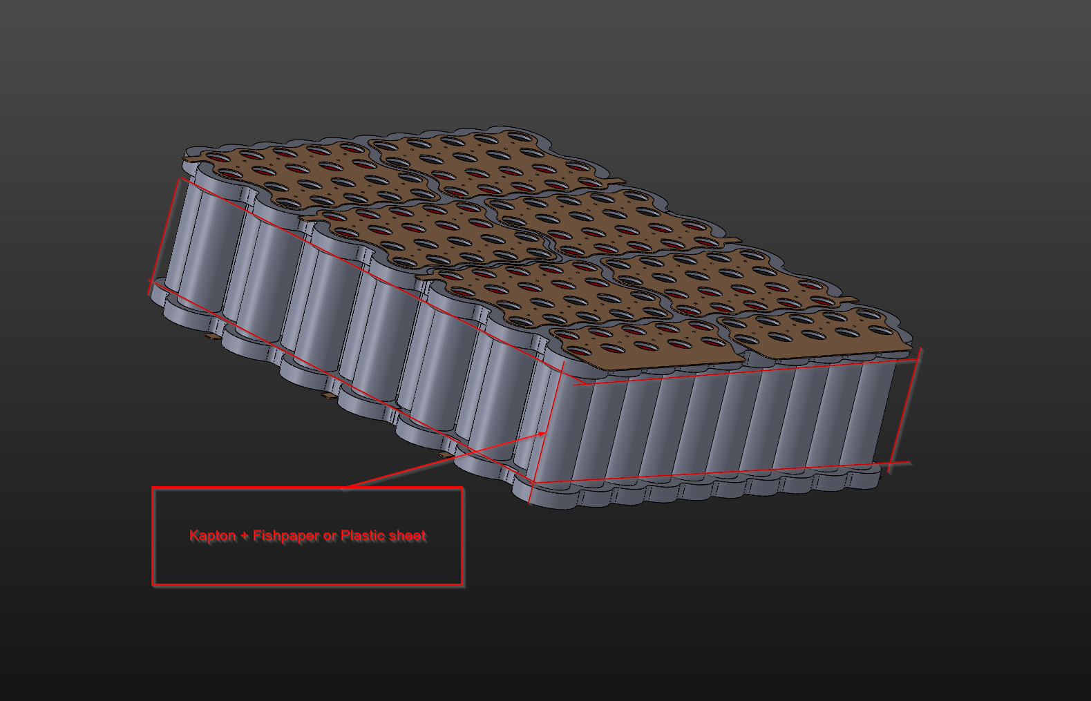
Fish paper or thin plastic sheets will be used in this design only where its needed. I will wrap around the whole pack with kapton after assembly and multiple different layers of kapton will hold the balance leads in place and isolate them from the cells. On the sides and in the front where the leads run along the casing of the battery and the BMS will sit a thin sheet of plastic or fishpaper will ensure separation from the cell housings.
I mean from my experience with around 22+ battery builds my very subjective experience and with the battery failures you usually see 95% of the battery fires with Li-on cells seems to stem from shorting between series and usually with prior cell damage and high state of charge.
Li-on can be volatile but it is not nearly as volatile as Li-Po packs are, I have done all sorts of bad things when building packs from simple mishaps of shorting with nickel tabs, welding at too high current etc. and from my experience usually nothing happens if its a single cell taking damage, as long as the outer wall is intact.
Only time you see your life flashing in front of your eyes is if the series make a short circuit and you have 4-8 cells working together to make fireworks and there is a nickel to nickel short, then there is enough energy to make things go boom for, thats why good series seperation and protection is important, this is also why it takes one cell to go super sonic and the heat from it damages nearby cells and it goes boom for real.
But if there is such severe damage to the cell, the fuse probably wont prevent much, but either way I said my two cents and you can do as you like and what feels best for you of course, I also think there is a reason Tesla stopped the individual fusing of cells in that way, I also think they used to do that with a laser welder and not spot welding but I can be mistaken!.
1 Like
I did some more digging down the rabbit hole about pack design and reflected on my whole project idea in the meantime.
It might have sounded like i was not really straying away from my starting design and that i was hardset on my idea.
Which is not the case.
I just want to let you know that your input and experience is really helping me out and after giving it some more thought i will most likely go for the standard method. Just sticking nickel strips on these suckers, fuse the main lead at 125-150A with a megafuse and hope for the best. I got enought engineering to do on the battery case, vesc housing, mastplate and the DIY board already. No need to fully prototype a new way of manufacturing battery packs or reinvent the wheel for every new part.
You made some really good points. I will most likely still use my copper busplate design since the materials are already here.
Instead of Fusing with the wire i will spotweld 0.2*7mm nickel strips from the busplate to the cells. Not as fuses but just as a permanent connection.
Sucks that i bought two rolls of 30A fusewire for 80€ that i probably will never use. Atleast i can still test and fiddle around with those if i want or maybe use them eventually on something else.
I also read up some more about tesla style fusing and many sources mention that they actually never saw a single broken fuse and incase of a SHTF runaway they wont matter anyway. The only time they would save you is in a series short like you mentioned. But there would need to be some substantial manufacturing flaw/error or force involved where one busplate moves far enought to short to set of a dead short to the next plate. (If we rule out human error like dropping a strip)
I wil redesign the busplates so they will accept a strip instead of the fusewire.
But before cutting anything i should test if i can actually weld the strip to the copper.
If that wont work ill use pure strips or get a 0.2mm nickel sheet and cut single sheet busplates that can be welded directly in place.
Thanks for your help ![]()

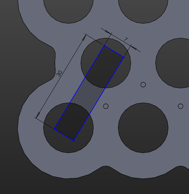
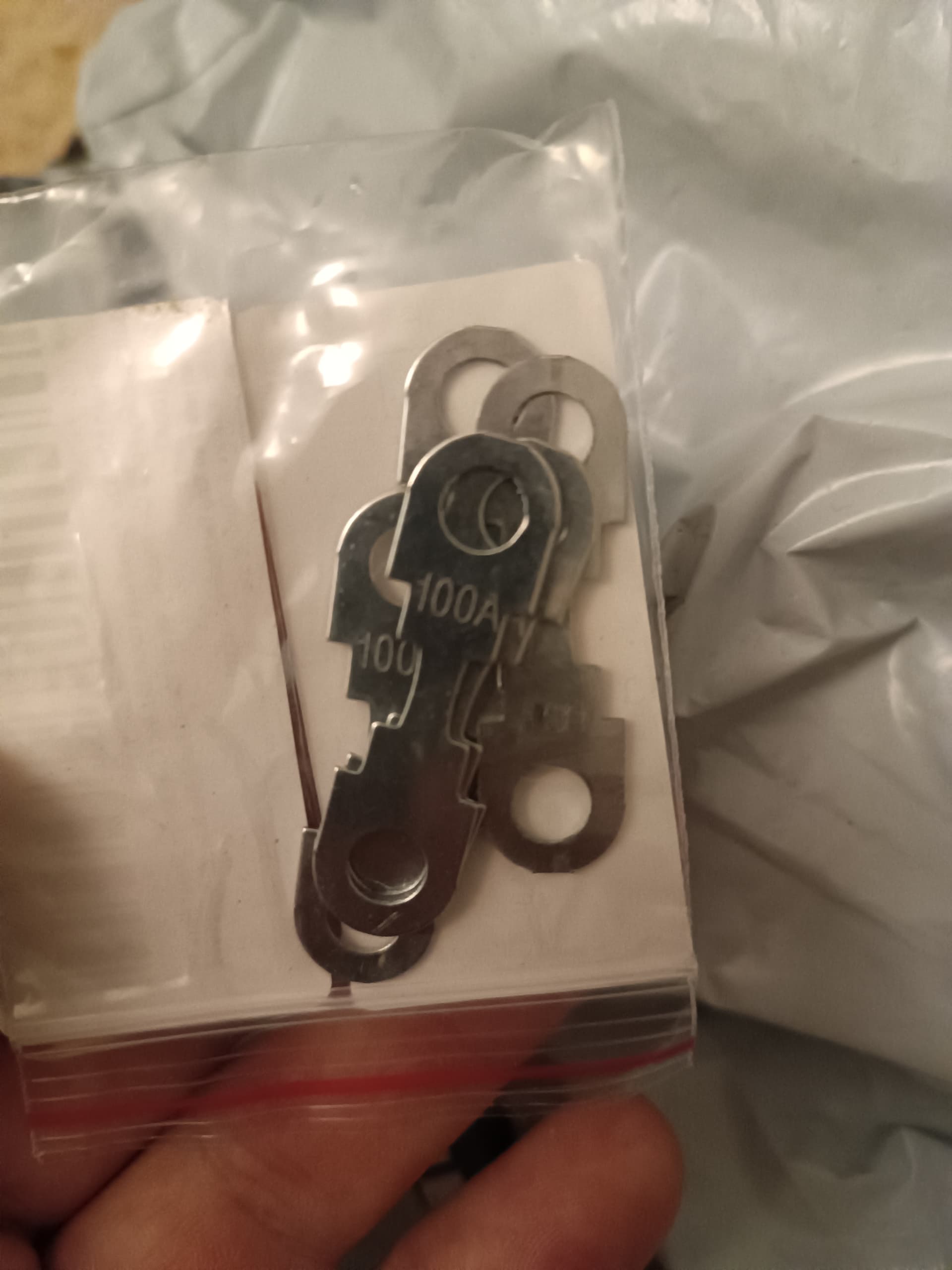
if i adjust the holes with these flat spots shown in red it should offer a good edge where the strips could bend down nicely. Sadly i cant seem to find a supplier with 0.2x7mm or 8mm strips in stock for now. But i saw that nkon has these precut 30mm long 0.2x7mm strips for nearly the same price as buying per meter.
I adusted the spacing from the top of the cell to the bottom of the busplate to 0.5mm (2mm before). Now I will use fishpaper stickers on the positve poles of the battery for more insulation since the spacing of 2mm before was plenty. I moved the busbar closer to the cell so the nickel strips bend down more easily
I just built a pack with a copper nickel sanwich. Maximum copper thickness I was able to spotweld with kWeld was 0.15mm copper but this needs a lot of energy with kweld (around 150J). I used 0.1mm copper with 0.1mm Nickel on top. Welds with 80J with kweld. After 30 welds the electrodes got too hot and I had to make a break.
The pack works well so far.
What kind of power supply are you using with your k-Welder? I have some old tattu 4S 1550mah lipos that i could wire in parallel to make the welder more flexible and portable. I do also have a good car battery that i could use but it would be rather heavy to move around on a desk due to the wire lenght
I use 2 Hobbyking Turnigy Graphene 3S 5000mAh in parallel, they are allmost too capable, if I fully charge them I get overcurrent (>2000A). If I charge them to 3.9V I get 1900A:
Car battery should work as well. There is also a capaictor bank available from keenlabs, if you want it lighter.
I also had a 4S in the beginning but 3S produces less sparks.
Take it from me a single car battery is not enough Amps, Li-po setup is nice and simple but can get very hot, however from my testing you need two car batteries in parallel to have enough juice, otherwise a PSU and the capacitor bank works really well.