How is the FDGen2 waterproofness ensured at clamp level between nose (or tail) and main body ? What’s the principle behind it ? Close-up pictures welcome.
I’d 3d print a mold and make a thick U-seal using gasket silicone, but TPU printed seal in 95 ish hardneds should also work from what I understand?
Edit: Looking at your alu case opening I’m thinking that it would cut and split the seal if clamped
Hi I am also interested on how to waterproof Li-ion battery pack. It’s hard to find some info on this. I was thinking a mold of PU foam bi component but how does it perform with heat ?
Options I know include mg chemicals thermal epoxy, natural cure silicone (marine type - not vinegar/acid), potting silicone, normal epoxy, glue + vacuum bag (kitchen souse vide type, seal over outgoing silicone cables),…
All options should resist 150C+ afik but resulting weight and application complexity varies. Durability…? Thin epoxy is heavier and less risk of air pockets, thick silicone harder to get tight?. Vacuum can perhaps be used when potting with silicone?
Battery design should ensure limited heating to avoid puffing. Potting at right room humid/temp cant hurt either.
Thanks for the detailed options on heat-resistant materials and application insights - will help me to get deeper on this.
I intended to pot with electronics silicone the ends of the cells including nickel.
But now I intend to only double heat shrink the whole battery + put glue between the heatshrink and isolating paper at the end. Watch my build.
The special feature of electronics potting silicon is thermal conductivity.
This thread is such a great resource! The countless hours on this forum gave me the confidence to start my own build even if I have no previous experience in such projects. I have started ordering parts for my build over the past few weeks, including 24 Molicel P45B batteries that I plan to use in a 12s2p configuration.
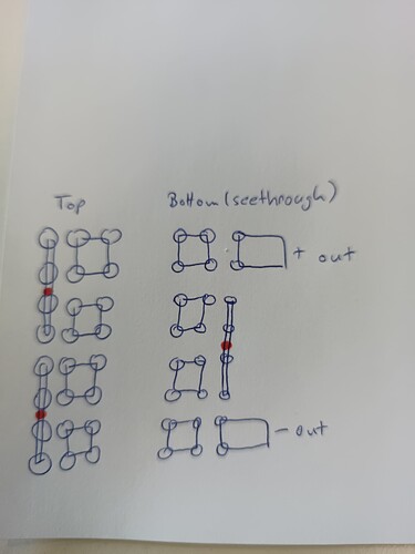
However, this will result in a 26 cm long batterie pack, which I find a bit awkward to fit in an assist case. Could anyone tell me if there is a straight forward way to physically arrange the cells in a 8s3p configuration, but to weld them so they are in 12s2p? I think I have a rough idea, but having one of you help me with this would be very helpful.
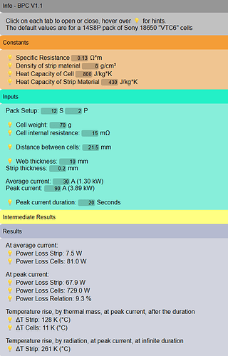
Also, I have used @ludwig_bre Battery Pack Nickel Strip Calculator to help me decide on which material to use for my pack, but I am not 100% sure how to interpret the results. Would using the steel strips with nickel plating sufficient? I cannot find the pure nickel strips at a reasonable price, but don’t want to create a bottleneck or a dangerous situation to save a few bucks either.
8/3 you can connect like this
Make sure to pay extra attention to the areas with red dots, they will see a lot of current, so make them at least double what the rest is
Regarding result of the calculator: The strips heat up to more than 250°C above ambient, that is way to hot! You need more (thicker) material for the strips for sure
Also be aware the cells you chose are only allowed to be discharged with 45A if you monitor the temperature and keep it below 80°C
Thank you! I will go for pure nickel then, and also double the thickness of all my connection. The calculation indicates that this should result in a strip ΔT of 30 C, much more reasonable.
I used the maximum rating of the cells for the calculation, but I hope I will be able to use a lower maximum discharge current. Very good point about the temperature and the need to monitor it, I will keep that in mind.
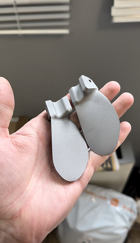
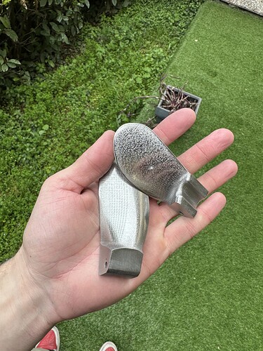
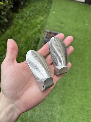
Stainless steel 3d printed folding prop
RAW
After 1h of sanding and dremel polishing
I paid around 30€ each at: Online 3D Printing Service | Custom 3D Printed Parts - JLC3DP
This is an affiliated link, we both get some extra discounts
Those they should brake ![]()
Expensive 3D printing, heavy stainless steel, post-processing required. What are the advantages over milled aluminum?
I like that 3 blade foldy. Is there a file you can share? How much did it cost to have that done?
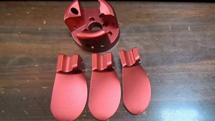
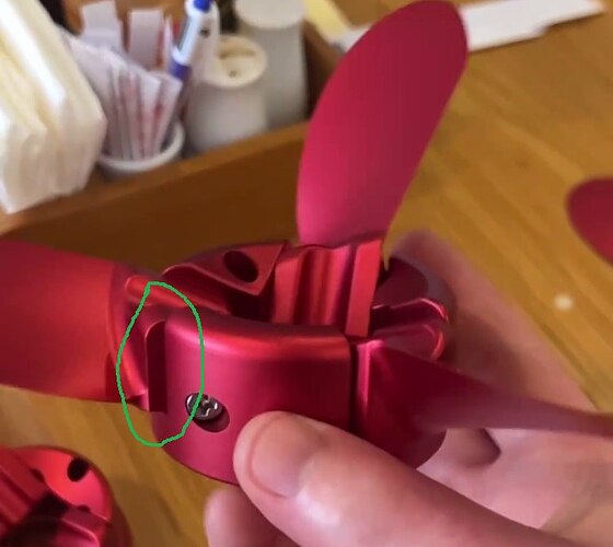
Unfortunately, I can’t, this is not my photo. And I don’t like this propeller because the Chinese found the blade model on the Internet and started installing it without thinking. This is what their base looks like). I published the photo only as an example.
They look very nice and clean, I was sending my files for cnc, but was more expensive then made them from steel, so I did that
Wow, these must be heavy.
THANK YOU @okp … the lead on the matek bec to power up the receiver with 5V saved me so much heart ache with the Flycolor FlyDragon 150A…
Before I mess it up can you point me to a simple wiring diagram for the the BEC?
Building a 12s3P and using a flipsky vx3 remote/receiver and came up one wire short…Gen2 faux drive
Is that alu stock? Thinking similar design with 12s3p 1st build and still in early stages. Was debating if a sealed 3d print over the pack could be sealed and fit in there perfectly. I’ll look for updates on your design
thanks! but credits are for my friend @Etiennebzh who discovered the HV3 & the Mate BEC !
It’s super easy. The BEC acts like a voltage reducer. You wire the GND & 5VIN from the ESC (battery side) and you wire the 5V OUTPUT to the receiver. You must absolutely verify that output of the BEC is 5V with a multimeter.
Quick photos of my Faux Drive included in the board
Yes, the aluminum tube is stock 80x50x2.
I’m working currently on a 3D printed 12s3p 2 rows battery spacer frame.
Then I will work on a cover on each side of the aluminum tube. The plan is gluing a TPU frame to the tube and pressing the cover against it using a strap. The door will include a waterproof connector to the motor.
Though the tube box will be waterproof, I am still sealing the battery and potting the electronics.
Hi @rttn & @seagull_nz
Love the print. I’m on thinkverse and only see one file. Can you point me to the .stl for the handle? TY
