Thank you for taking the time to compile the information to make a DiY FDA in a synthetic and orderly fashion. I’ve just rediscovered the following link that allows to determine the three important constants of any brushless motor:
The speed constant or velocity constant (Kv)
The no-load current (Io)
And the motor winding resistance (Rm), also abbreviated Ri (internal resistance)
The page then leads to: http://www.drivecalc.de/ : D-calc v3.4, a drive calculator, and PropCalc v3.0, a propeller calculator designed for air models but with adjustable
rho (air or water density) that allows to compare the efficiency of different rotating blade sections in water
chord: 9 chord sections are allowed from root to tip
angle: 9 associated blade angles. You may also enter a blade angle adjust value, thereby skewing the blade and thus changing the pitch within certain limits. @Bzhwindtalker so, following your question, this is a calc that could well be useful to efoil needs
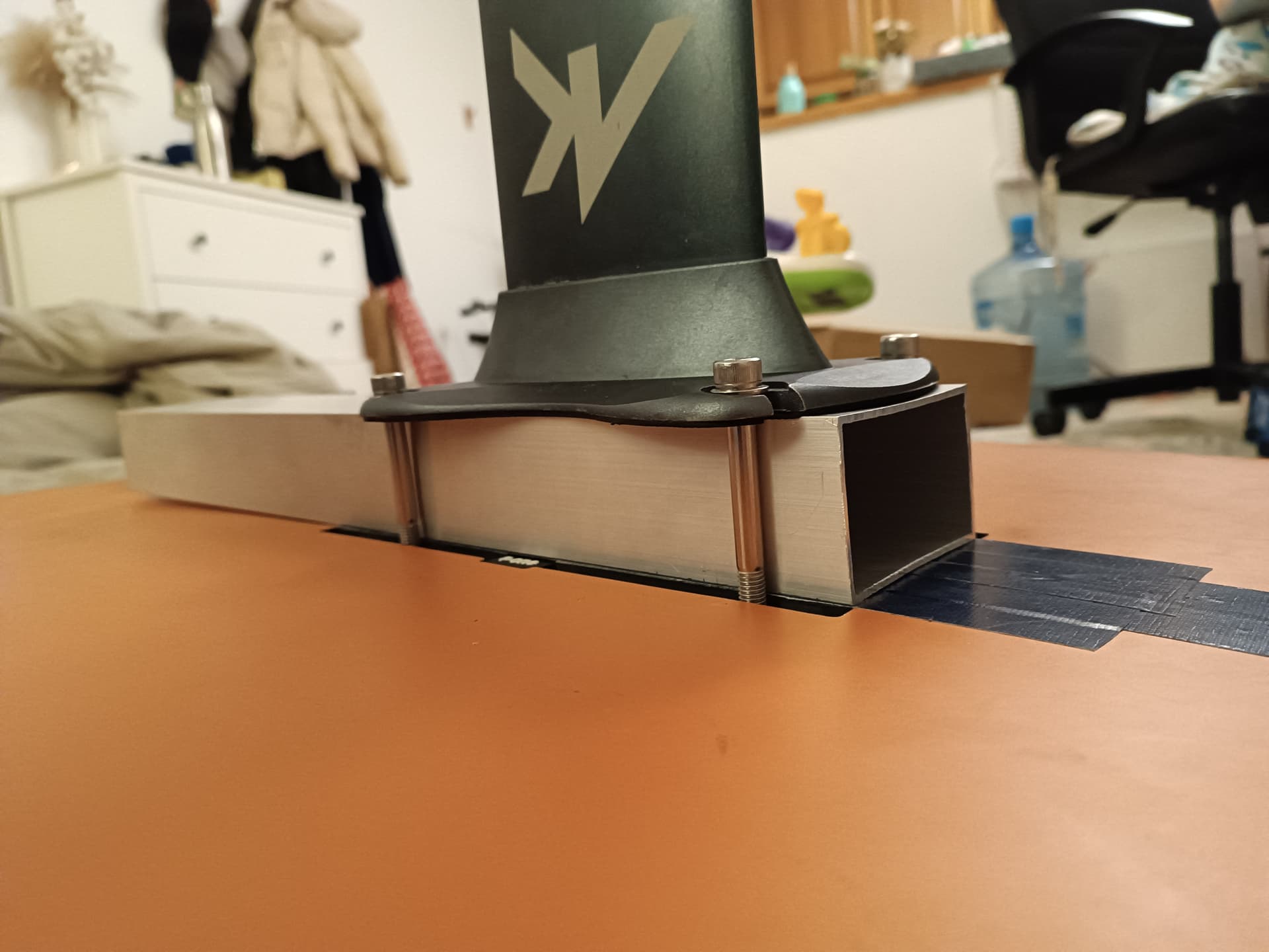
Transferring the load to some 3d printed spacers would solve that and increase rigidity.
Make it the shape of your base plate and go over/under the alu tube.
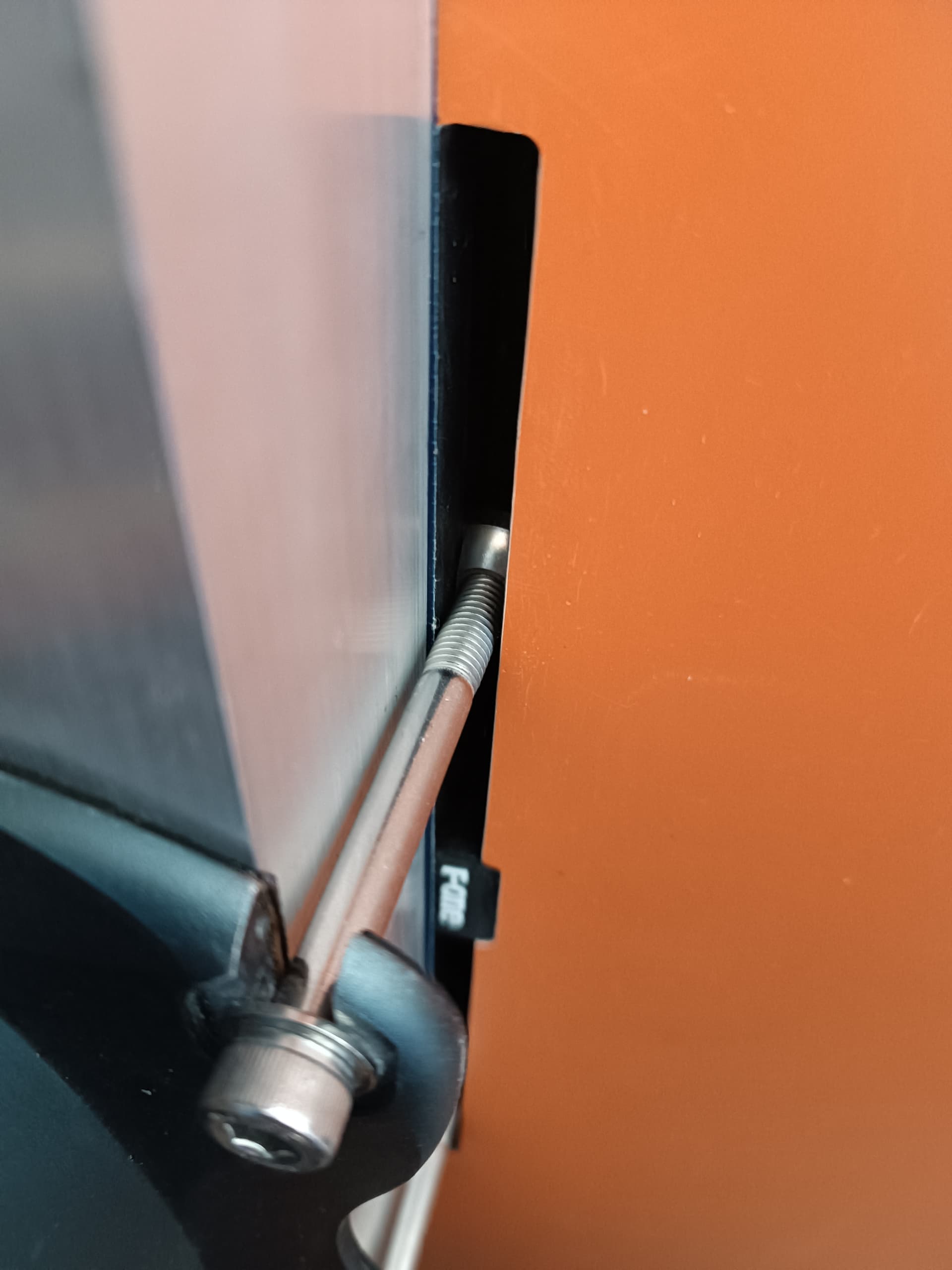
I think it was overtightened. And I moved now the base plate away from the edge.
Horizontal deflection of each side 0.25mm.
Vertical deflection of top/bottom 0.5mm (partly because of the tape under).
Is this a lot? @Foilguy@windego
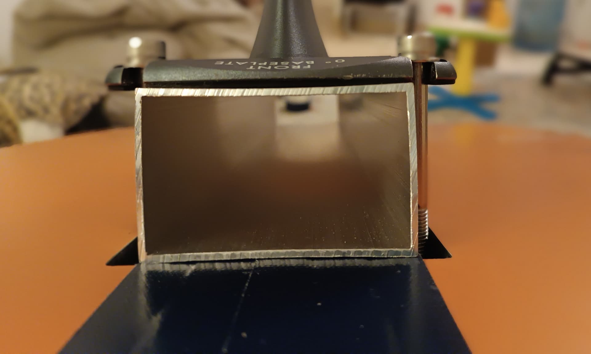
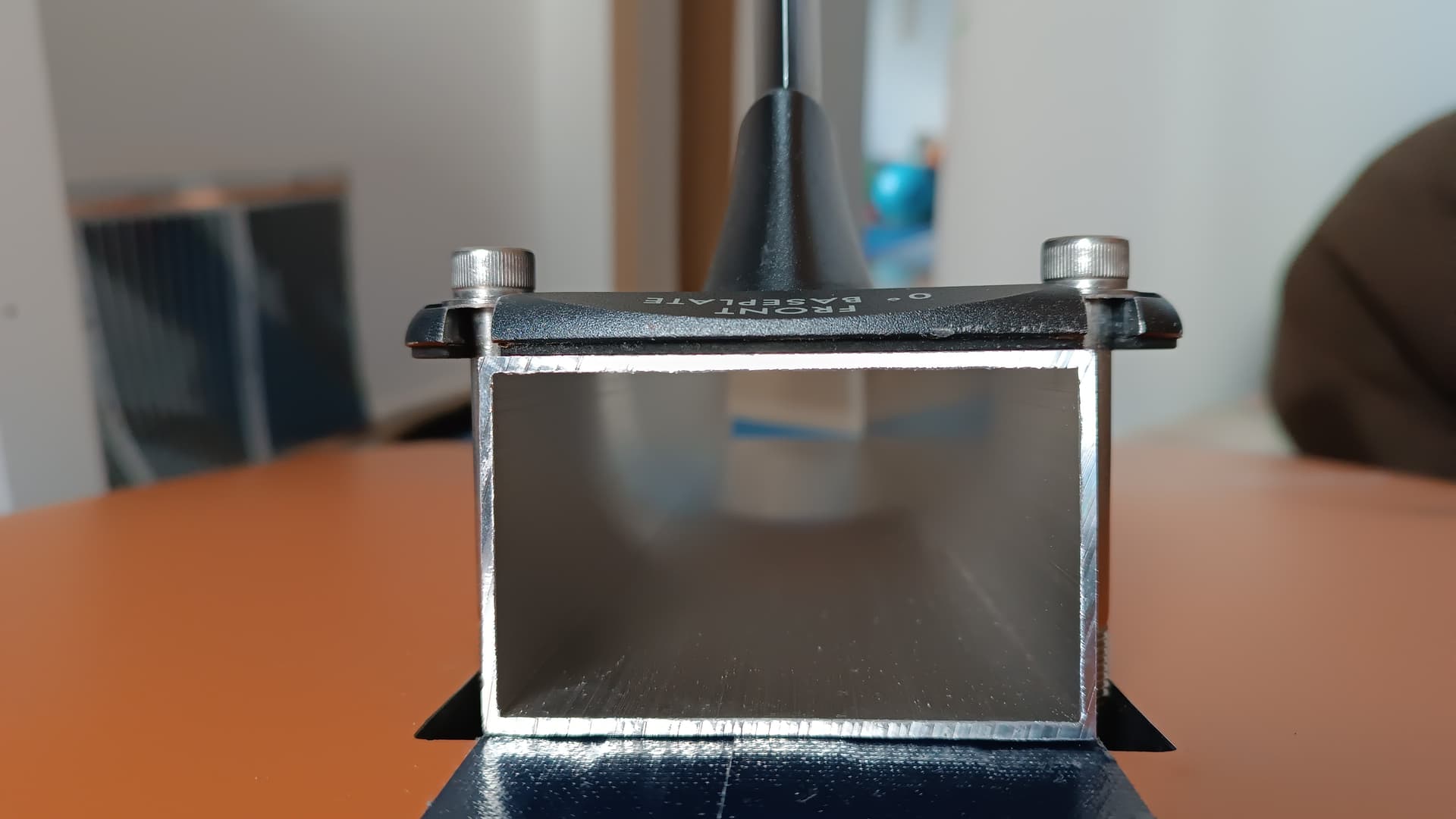
@Bzhwindtalker it seems to me that the walls are deflected. I doubt that adding plate on top and bottom will help. I do have many thoughts of reinforcements, like putting spacers around the screw - but I will have to cut into the box.
I would worry that the aluprofile collapes under loads during foiling. Even more concerned would I be about the mast plate breaking around the screwhead.
If there is any wiggle play in this mount it will be really no fun to ride. I had a tiny play in my mast section into the plate that made the ride feel wobbly. I epoxied it solid and it felt good after that. I suspect this setup will not be sufficient as is.
Each of us have to make decisions during the build process that we hope will result in a solid trouble free system when we ride.
You made a decision(s) about the box you are questioning about. A number of people have indicated a concern that you might not achieve a “solid” result.
You have proven to yourself and us that by simply tensioning the retention bolts you can deform the shape so you are already aware that the current box has the potential for a catastrophic failure.
Riding a board where the drive/foil system “wobbles” or “flexs” is challenging to control.
If you are riding an efoil is calm water with very little turning that wobble would likely be minimal compared to ripping it up in the waves on a foil assist. You have yet to ride the rig so you have no idea how much flex it will have.
If you are determined to use the box as a component housing I personally feel that it would be prudent to invent a way where the box as is isn’t the only structural component in the board - mast base connection.
This is a problem I think a lot of us are pondering …
I’m not convinced your tube walls are nearly wide enough - can you get much wider section?
I was thinking of aluminium tube too, but think too weak - so my current plan is 3D printed (PETG-CF) with aluminium inserts to help take the load, but not so sure it can take the lateral forces. Might pay to build one and test it - without any components - just an empty box.
Also wondering how @Jezza got on with his - still no idea what he has actually done.
Also like the idea of aluminium as it provides a heatsink.
Options are:
get a box welded up - using something like 6mm plate, or more.
casting
aluminium - 3D print a plug. I’ve done small stuff, not sure if my butane torch is enough for something this size.
fibreglass and/or carbon fibre - this is probably the easiest for most people (3D print a mould)
CNC/mill like FD do. Could even do this with a block of fibreglass although aluminium is probably cheaper (I estimate $30AUD for the block: 100x50x150)
get a 3rd party to CNC or 3D print in SS or alloy like these guys
Fortunately I do have a CNC machine sitting in the garage but frankly I’ve never used it… and might take all year to learn how
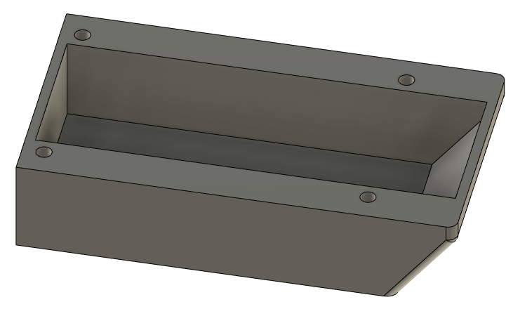
What about 3D printing something like this… super thick sides. Surely this is stronger than the ABS (I’m guessing) fin tracks and the surfboard its attaching to?
I’m thinking this with a aluminium top plate (or just bolt against the mast base) that can be used as a heatsink for the ESC.?? (excuse my crude CAD skills)
That approach will eventually work and presents an interesting opportunity to explore.
While intriguing, I veered off from that route due to considerations about excessive weight and risks involved.
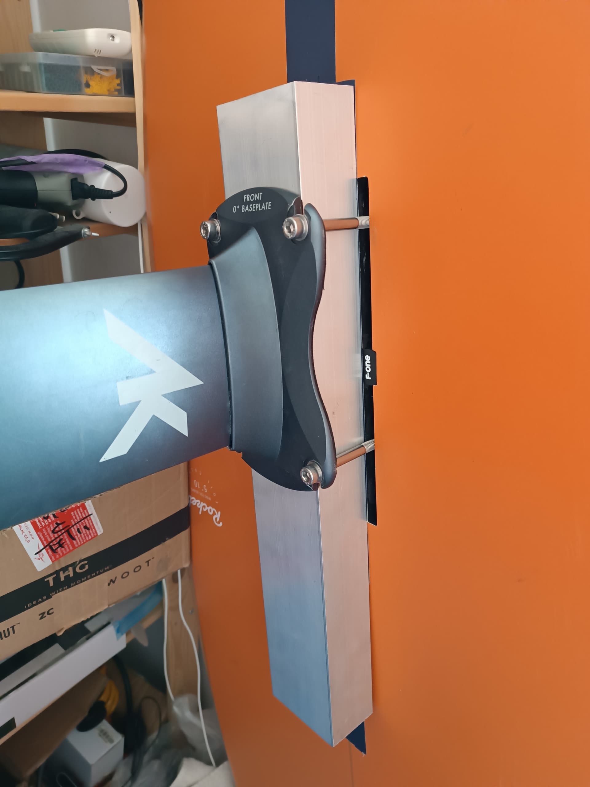
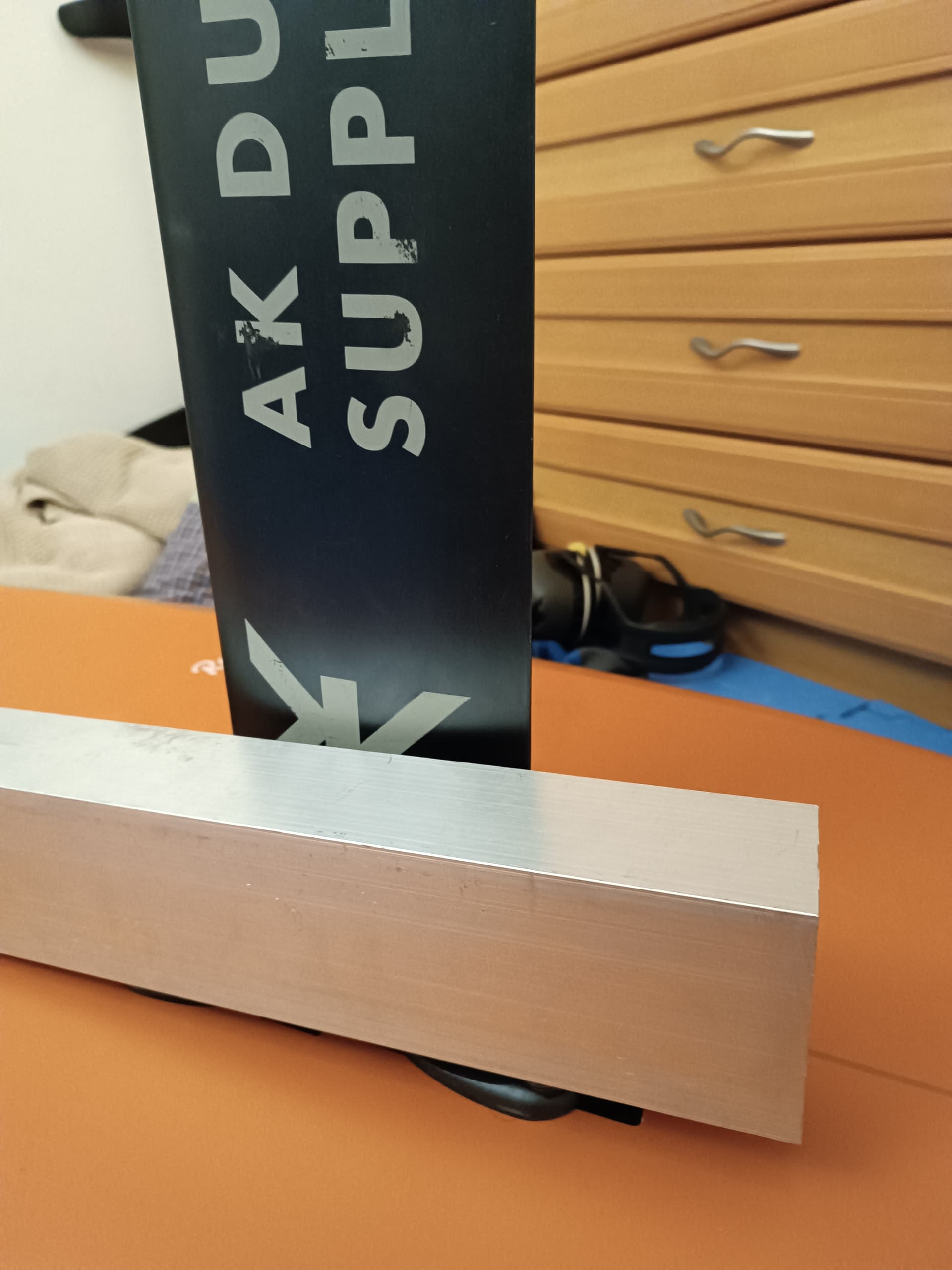
Instead, I will position the tube above the board first, then attempt mounting it next to the mast, attaching it directly to both the mast and its base.
Good idea @lishine - that takes the loading/strength out of the equation. I think having one row of battery cells either side of the mast might work (I was going to use 2x6s for my 12s setup) - be similar height to the FD Slim. My Axis base plate has additional threaded holes it could screw on to.
These strength-related aspects certainly complicate matters. I contemplated positioning components on two sides, but ultimately decided to try placing them on just one side since that approach is far simpler. I can start by getting it operational above the board first.
People often ride with a box mounted on one side of the board, positioning it towards the front. So having it mounted on a single side seems acceptable. It’s just a matter of compensating for the 2mm displacement caused by the added box by adjusting the feet placement accordingly.
So drag will be applied unevenly?
That is a good point that I didn’t think off.
But it matters only while speeding up.
The amount of drag is not more than say fdgen2.
yep. it’ll want to pull the board to one side while taxiing…but once on foil it wont be an issue.
I am contemplating having the cells upright, wrapping around the mast… 3d printing a larger foil shape to contain them. I think an additional benefit of this is that it can house everything in a foil shape rather than a box with rounded ends like FD#2 (which is not very hydrodynamic IMO).
The cross section of the batteries and components still needs to be accommodated - so the most efficient use of space plus in a hydrodynamic shape is surely going to be better. Of course the FD unit is very compact and would be hard to beat. Also I like it’s simplicity (just a rectangle) where as going around the mast is significantly more complex - but avoids having to deal with massive stress/load.
Will mockup something.