Appreciate if I could crowdsource confirmation of the BMS sample wire placement before I do this. I’m 94% confident it’s right but I want to be 99.65% confident. This diagram is based on @Jesserosco 12S2P layout. Thanks in Advance.

1 Like
I just made this pack with P45B Molicels and it works very well! Nickel strip needs to be doubled up in four places. Thanks @Jesserosco
Ludwig did a similar layout that only requires double nickel in 3 places but this layout is great because +ve and -ve terminate side by side.


4 Likes
Could you precise which ones ?


Original post about the hot spots from @ludwig_bre here Foil Drive Assist, DIY - #1435 by ludwig_bre
2 Likes
First build, I’m using 12S2P and using BMS for charge only. I plugged my battery into charge for the first time and it blew my XT60. Any advice about what I’ve done wrong here? The power supply wasn’t live when this happened, I plugged the XT90 in first then it blew when connecting the XT60. I thought the BMS would restrict any current to 20A max, which should be fine for the XT60. Should I have the power supply live when plugging in? Please ignore the bad insulation it was just for testing.


1 Like
When you say you “blew” the xt60, was it just a big contact spark or did you plug it in and suddenly it was heating up?
If it was just a spark it might just mean you need to do the xt60 first, then the xt90 (which appears to be anti-spark?)
I have a similar external Bms and I’ve had contact sparks if I do the wrong connection order. However I don’t think I’ve had it happen with a disconnected power supply. Is your power supply okay or was it salvaged from dubious provenance?
1 Like
The cheap chargers can spark when connecting and the burnt connector doesn’t have anti-spark, that’s the issue. More advanced chargers turn the circuit on gradually to avoid large inrush currents.
1 Like
Thanks. It was a spark not a gradual heating. I replaced the XT60 and tried again by plugging in the anti-spark XT90 last and it’s now charging without any apparent issues. My charger is a new (but very cheap) 2A from AliExpress.

STL Available? Now that I’ve built my lunchbox I’m keen to use it for other things too.
What stl file specifically are you looking for?
While testing Sequre 12200 in the air at home, I get jerk at certain rpm.
Is it solvable?
As people reported that this ESC working, I don’t understand how they use it while having that desync problem? Never had this problem with Xcross Blheli…
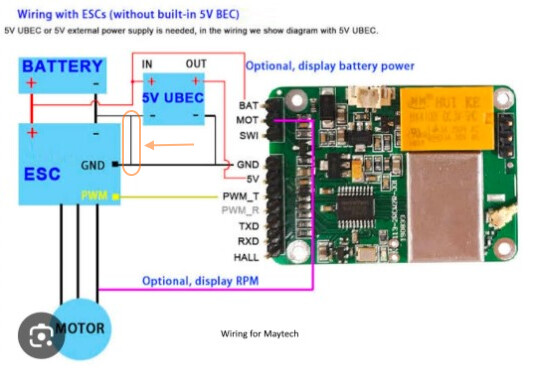
Can someone please help me understand why a BEC has a GND IN and GND Out? Then in the Maytech wiring diagram, these are connected anyway as I’ve highlighted in Orange here, why are they connected? I don’t think I added that extra connection into my build but it seems to be working ok. thx.
1 Like
Stops interference as pwm is twisted pair.
Run your pwm yellow black all way to rx as stand alone twisted pair.
Then 3 other wires
- battery voltage
- 5v from bec
Earth from bec (same pin as black of pwm)
I know its essentially same point when you look at it is more to reduce chance of interference or having earth floating up in voltage
Safe option just my 2c
1 Like
Both GND are connected, this is just to allow you to connect GND wires from the high voltage source as well as GND from the 5V load.
1 Like
Thanks @marcoz, so what I’m reading from that is follow this diagram but not include that extra bridge GND-GND connection that I circled in orange in the diagram. That is how I have done it, though more through being careless than by intention ![]()
![]()
How did you attach the box to the board pad?
Cell-Supply in Tauranga should be able to help. I am about to start my first battery and will try them out. Can feedback if needed…or could buy in bulk together for better price
Has anyone got a printable design for these mounts to hold the box to the board?
I’ve already got the dual lock and the bunnings strap so would love to avoid paying $100 (NZD) for two bits of plastic.