I’ve been dreaming of building one for years, but the fiberglass always put me off. I’ve built like 8 VESC OneWheels and am active in the VESC discord server. This is the first build guide that I thought to myself “yeah I can probably do this”.
Yes. It’s one of the easiest way to get going. We have build several boards, and the fiber glassing was also for us the part we did not like.
Anyway. We have done a small update to our board.
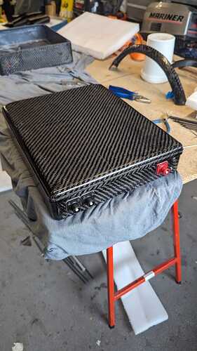
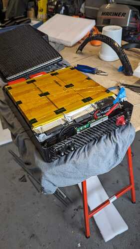
It’s now got a 15S1P just over 3kWh battery in it ![]()
Wow beauty!=========
Very nice!
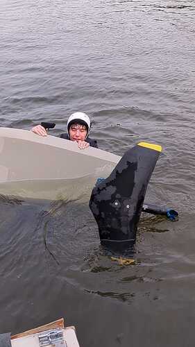
I’m still waiting to hear how that Tritonfoil wing works out. Have you ridden it yet @Kian?
Yes, I did test it one time till now.
It’s still too cold here to do a good test, but the time I did test it, it felt really smooth and very direct! The speed range is wide!
Absolutely no front foot pressure was needed, and I’ve never been on the foil this quick; it was very direct.
As better weather is on its way, I hope to do a full review really soon!
15S. 1P??
Tell us more😀
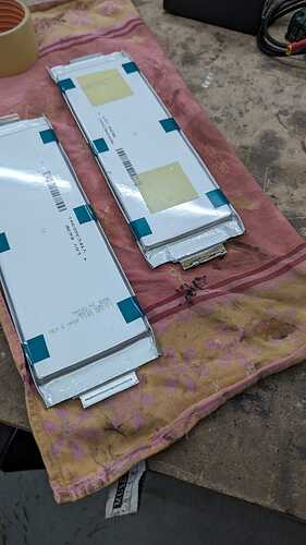
15 times a LG Chem E63B in series = 15S and all in 1 parallel row. (1P)
Ahh yes I recall you were designing a pack using pouches. ![]()
Quite amazing that there is 60Ah in a pouch!!
Did you decide you require a higher than average V level or was that more the size of the pouches made that a logical number - 15S
Happy to hear that the initial water test went well! Sort of Brrrrr where I am to😀
As I already have a 12S9P, and really wanted to try a 15S, and make the local Fliteboard boys jealous with it, I (actually my dad) decided to build the 15S.
We have 16 pouches, but no way it would have fitted.
Hi @Kian, I am curious what technique you used to fasten the battery tabs together with those pouch cells. I am considering making a pack like this at some point, I’ve seen a couple nice EV modules for sale with tempting high power high output cells like this.
In your photo above it looks like a 3D printed cover is in place to protect the connections, but what is happening underneath? Usually solder is not an option for these pouch cell tabs. I have seen some use rivets, others have made clamps that screw together.
Also, seems you put a small BMS on there, probably charge only. Since it’s a 1P pack it can’t do any balancing, so is it merely controlling your full charge voltage?
Hi Silas,
My dad got a lot of good tips from Kwin (from eFoil Holland).
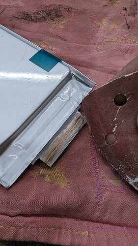
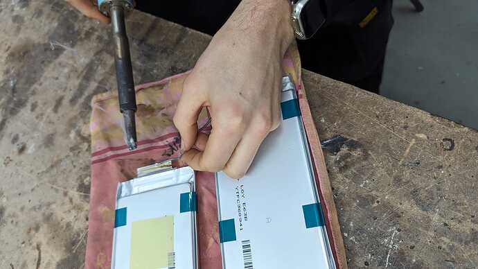
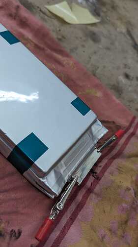
Basically, you do solder the tabs together! One side of the aluminum tab is copper-plated. (see picture 1) Use some fine sandpaper to roughen the copper side (picture 2), pre-tin both COPPER sides you are going to solder (picture 3), use some crocodile clips (picture 4) to keep the two tabs (copper side on copper side) nicely together, and use a strong soldering iron (we used a 150-watt one) to heat the tabs until the solder flows nicely together.
We used double-sided tape on the pouch itself to keep (in our case) the stack of 5 pouches nicely in line.
It sounds more complicated than it actually is.
The pack is a 15S1P, and the intention was to use the BMS also for discharging as it was supposed to be able to handle 120 amps.
Unfortunately it cuts out at 70 amps, and so not usable for discharging.
Now we only use it during charging and balancing all the cells.
Ah, interesting. Thanks for that, you even had photos ready to go! This approach looks good but probably only works on certain cells that include that copper strip, not sure how common it is.
I have seen people drill two small holes in the tabs, and use small bolts/nuts to keep them together.
Yes it does balancing between each cell too.
Yes, thanks, realized after I posted that balancing was still needed and the parallel count is irrelevant.
I’m curious about how you are finding the
wing.
I am working on a video with all the info, so stay tuned for more details.
~Spoiler: It’s a great wing with a wide speed range. It’s not really made for general cruising (it’s sensitive in pitch), but for having XXL fun, it’s a great wing. I’m even starting to use it for jumping. (still need to work on the landings ![]() )
)
Awesome looking build! Im wanting to do something similar, did you remove the original aluminum heat sink and mount the circuit board directly to your aluminum plate or did you machine the fins off the original heat sink and mount that to your plate?
I removed the casing from the 75200, and fixed the PCB bottom (with cooling pasta) directly to the aluminium baseplate.
So basically it is mounted exactly the same as it would be inside the original casing.
Thanks for that. I was hoping that was the case. Ive also got a 75200 vesc ready to go.
