FS65161 bluetooth connection diagram

hello friends
I bought flysk 65161 engine kit
The Group W7 Aquatics Kit includes:

1* FSESC75200 75V with Water Cooling Enclosure
1 * FS65161 12MM Shaft
1 * VX3 Waterproof Remote control
1 * Propeller
1 * XT90 Battery Transfer Cable

I couldn’t connect
I searched all the form sites, but still couldn’t figure it out.
please help me…


Here is wiring diagram
https://flipsky.net/collections/electronic-products/products/flipsky-fsesc75200-75v-high-current-200a-esc-base-on-vesc-with-aluminum-heatsink-for-e-foil-fighting-robot-surfboard-agv-robot-arm

According to the diagram here, it will be plugged into the bluetooth 1 (UART2) channel. am I wrong

I’m not sure I understand you.
If you want to connect receiver, you should use the port marked with number 1 that is called UART 2 on this diagram.

You don’t have bluetooth in your setup.

Uploading: WhatsApp Image 2021-08-19 at 13.03.18.jpeg…
sorry my english is very bad
I will make the connection like this

is it true?

I’m sorry,

I now see that UART 2 has only 3.3V, but on the receiver schematic it needs 5V.
I’m not sure will it work.

Check each wire that it goes according to the wiring diagram before connecting VESC on the battery

does the blue wire need to be connected directly to the battery ???

Got the same problem.
This is my Solution:

On the desk it‘s working fine.
Hopefully also in the water. :wink:

There are many wires in the place I marked with blue, where are those wires connected?

To be honest… no idea. Maybe some of the experienced useres could give an answer to this.
Thats also my first FS ESC/VESC.
But as i said…its working fine. So…no doubt about the other cables :wink:

could you please send me the esc and the photo of the receiver

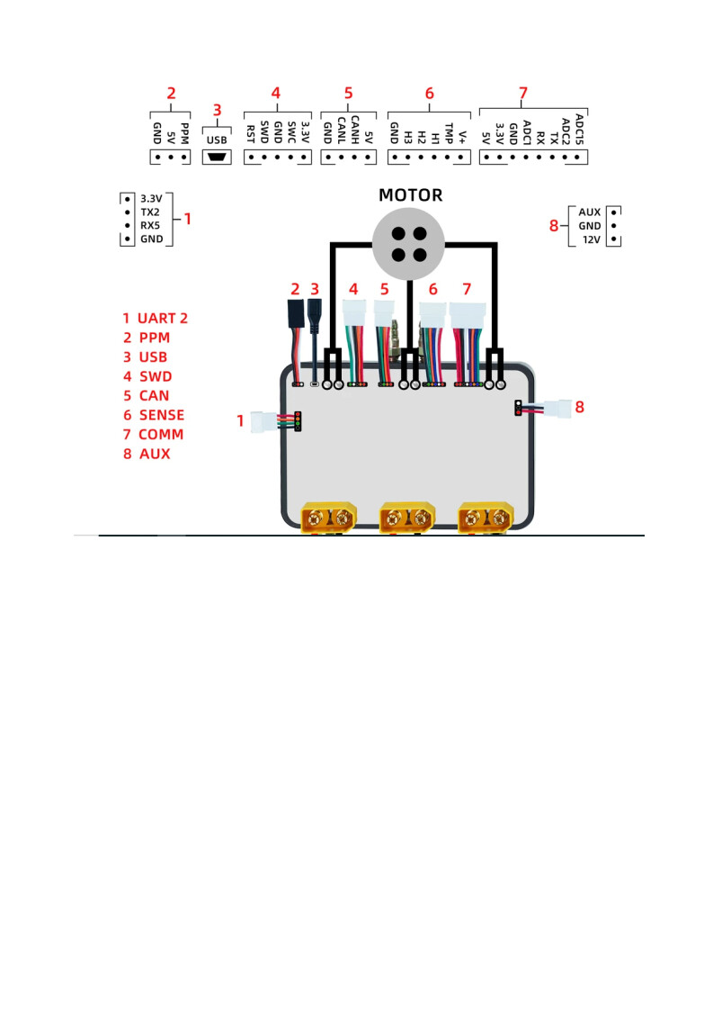
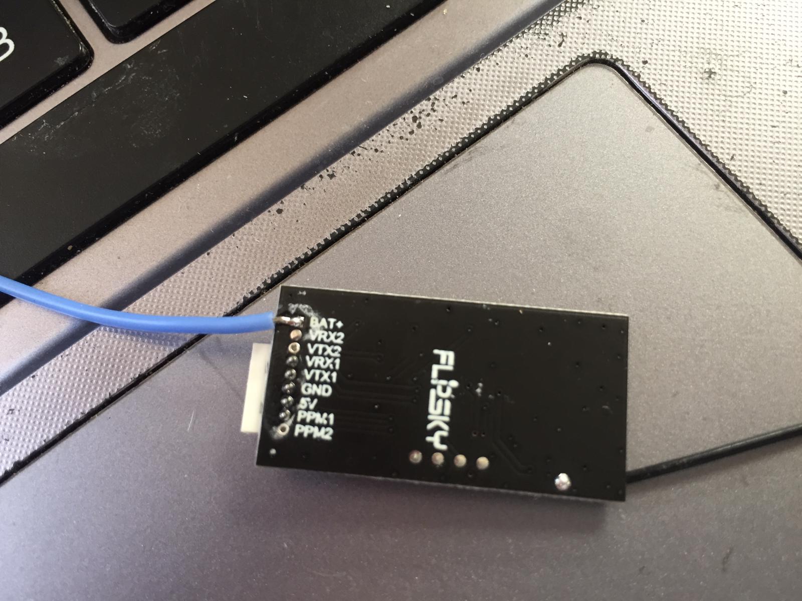
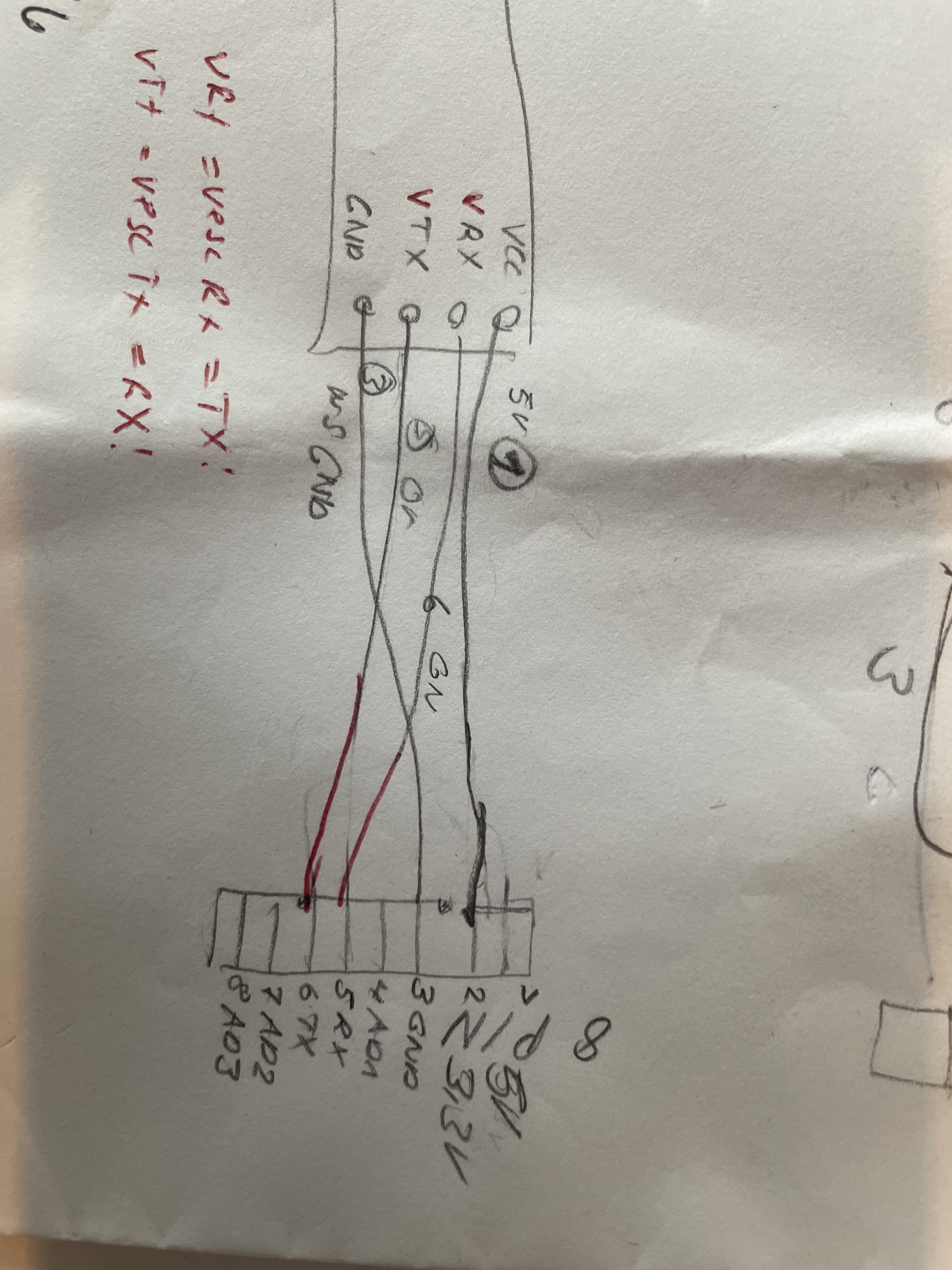
This is the standard uart with adc inputs you don‘t need. Not sure if it works with uart2 out of the box, it does work with uart1 for me. It works with 3.3V. The Flipsky BT only need 4 wires, gnd, vcc (3.3 or 5V), rx and tx.

Uploading: WhatsApp Image 2021-08-19 at 14.18.40.jpeg…

i connect the receiver to the UART2 cable on the esc

black cable:gnd,
red tie: vcc ,
green cable :RX5,
orange cable :TX2

Seems it should work.
It would be really absurd if the only connector on FSESC that fits in FS receiver isn’t working.

I found flipsky very unsuccessful in this regard.
they can use more simple and convenient sockets
Thank you Mislav


You should solder the connector as @sat_be showed in its diagram. It is the widest one on the vesc, see image attacged.

@sat_be @Mislav @Olli @TheEngineer
Is the diagram I drew correct?

Looks OK, if it doesn‘t work, connect it to connector 7 (uart 1 on 8 pin connector) instead of 1 ( uart2 on 4 pin connector).

I haven’t had a chance to try.
I will try as soon as possible and I will let you know

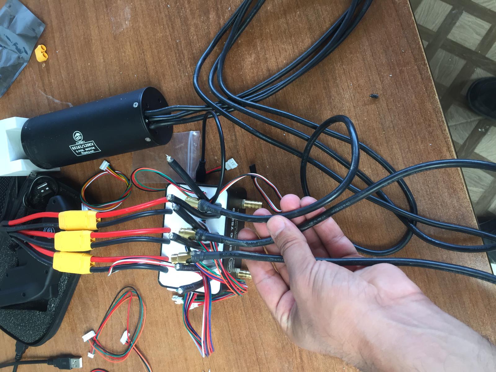
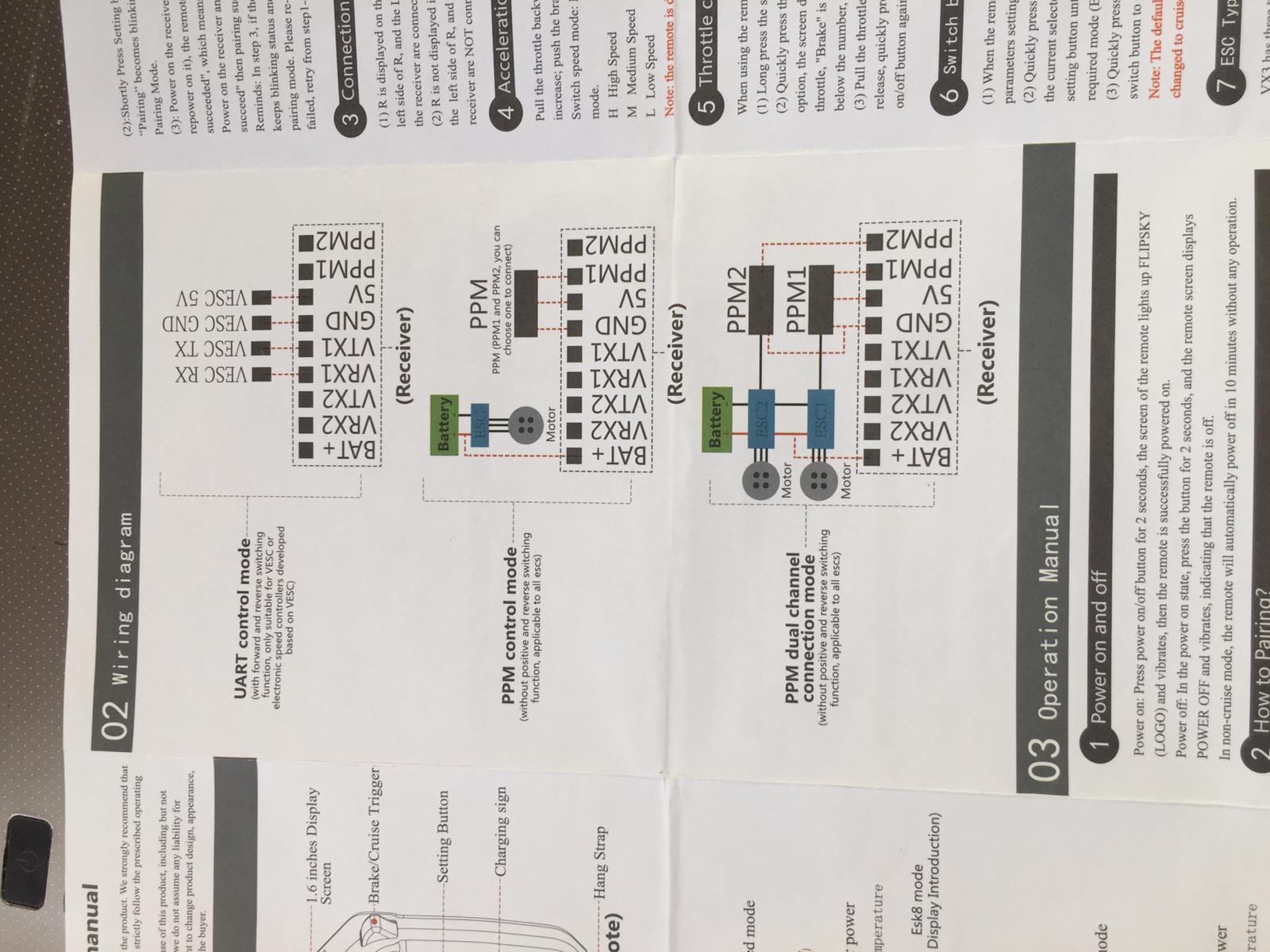
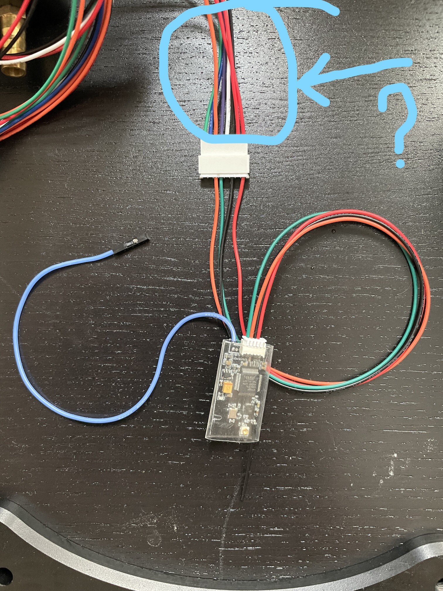
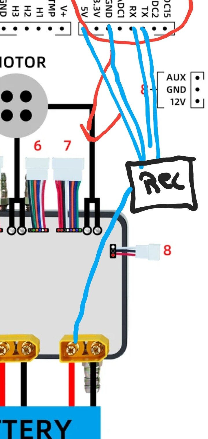
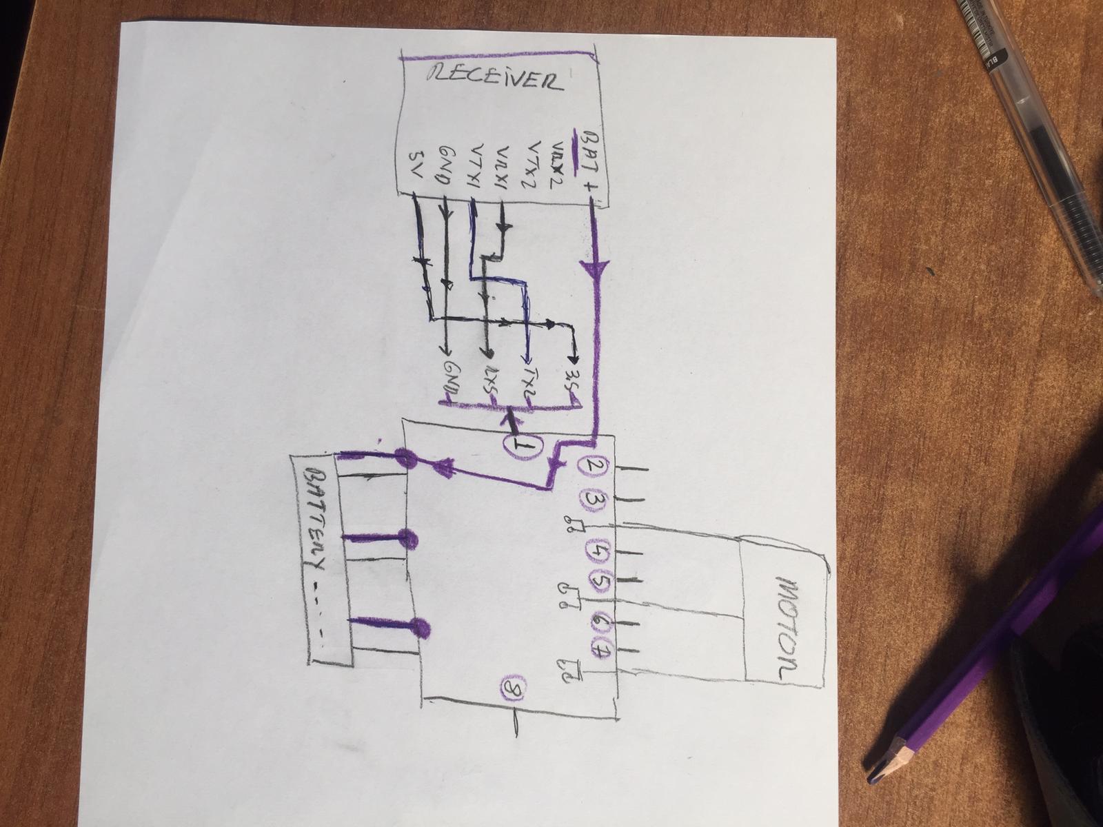
Not sure I understand the recommendations connecting the BT receiver to the FSESC UART2 port (1) connector with 4 wires. The easiest way to power and send control to the FSESC is via its’ PPM port (2) connector, 3 wires are all I needed. Port/cable 2 (in the simple Flipsky diagram) is Pulse Position Modulation (PPM), there are 2 outputs PPM1 and PPM2 on the BT board. If you are unfamiliar with PPM, it’s a 3 wire interface that drives both manual servos & ESC in boats, planes and heli’s.

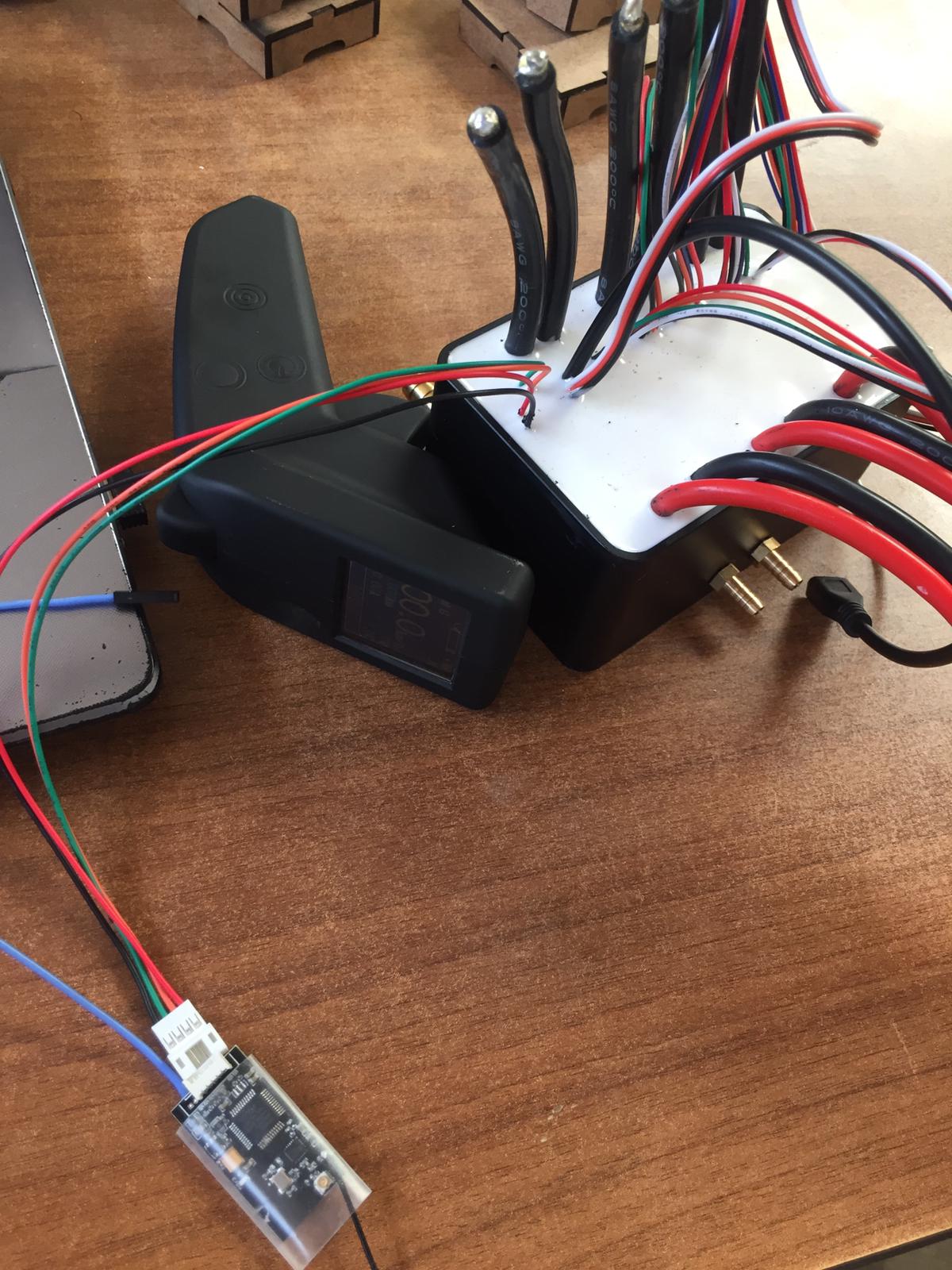
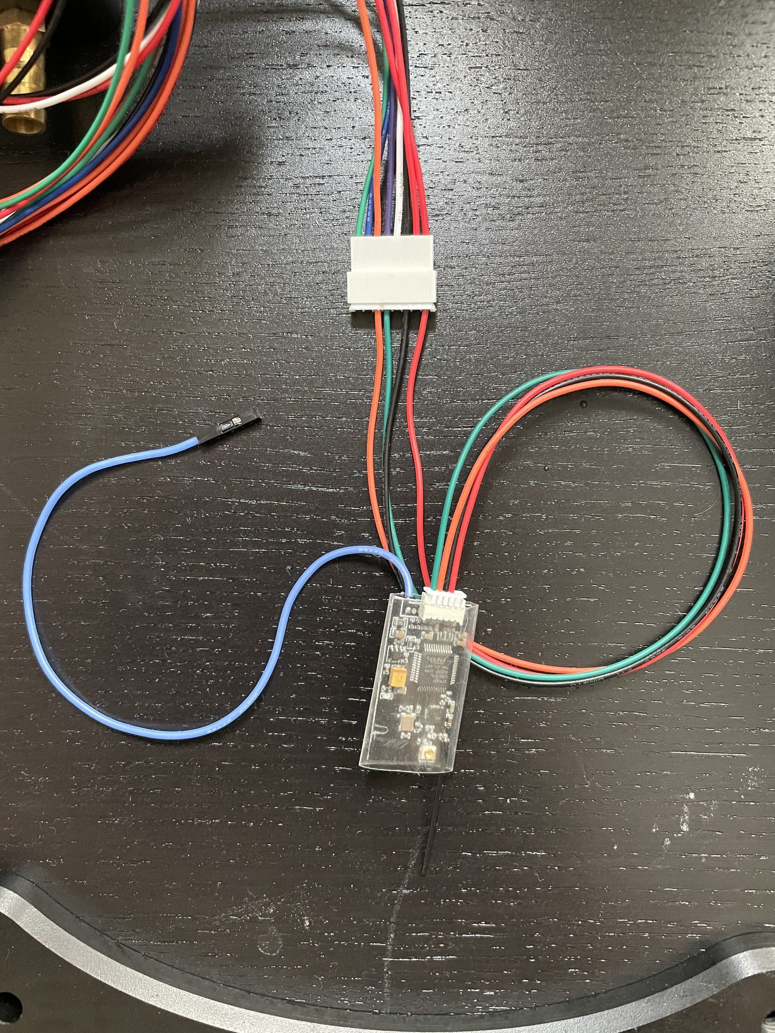
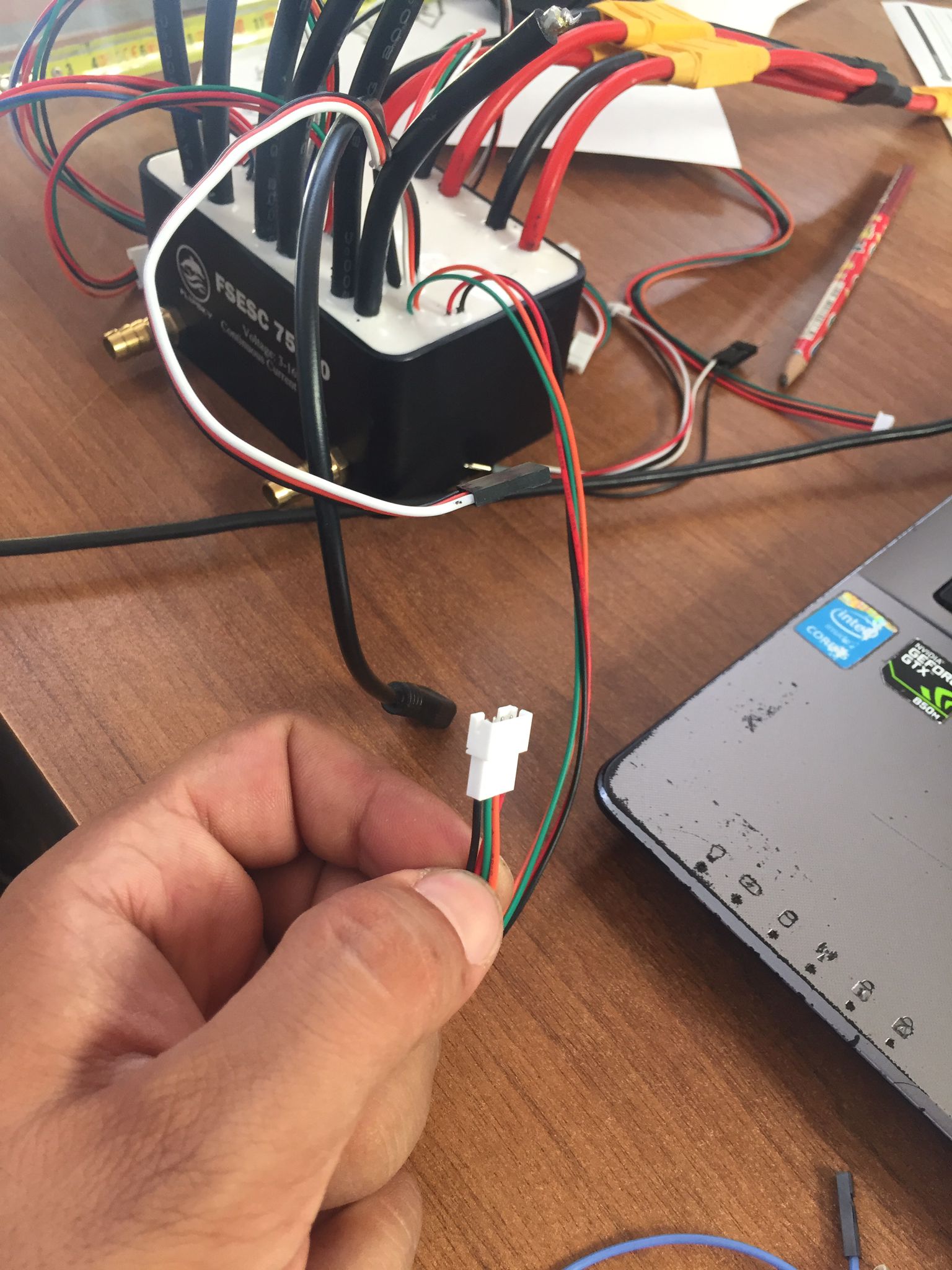
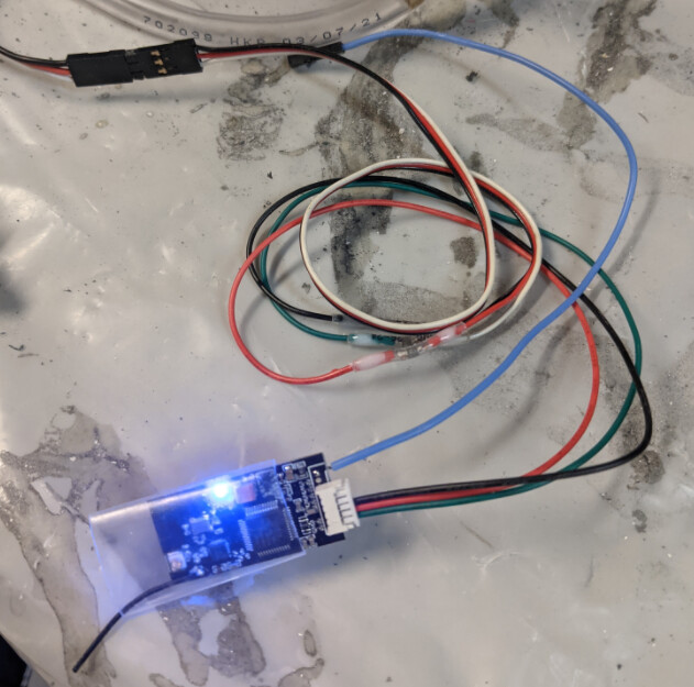
I connected PPM port (2) on the FSESC to PPM1 output from the BT receiver which has the following 3 cables:

  • black - ground
  • red - 5V (5.12V when I tested my rig)
  • white - pulse position control signal

Also, FSESC PPM port (2) connector gave me plenty of power to drive the BT receiver board. I setup a cable as shown in the paper instructions from flipsky. GND, 5V, PPM1. I then used FSESC AUX port (8) to drive my 12V water pump.

Am I misunderstanding the advice to use UART2?

1 Like