DIY E-Foil Build – Custom Board + Budget Performance Setup
I finally decided it was time to try e-foiling, so naturally I turned it into a full DIY project. My goal was to build something reasonably affordable but still performant. As with most DIY projects… things evolved along the way ![]()
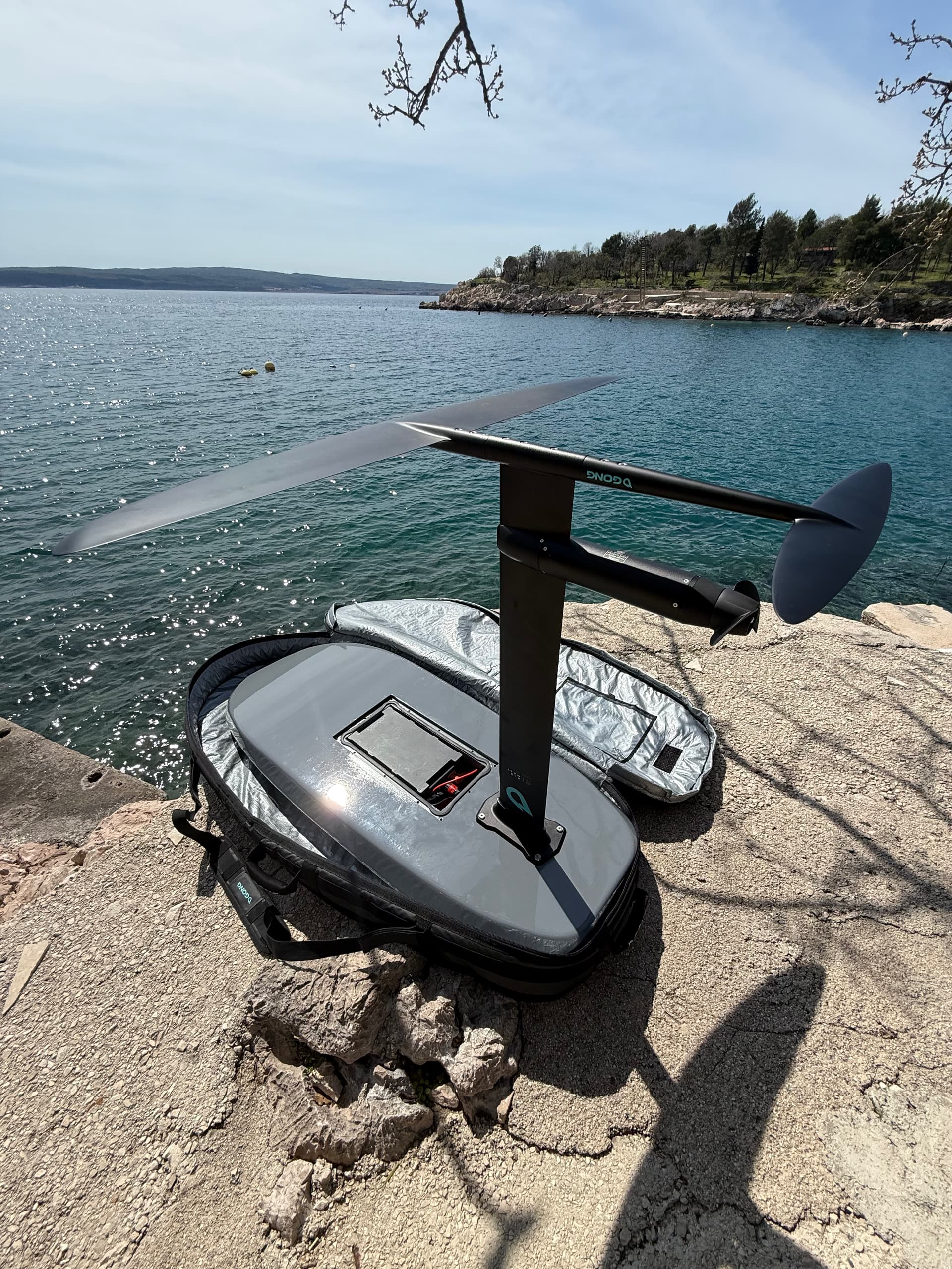
For the foil itself, after recommendations from a couple of good friends, I decided to go with Gong.
Build Overview
This is what the setup currently consists of:
- Custom board
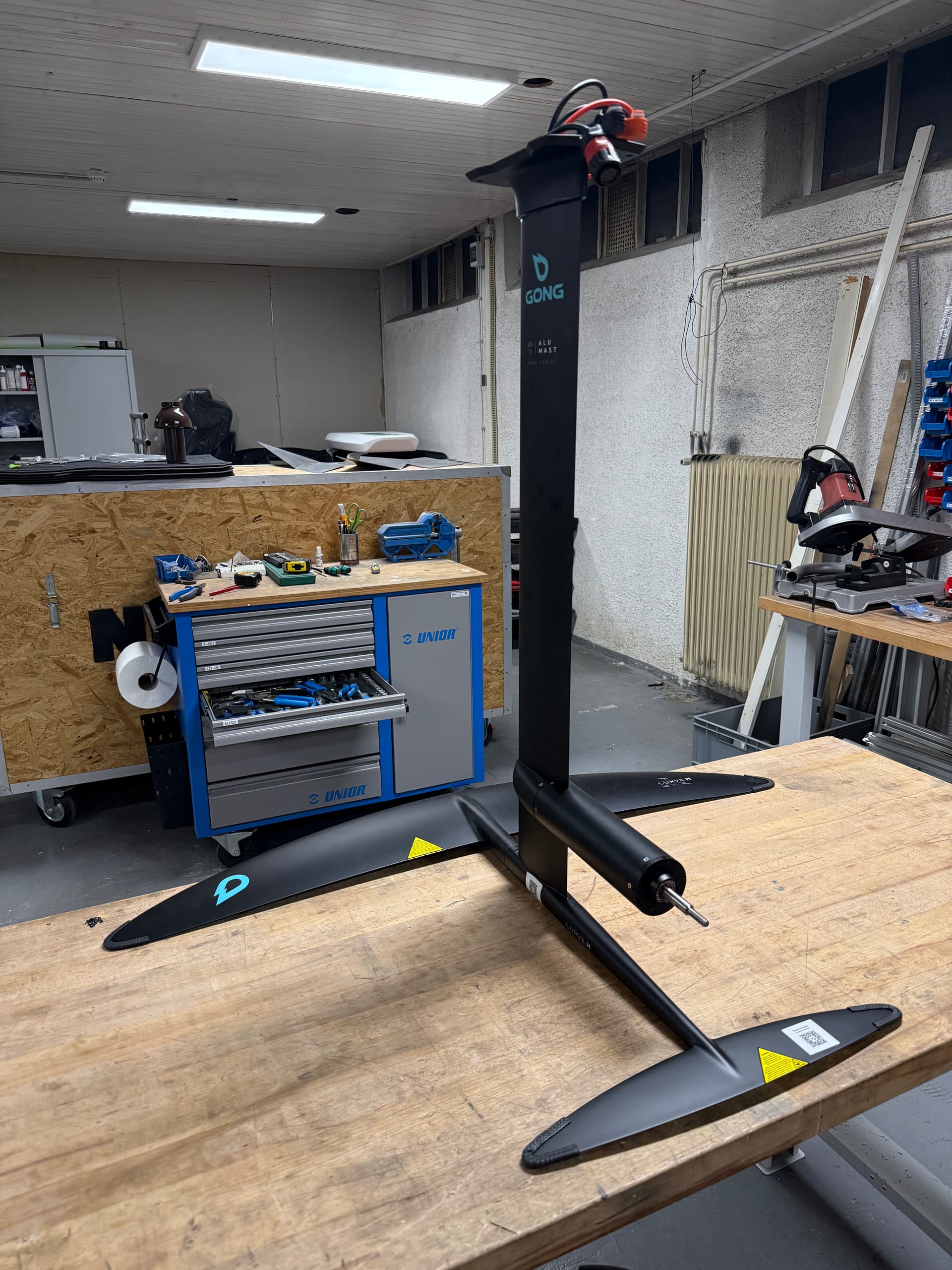
- Gong Curve H v3 FG XXL front wing
- Gong Curve v3 FG XL stabilizer
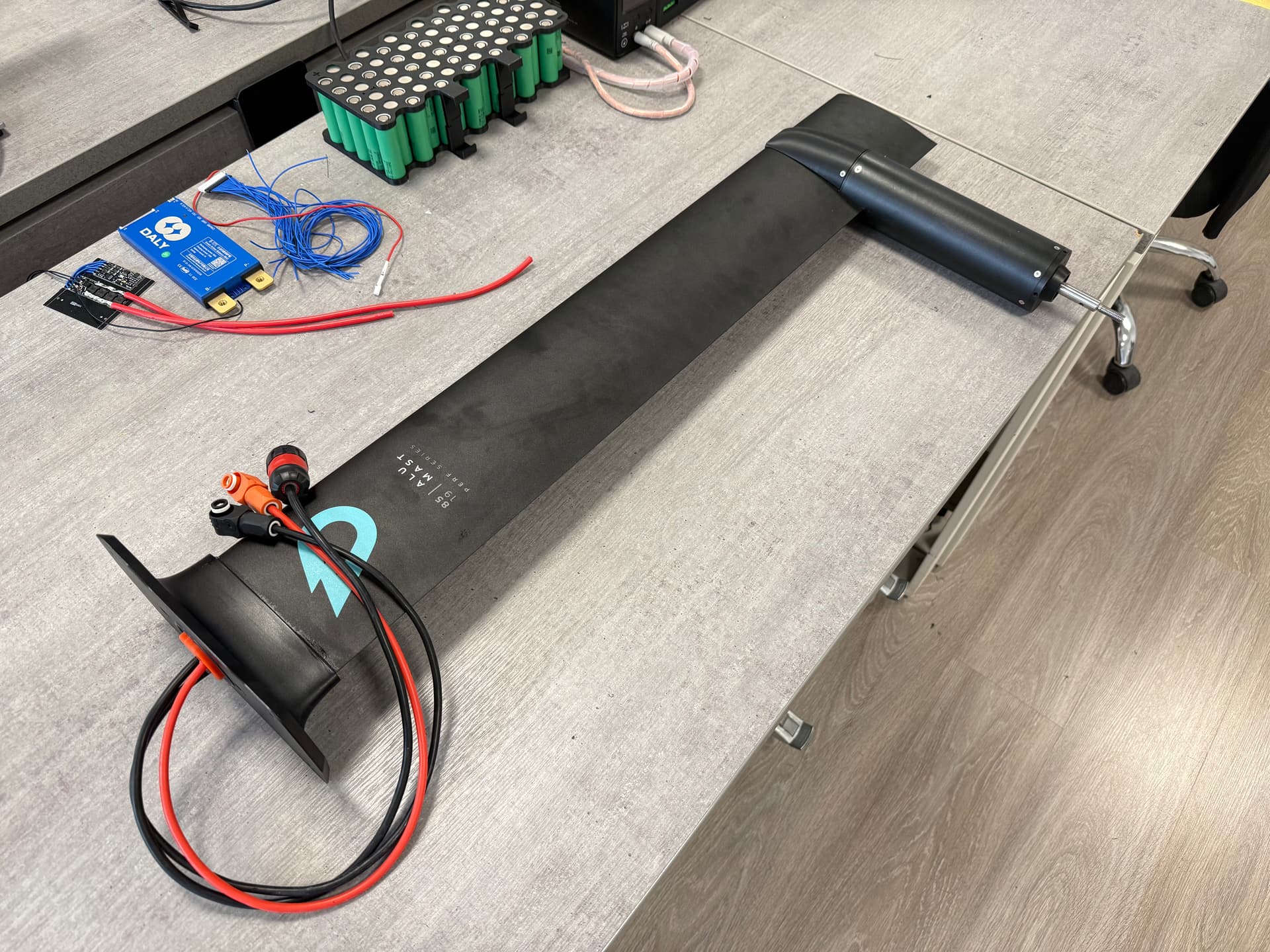
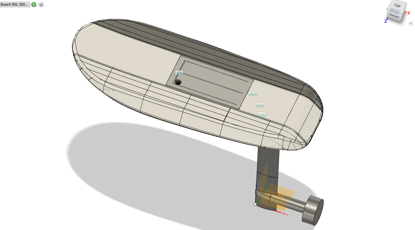
- **Gong Alu Mast 19mm 85CM
- Flipsky 65220 motor (watch for AliExpress discounts
 )
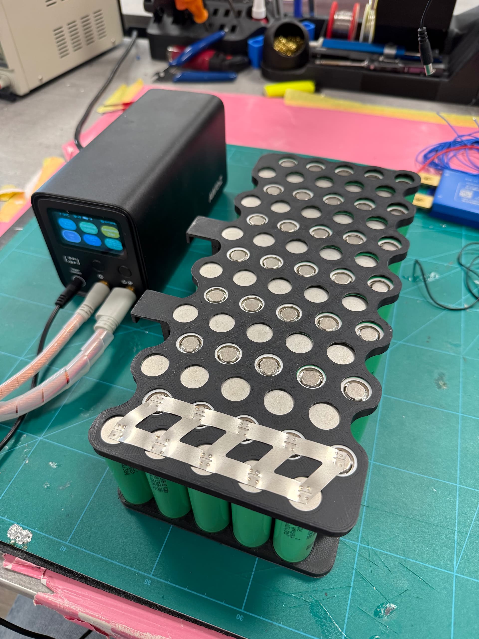
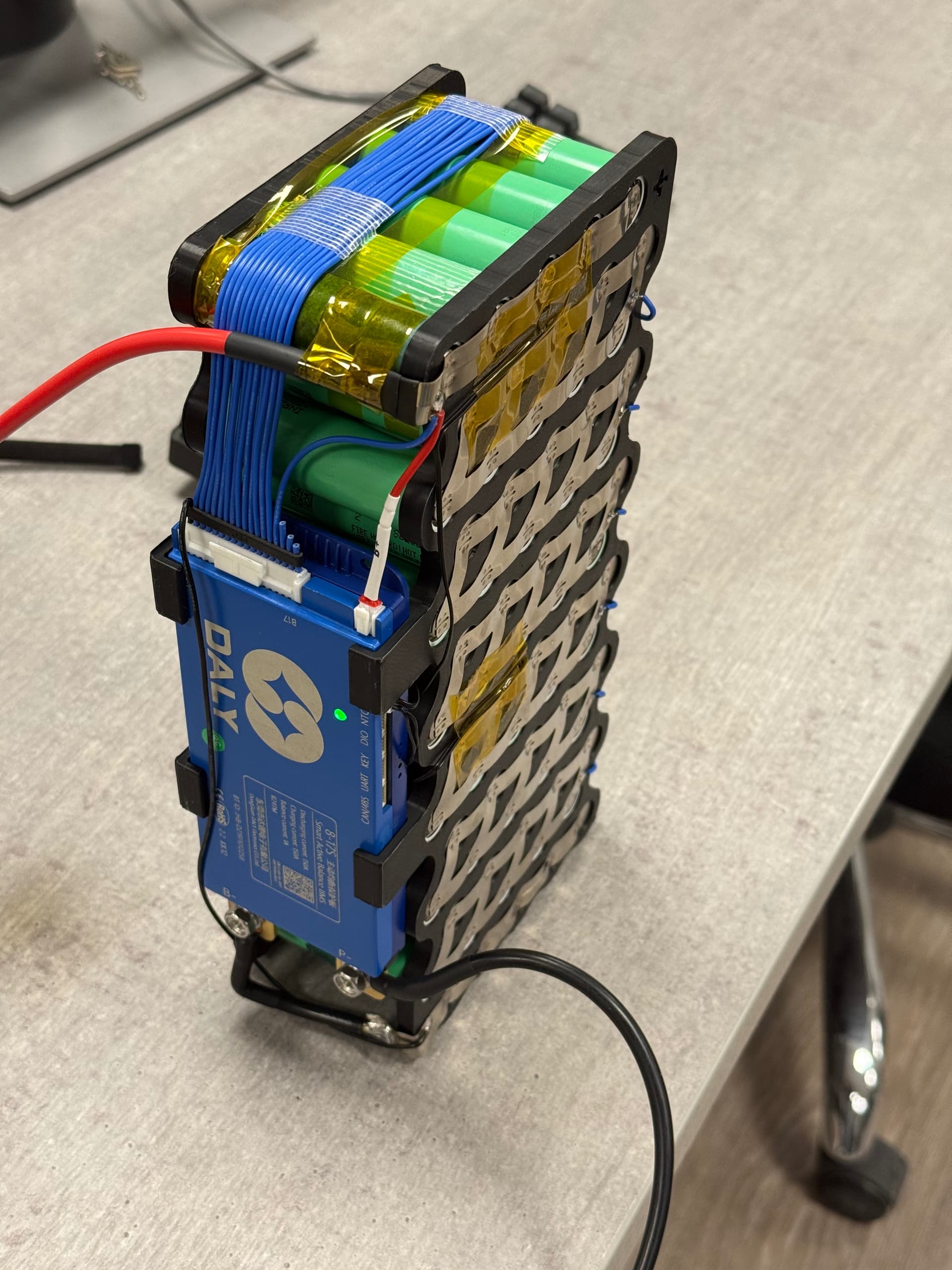
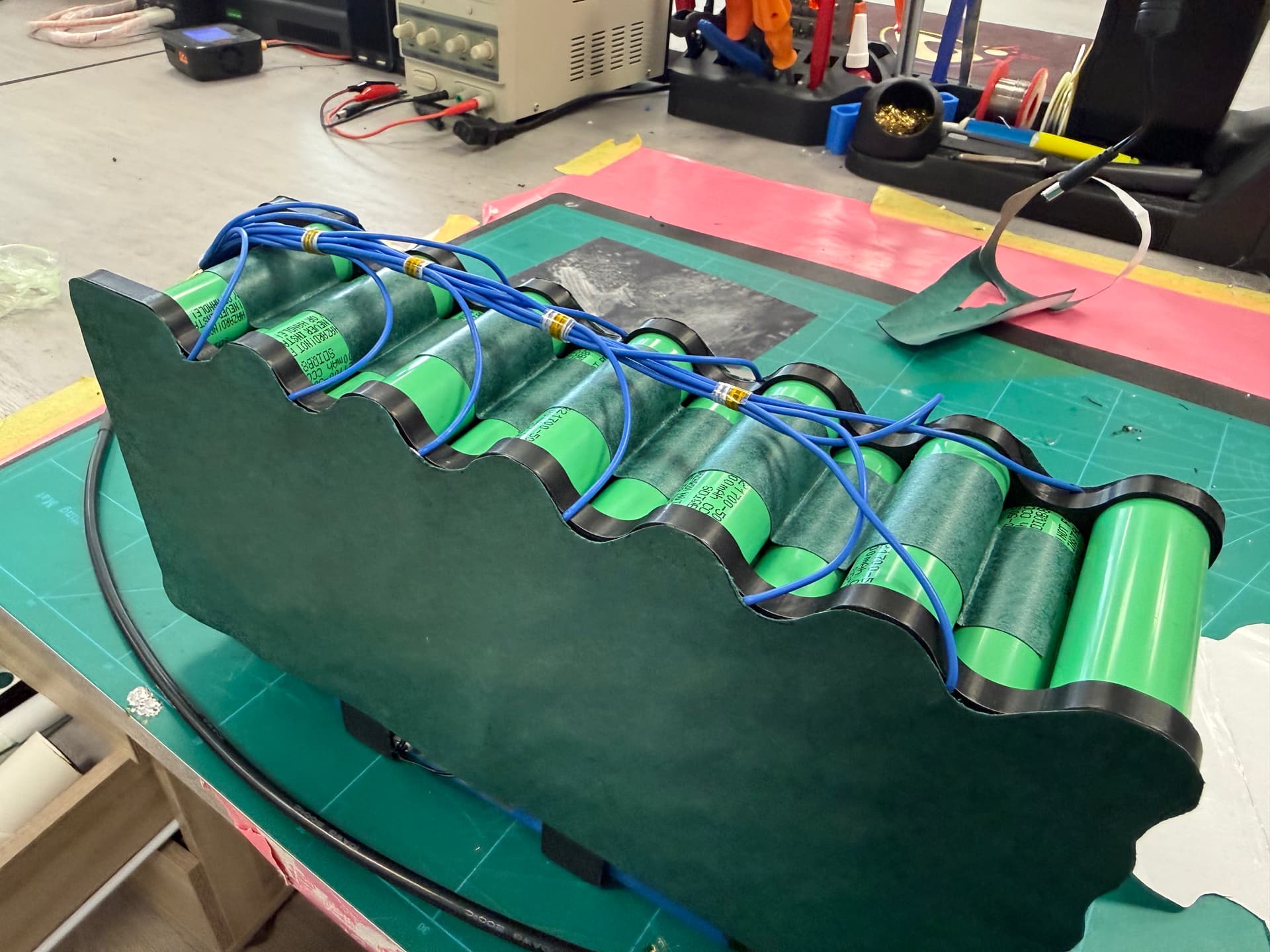
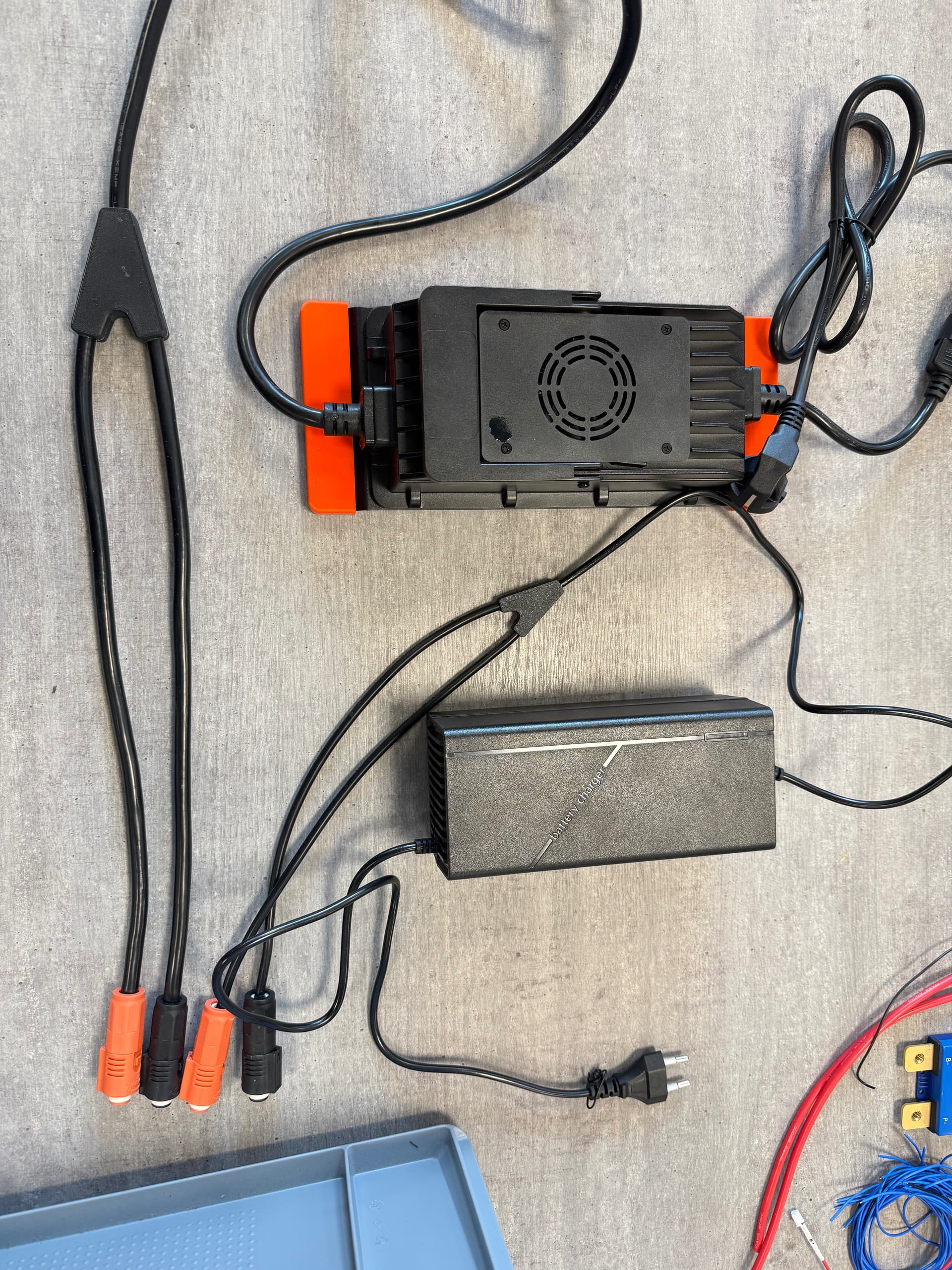
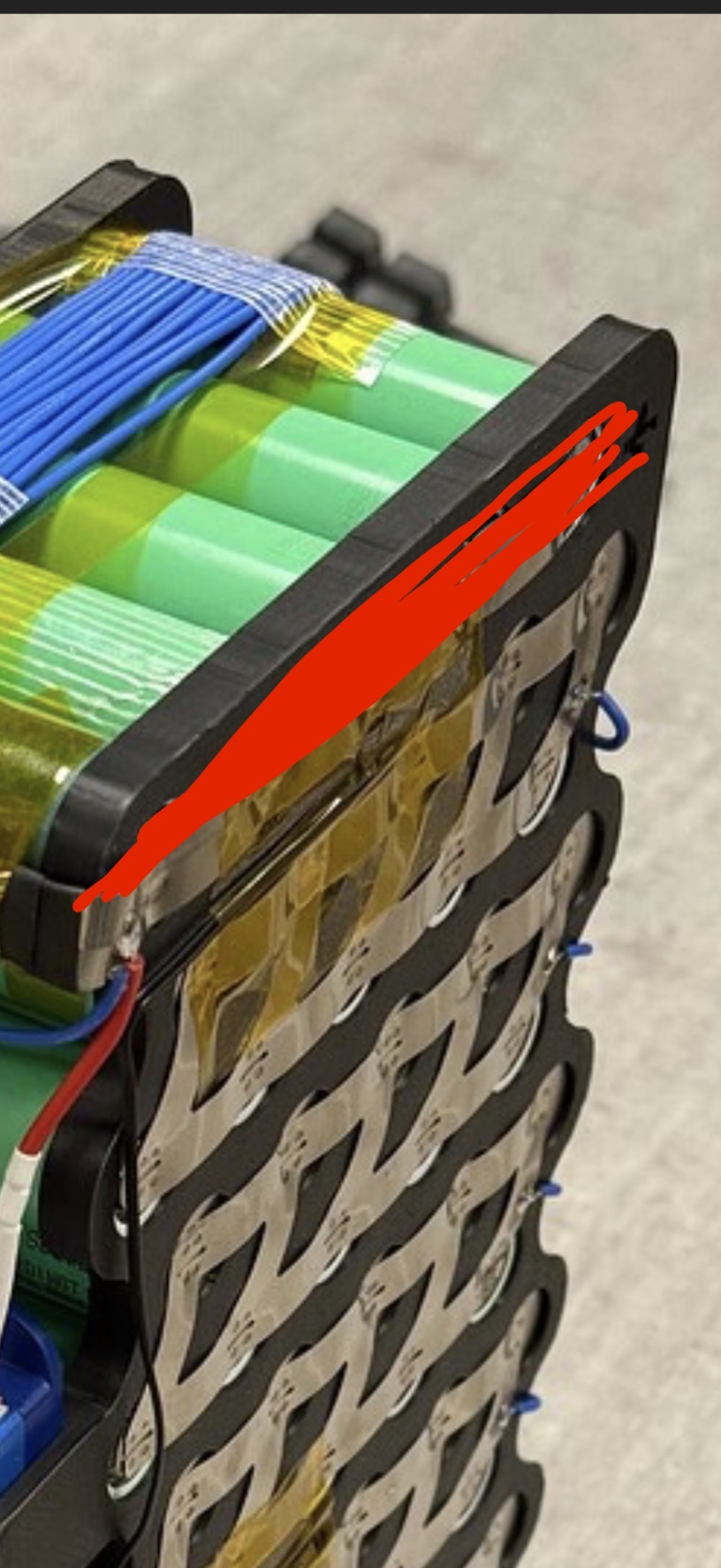
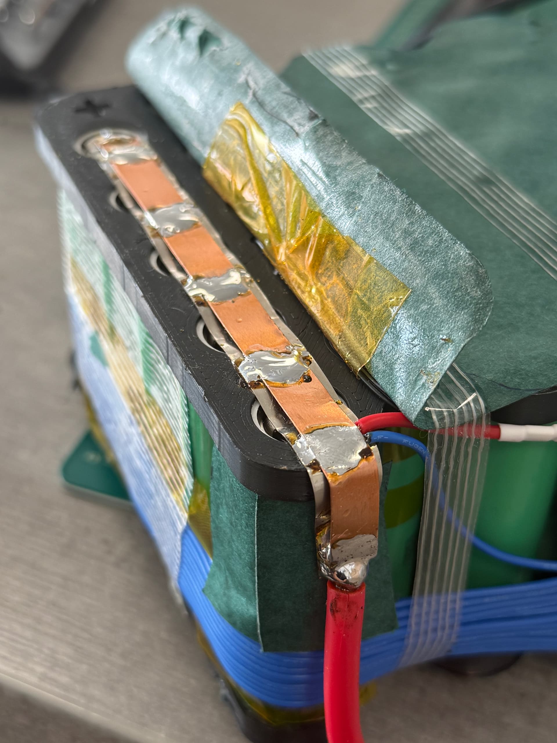
) - Samsung 50S battery – custom 14s5p pack
- Flipsky VX5 TX/RX remote (also worth watching for discounts)
- Daly Blue BMS with reed key switch (acts as a kill switch if needed)
The target budget was under €1800, but reality hit a bit:
- Upgraded remote
- Had to CNC the adapters twice
So right now the build is just above €2000.
Worth mentioning:
I already had most of the tools and some spare glass fiber and epoxy, which definitely helped keep the cost down.
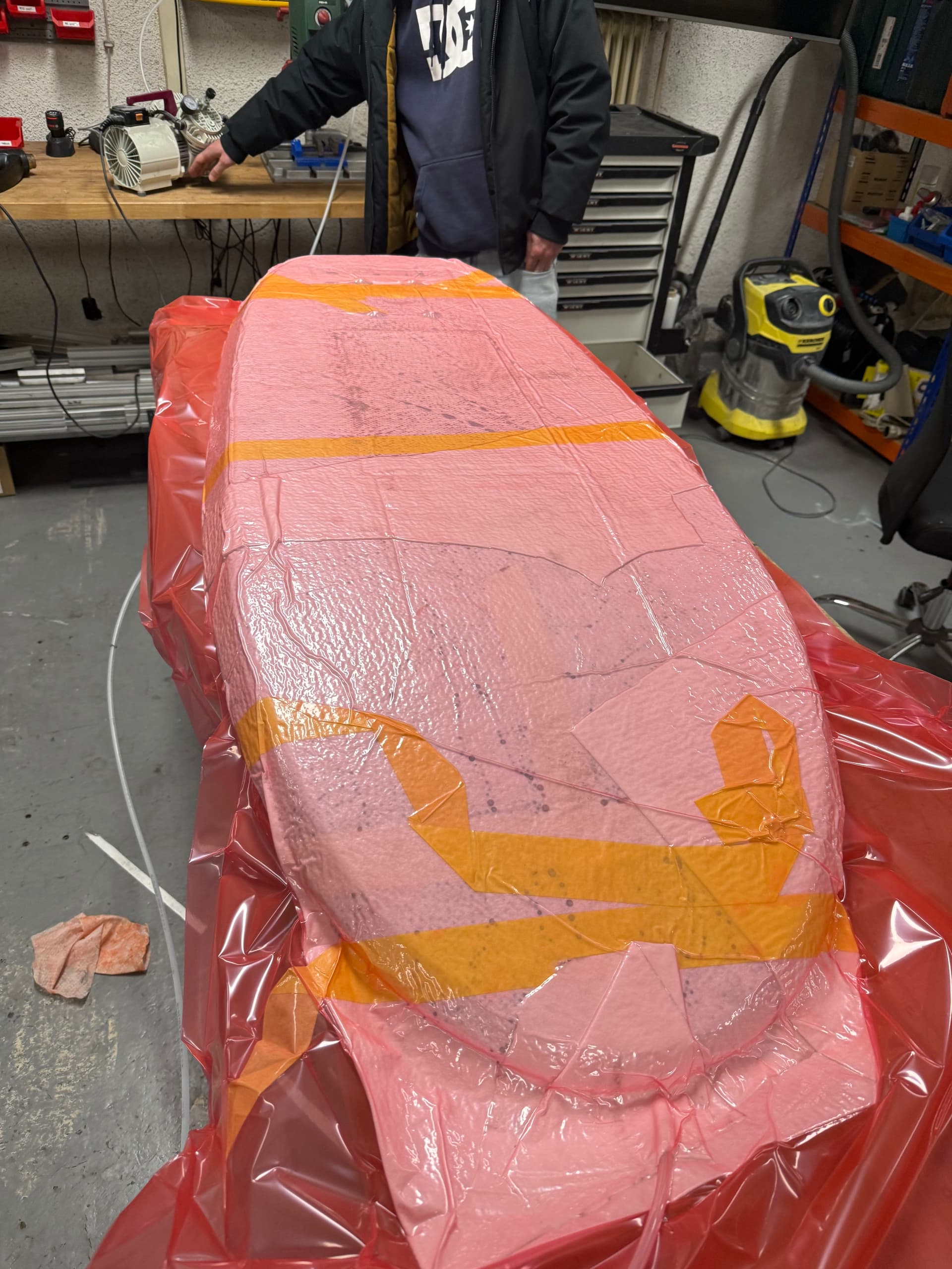
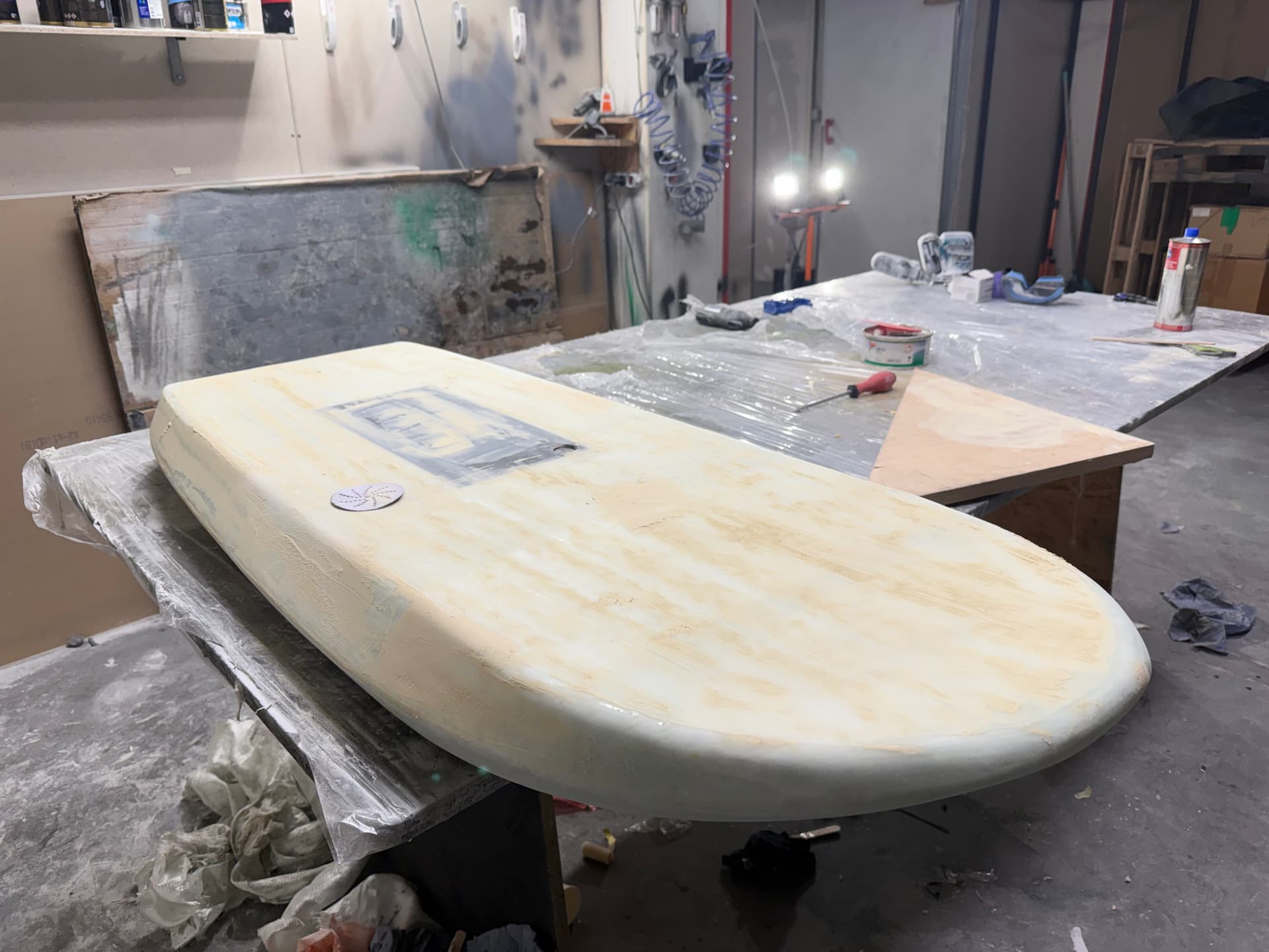
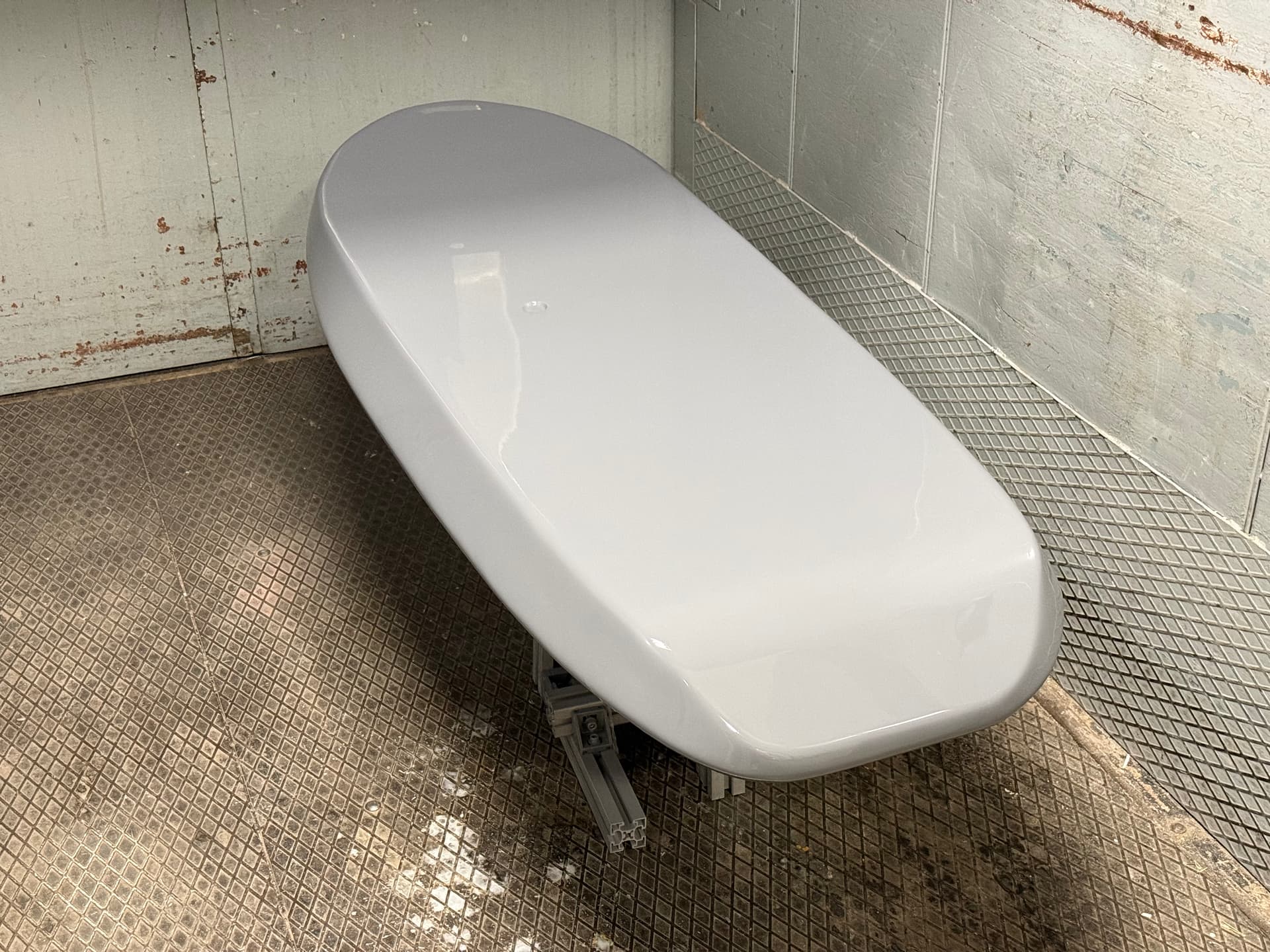
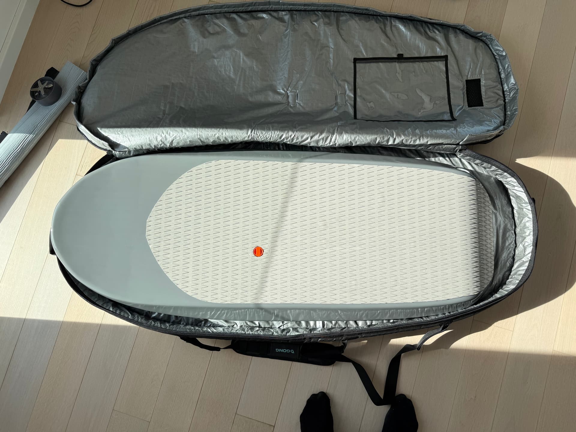
The Board
Initially, my plan was to build the board from a fully 3D printed shell.
The idea:
- Print the shell in 18 separate sections
- Glue them together
- Fill the inside with PU foam
I ran quite a few tests using different materials:
- PLA
- LW PLA
- ASA
But every option had some drawback:
- Warping
- Poor layer adhesion
- Low heat deflection
- Too heavy
- Too expensive
- Or simply too much work for the result
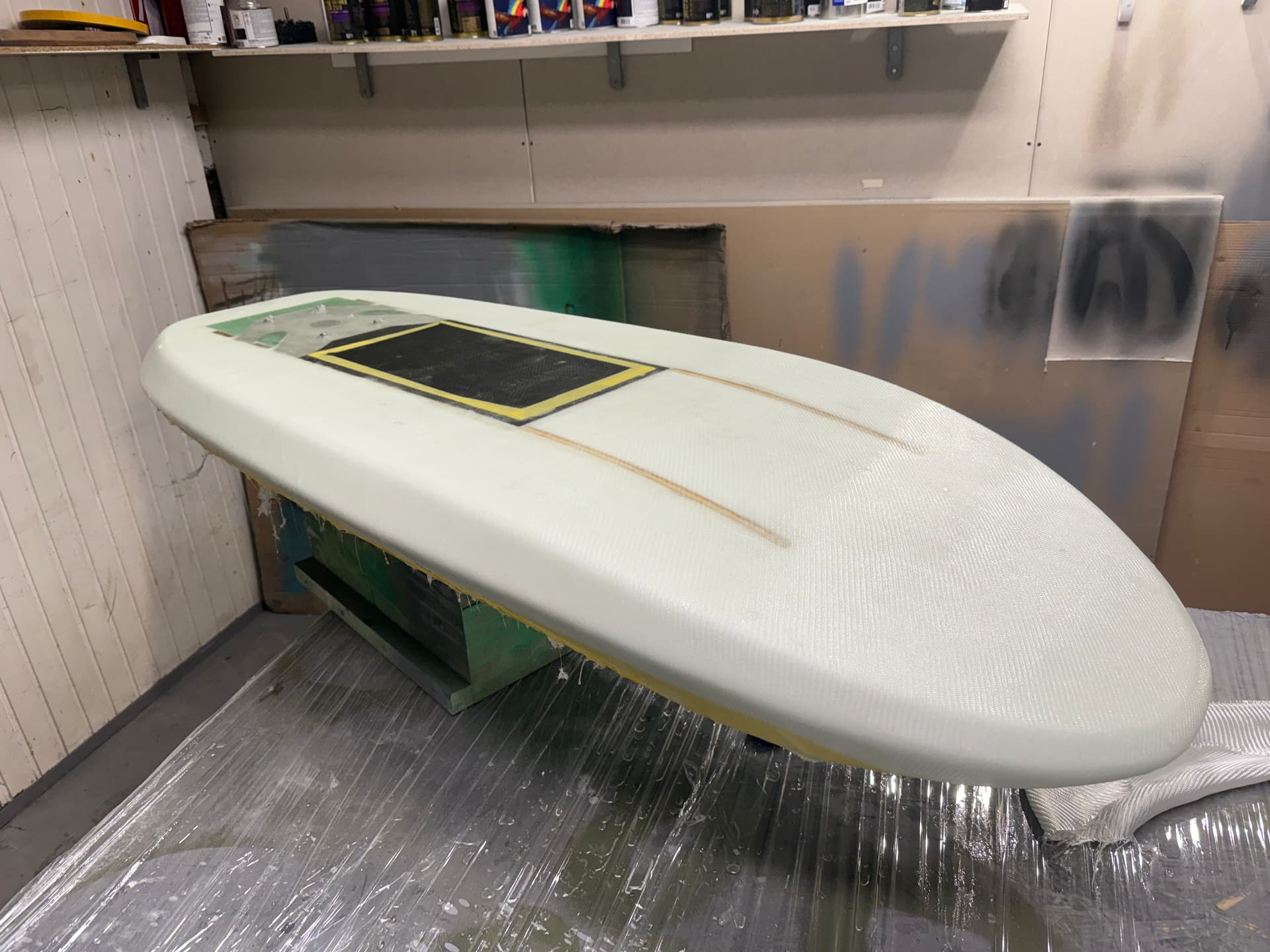
After fighting with this for a while, a friend stepped in and CNC-cut the board core.
Honestly… total lifesaver.
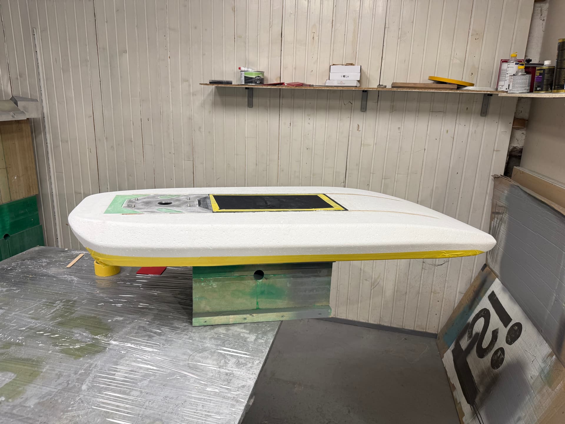
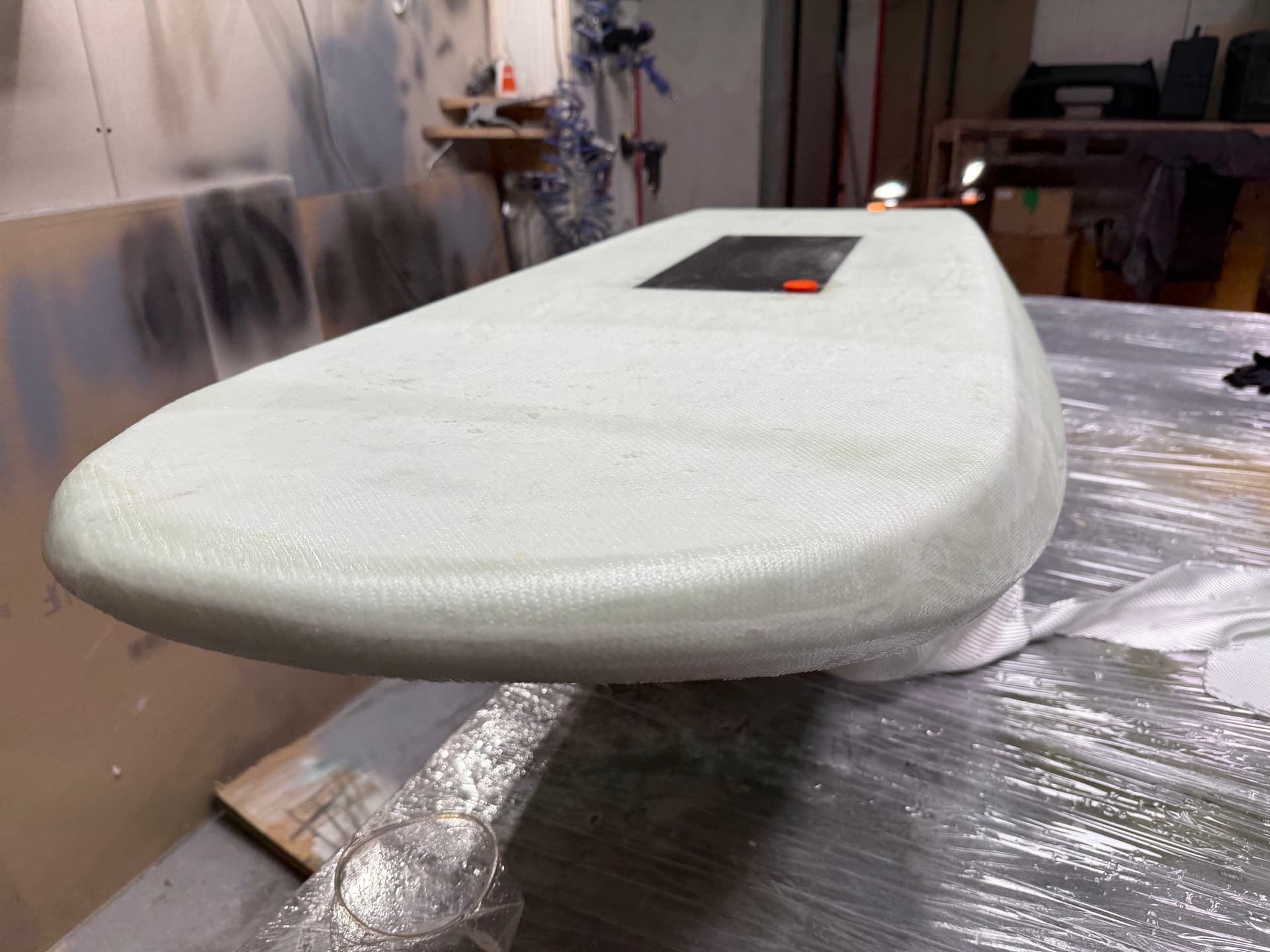
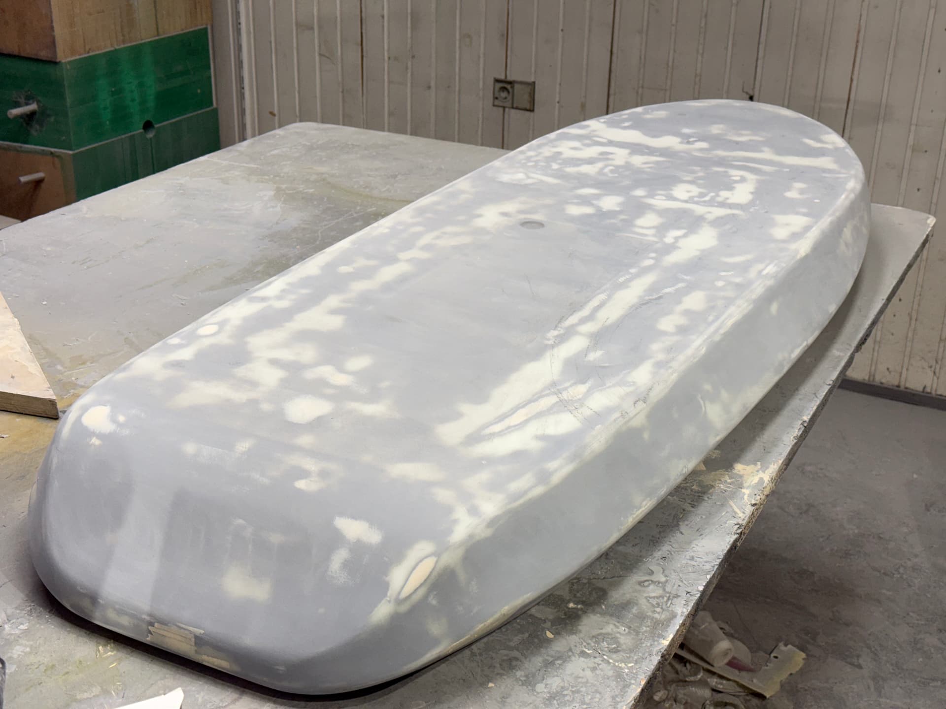
Board Design
The board design is my own.
I initially tried to roughly copy the Fliteboard shape, but as usual the design evolved during the process because of structural constraints:
- battery case size
- component placement
- mounting structure
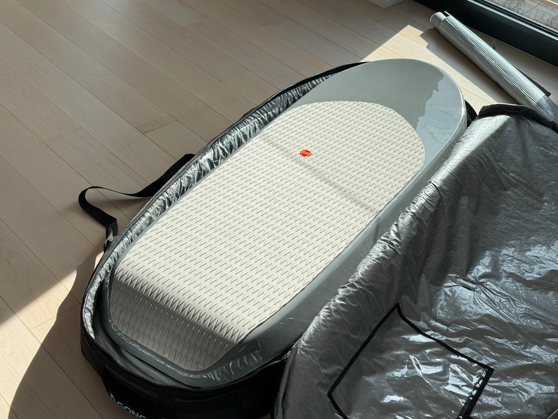
Final dimensions:
- Length: 149 cm
- Thickness: 11 cm
- Volume: ~90 L
I already have the itch to build something much smaller for summer, but since I’ve never actually e-foiled before, I figured starting with something more stable is the smarter choice. Hopefully I’ll get the hang of it quickly.
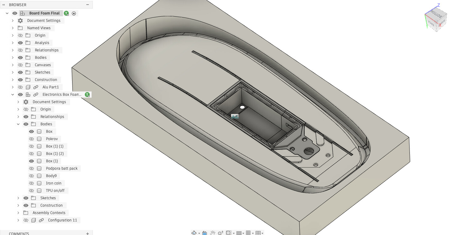
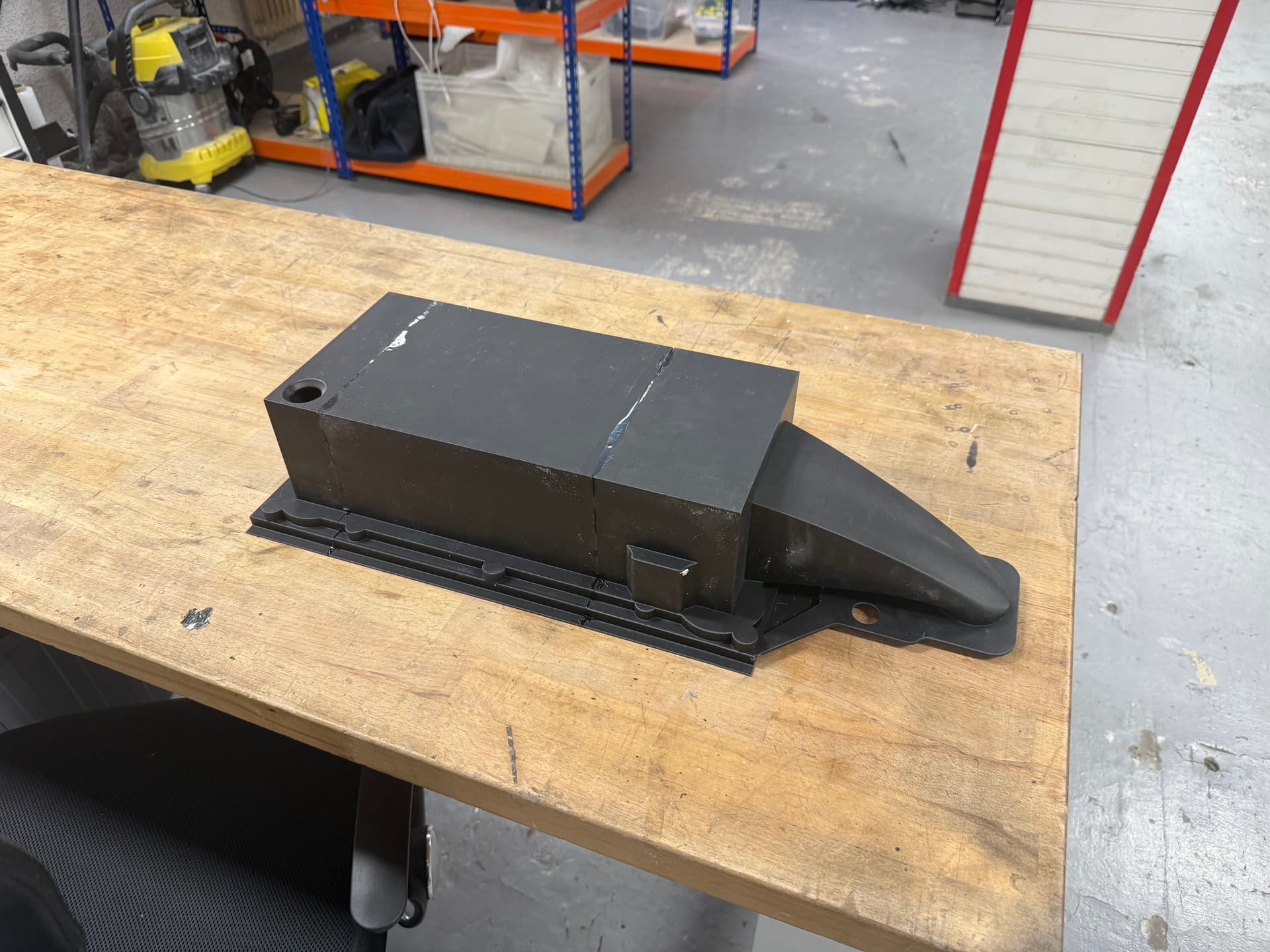
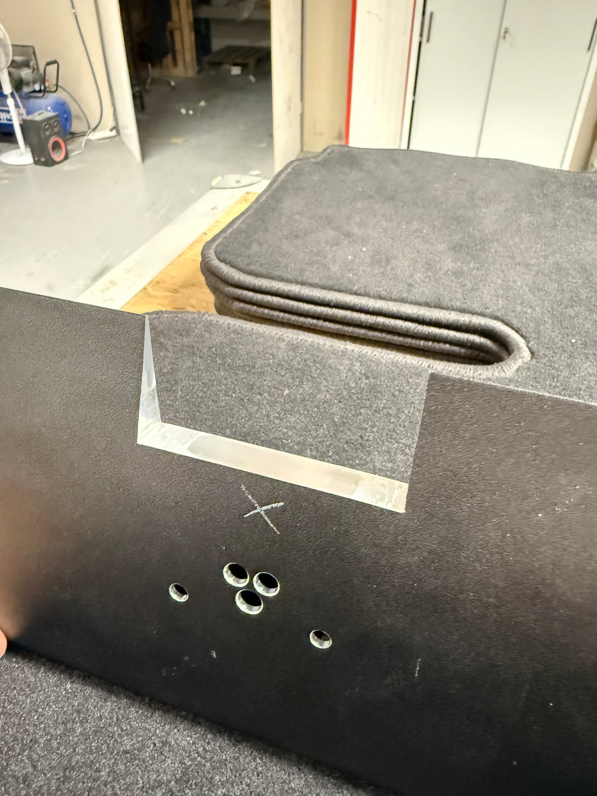
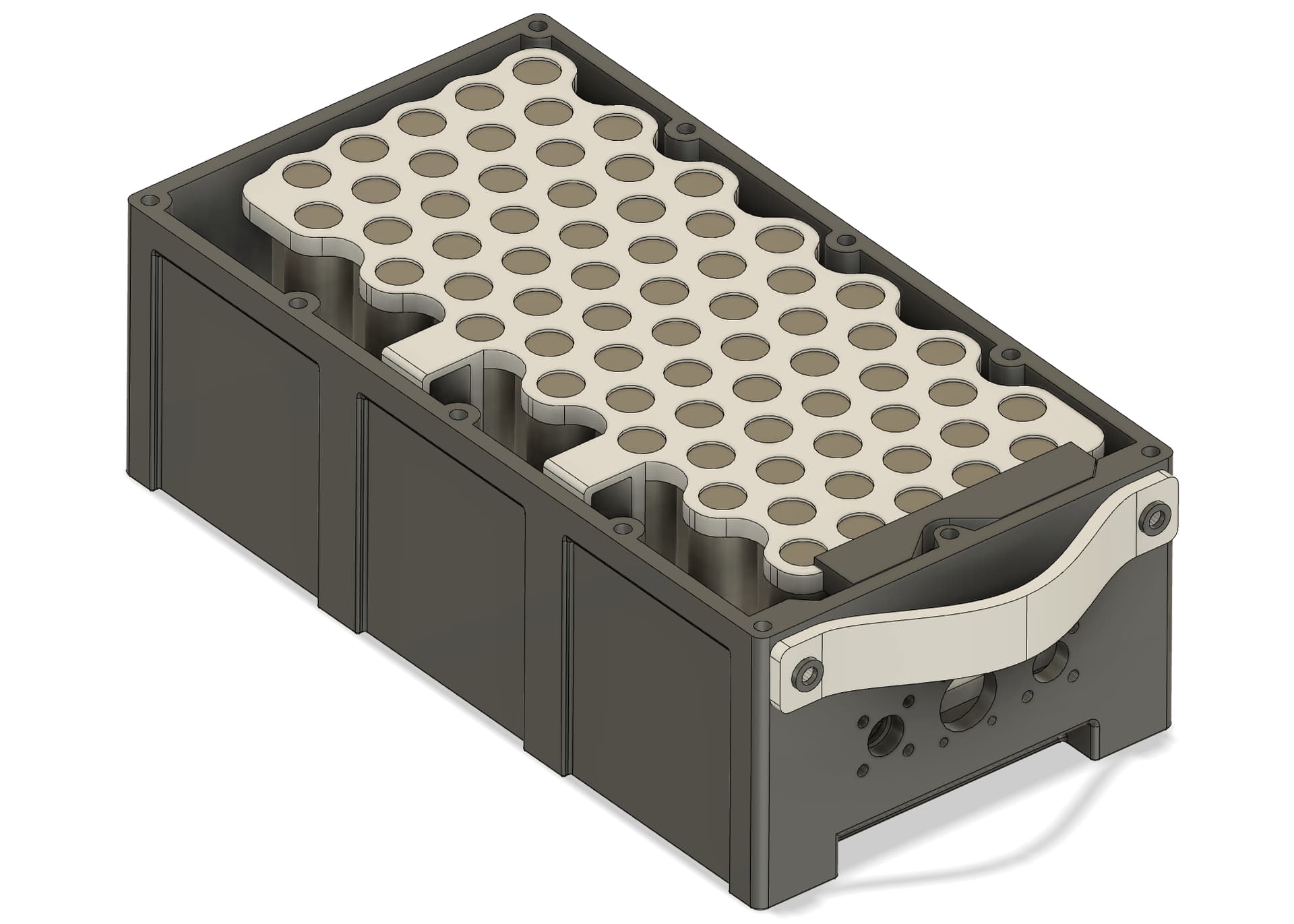
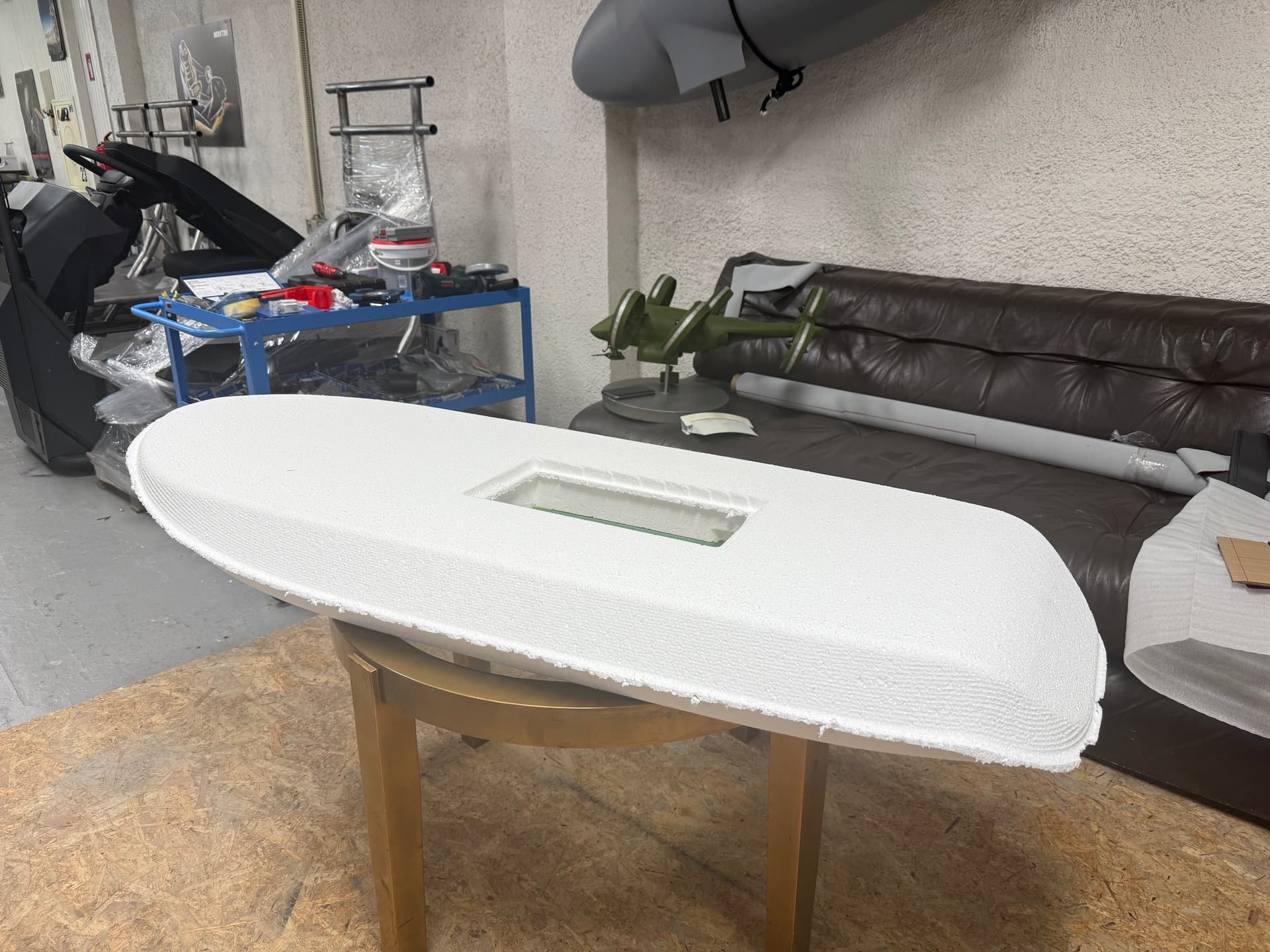
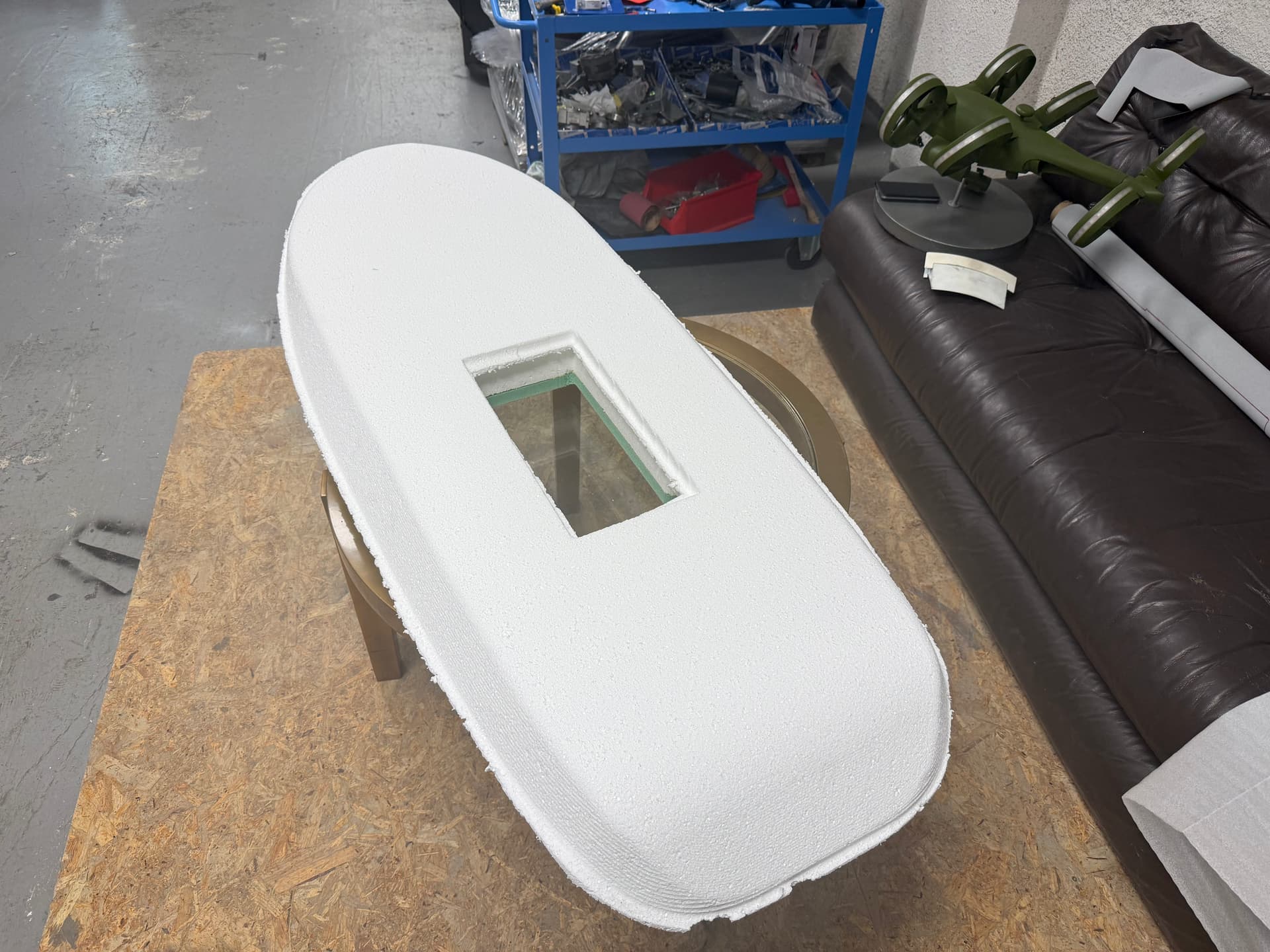
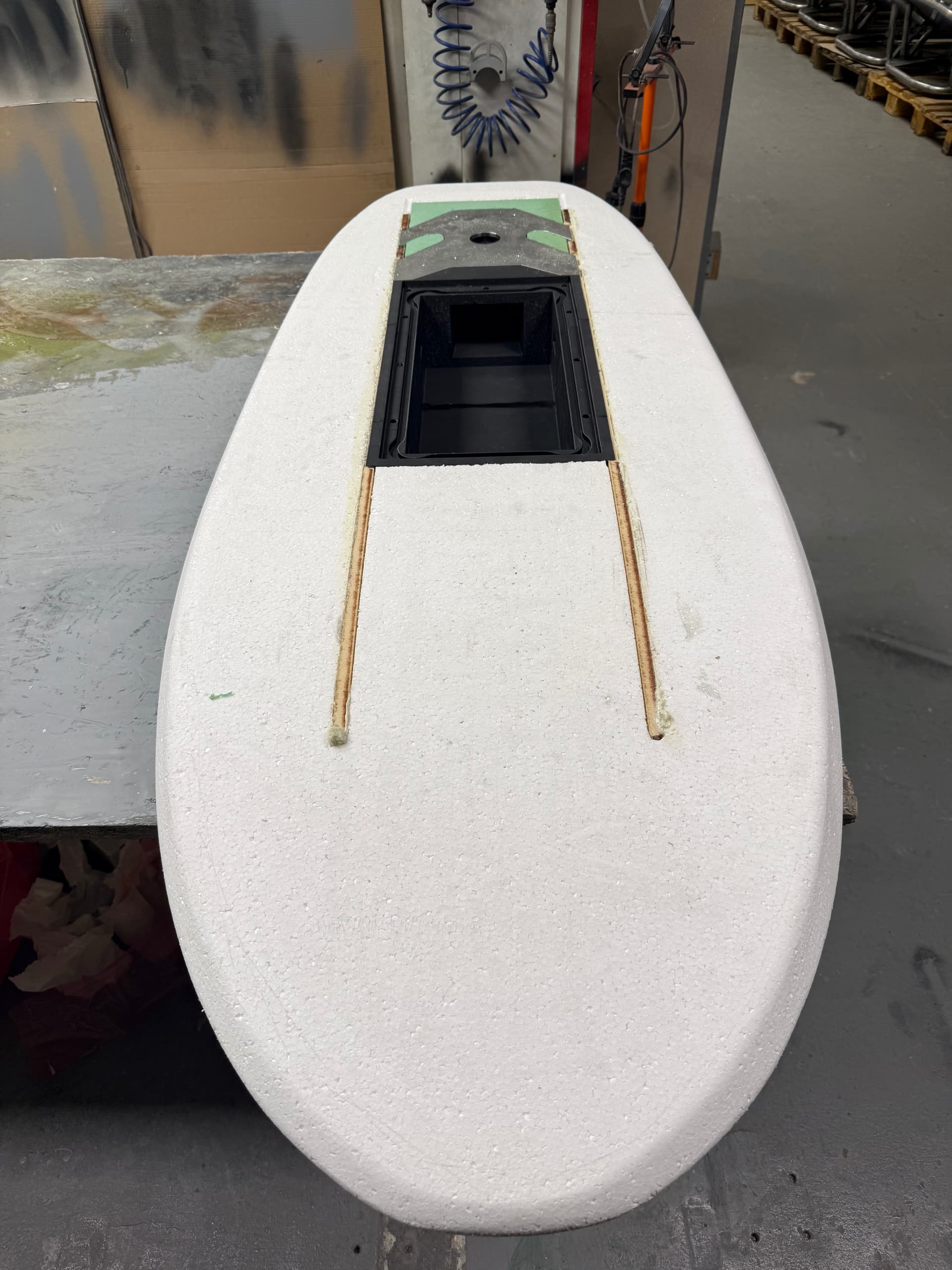
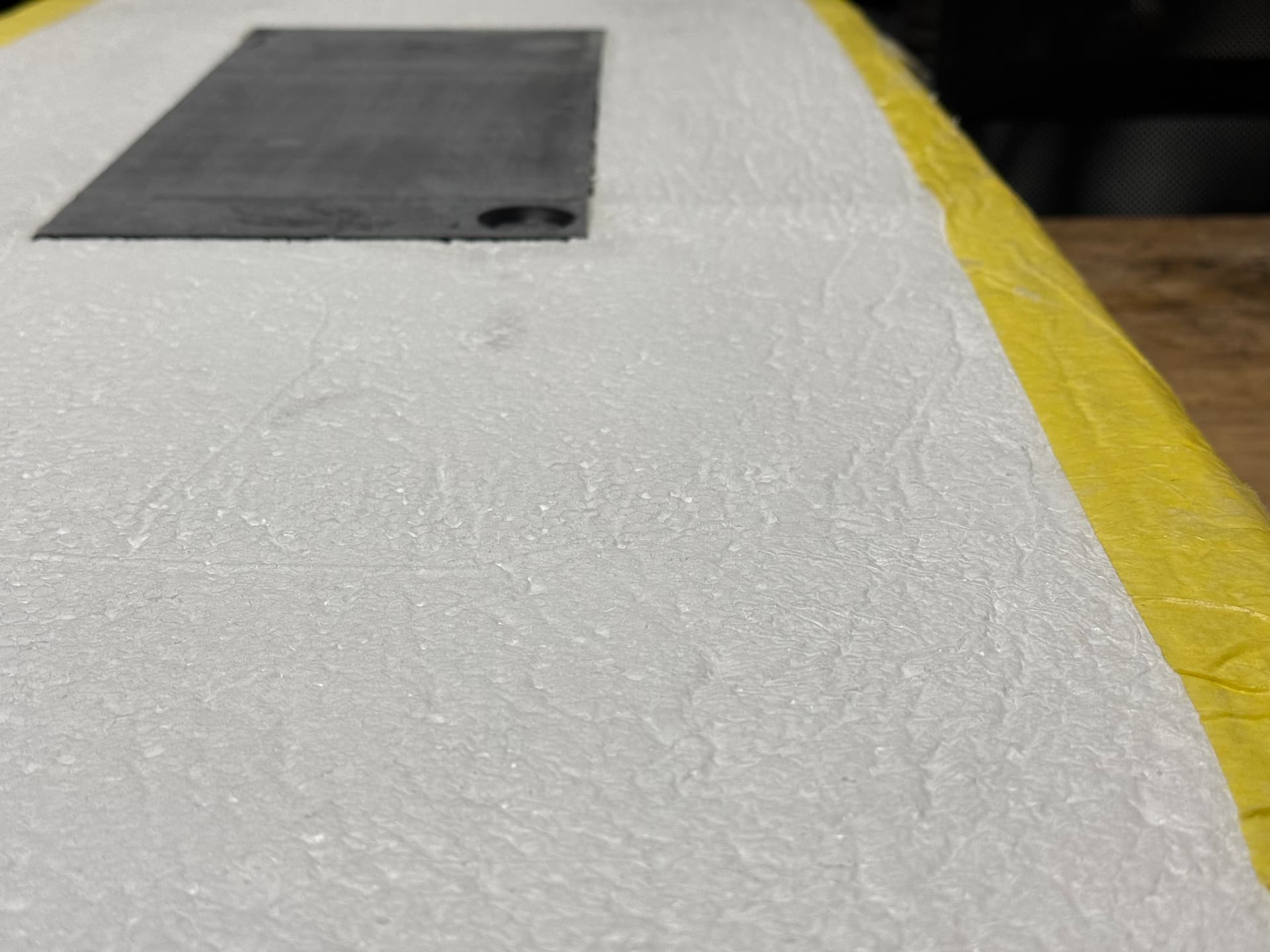
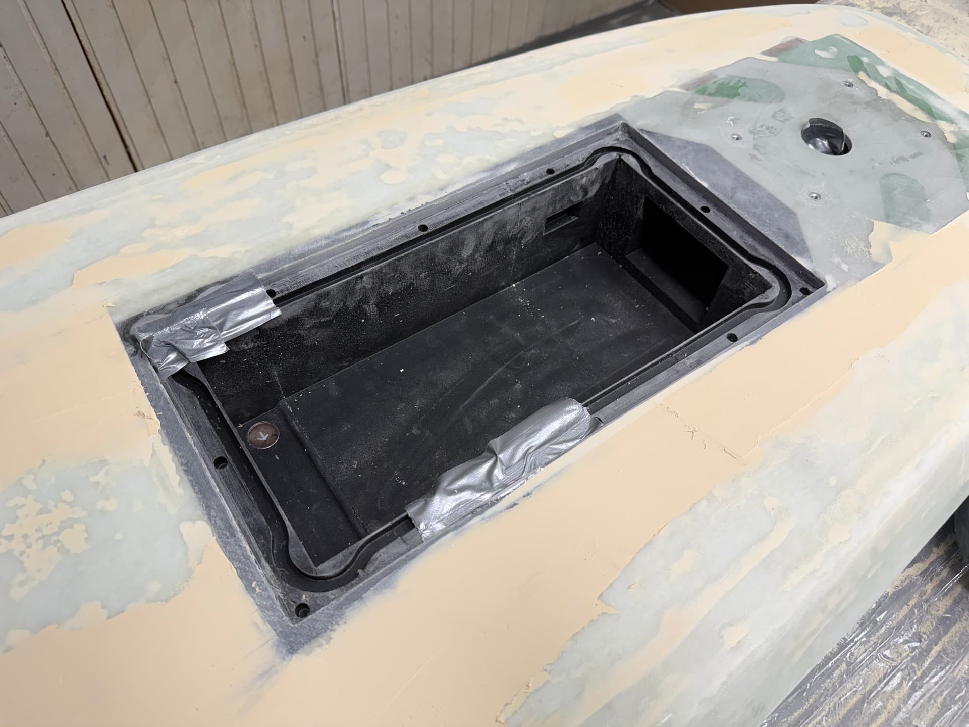
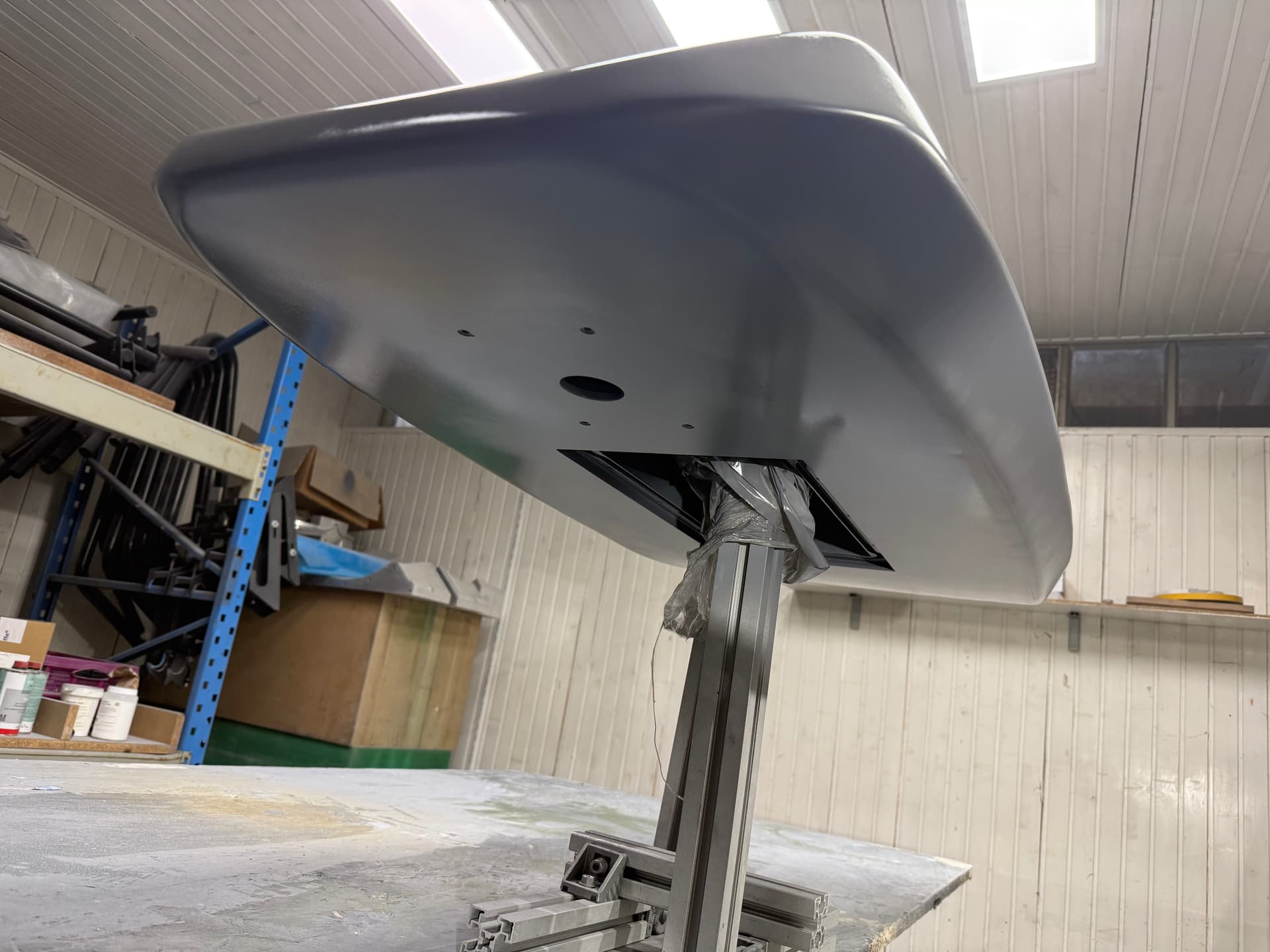
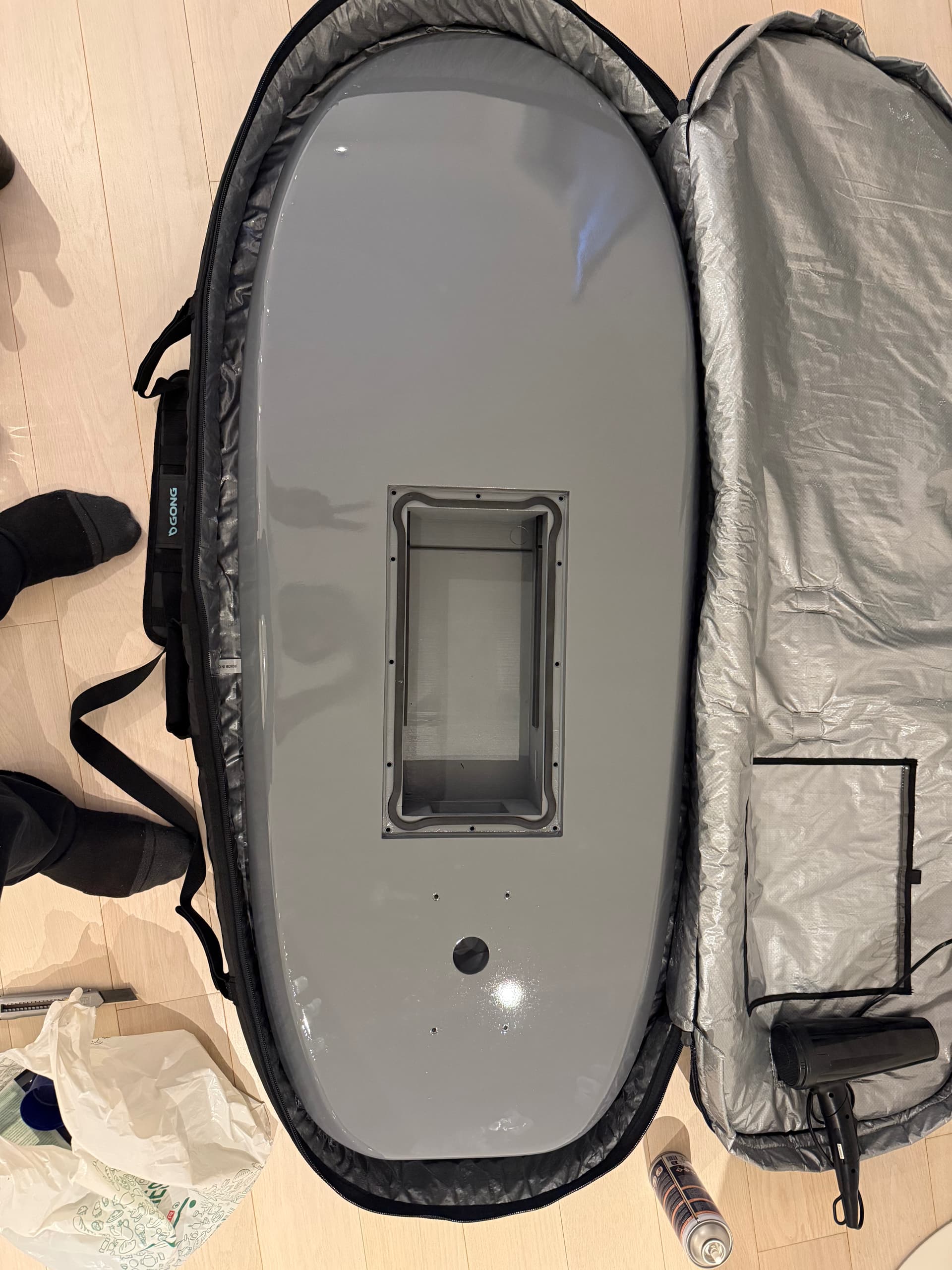
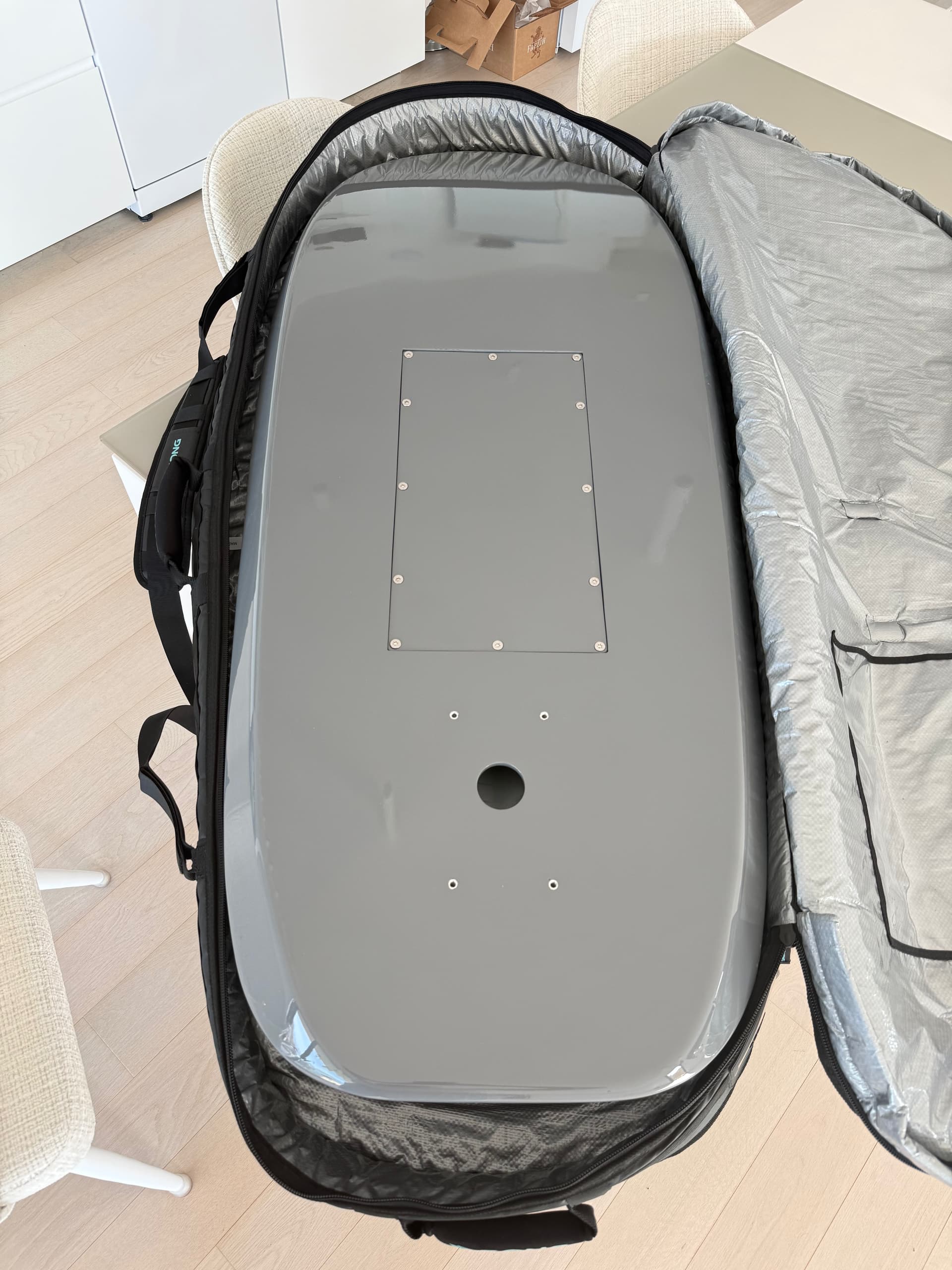
Board Inserts
The board contains two main inserts:
- Battery compartment
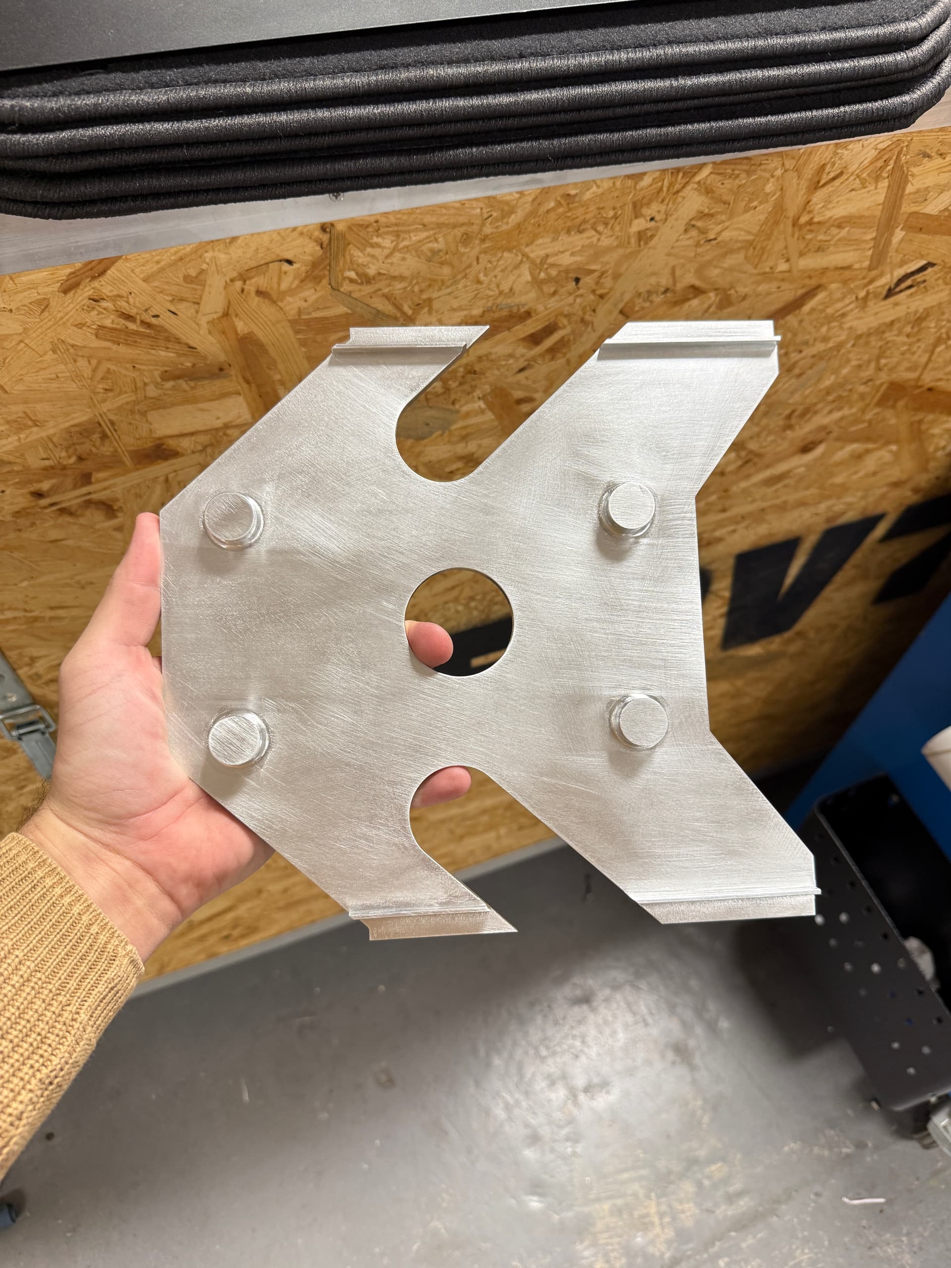
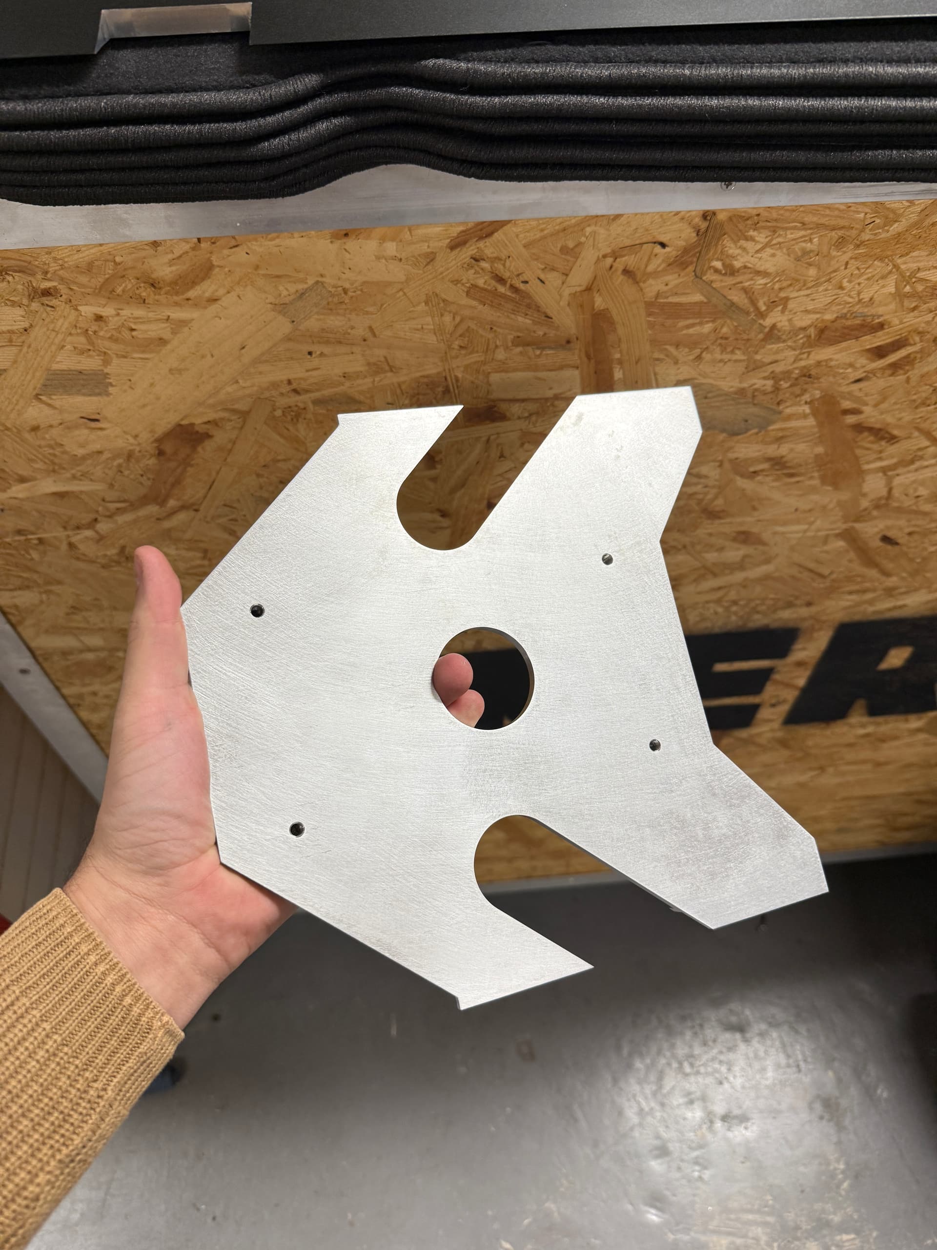
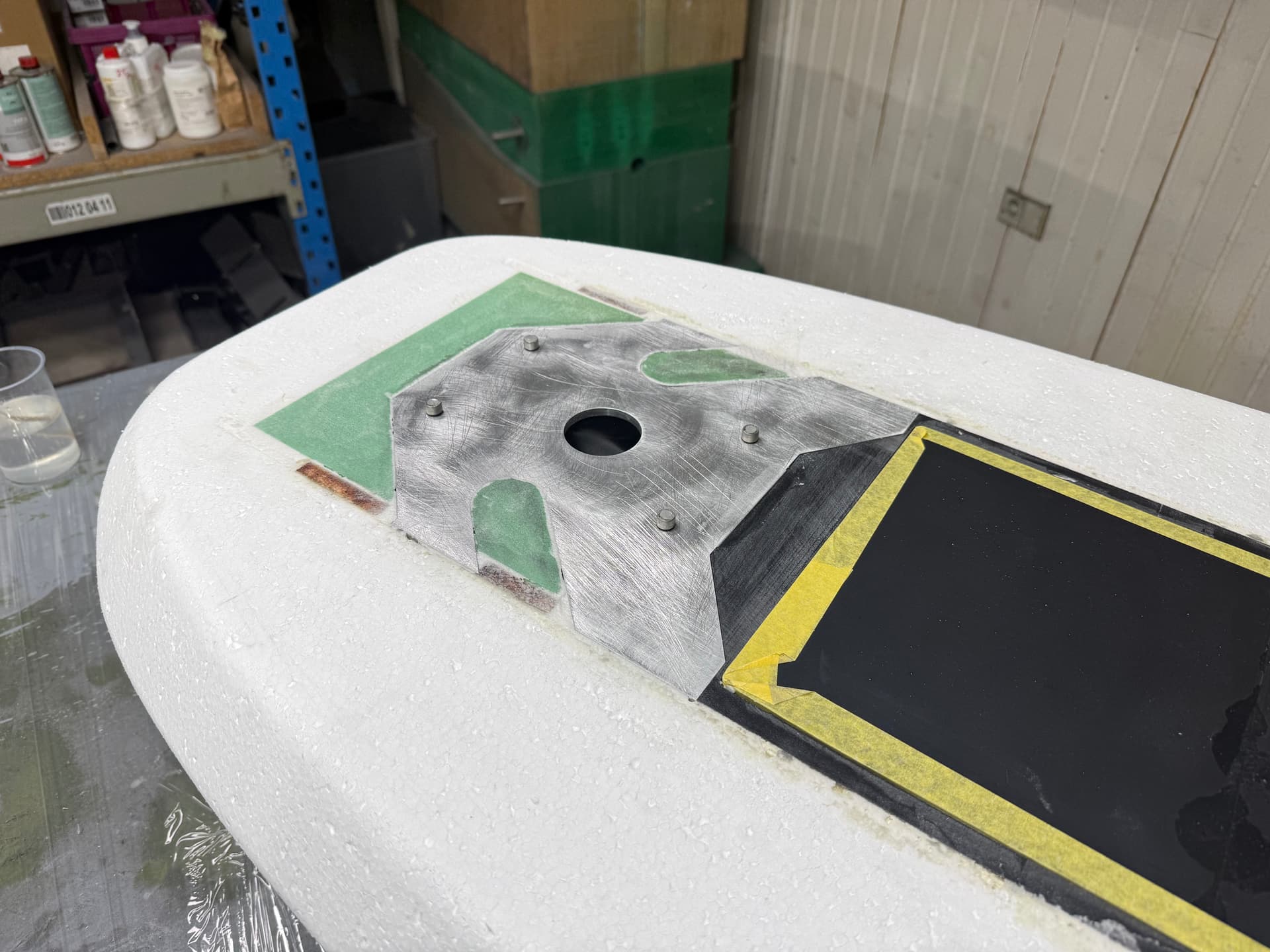
- Mast mounting aluminium plate
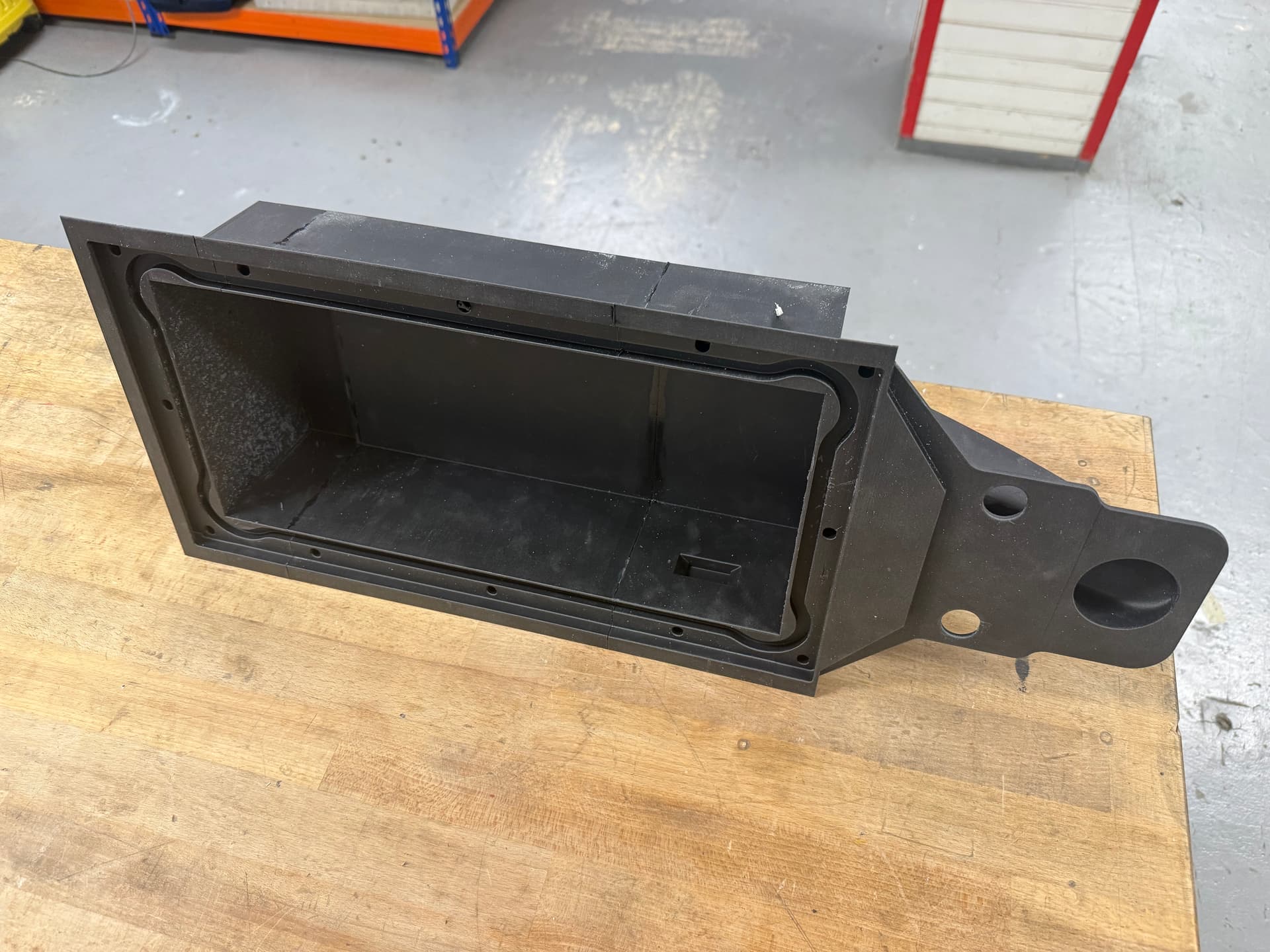
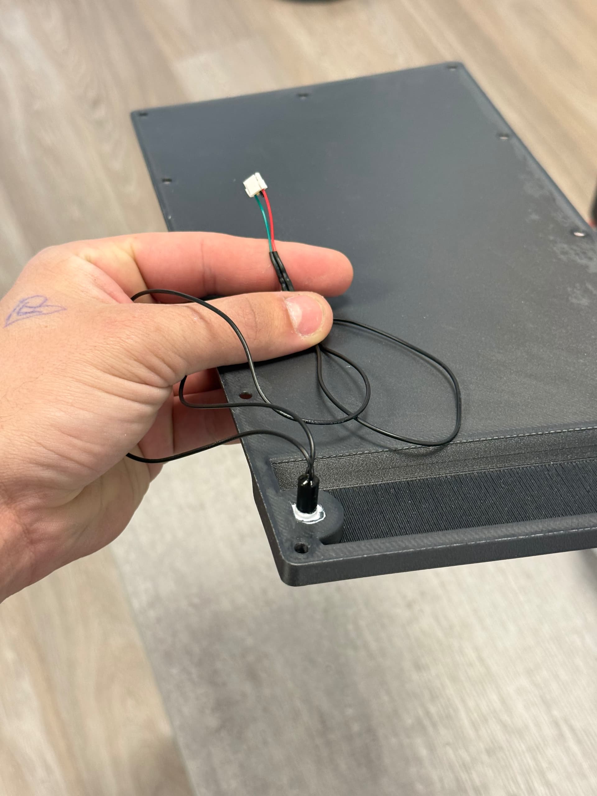
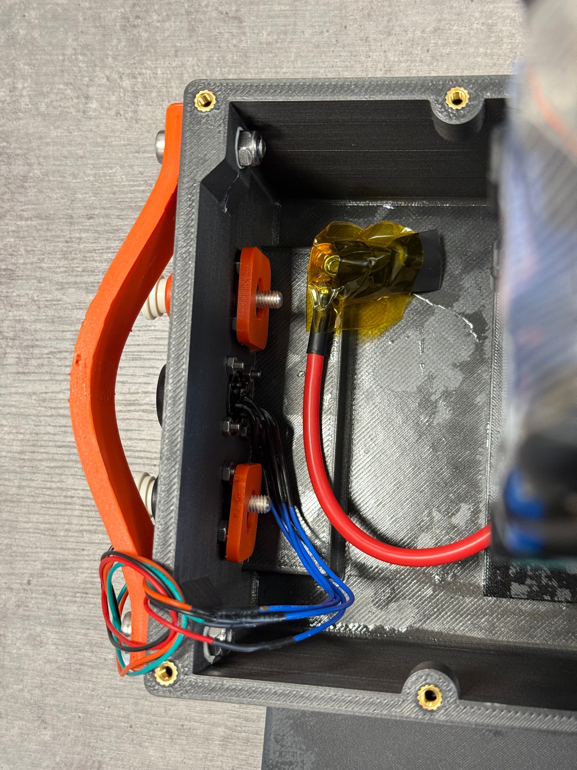
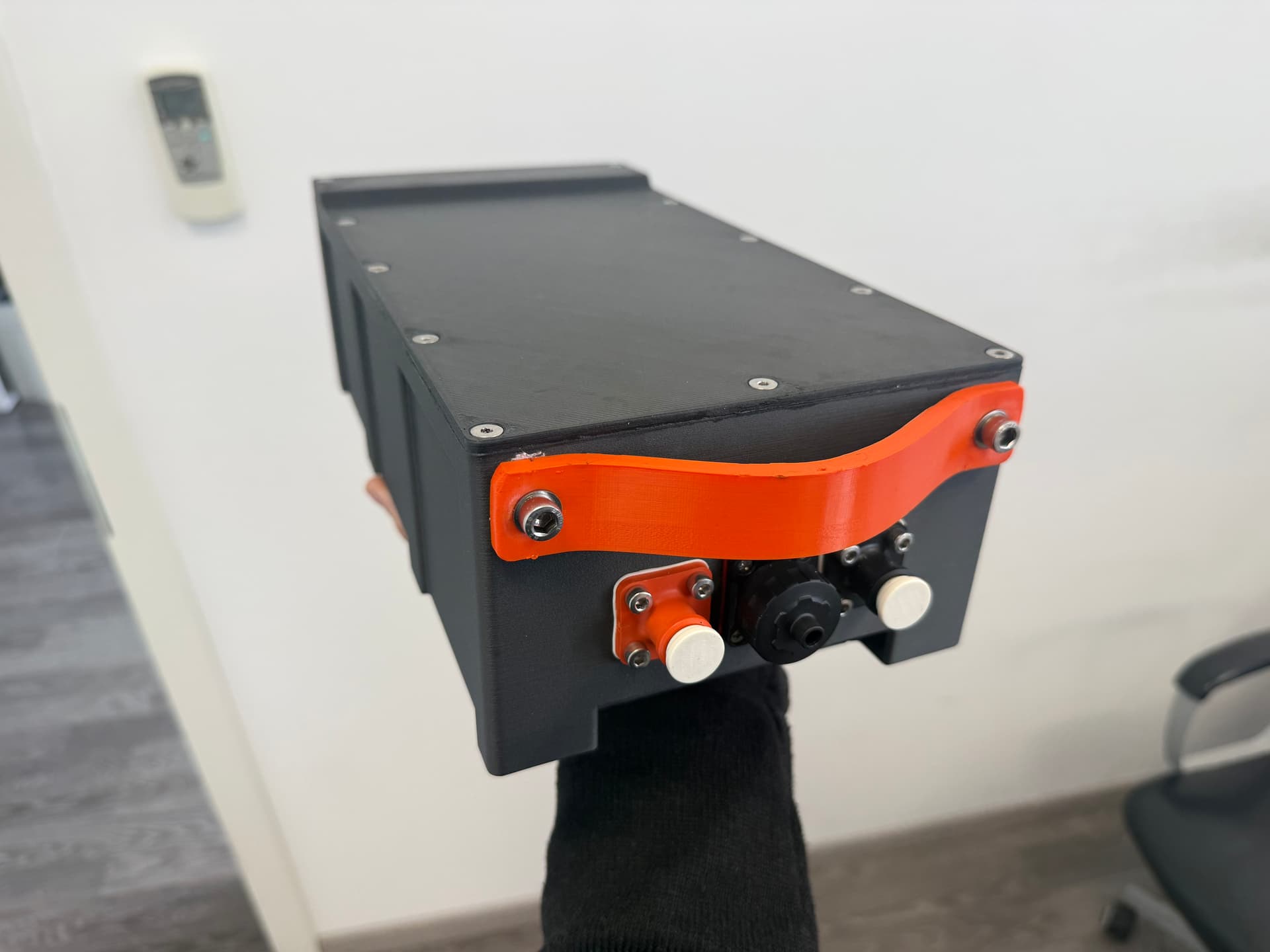
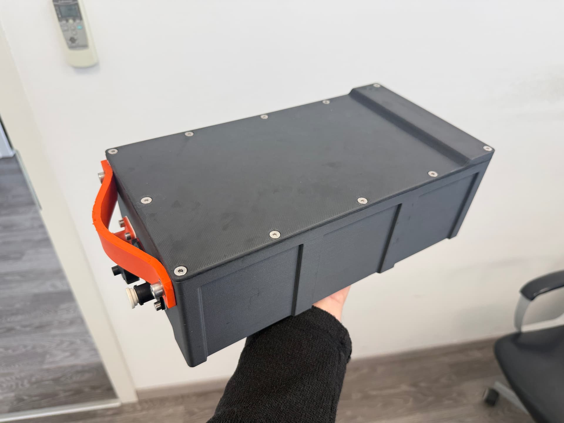
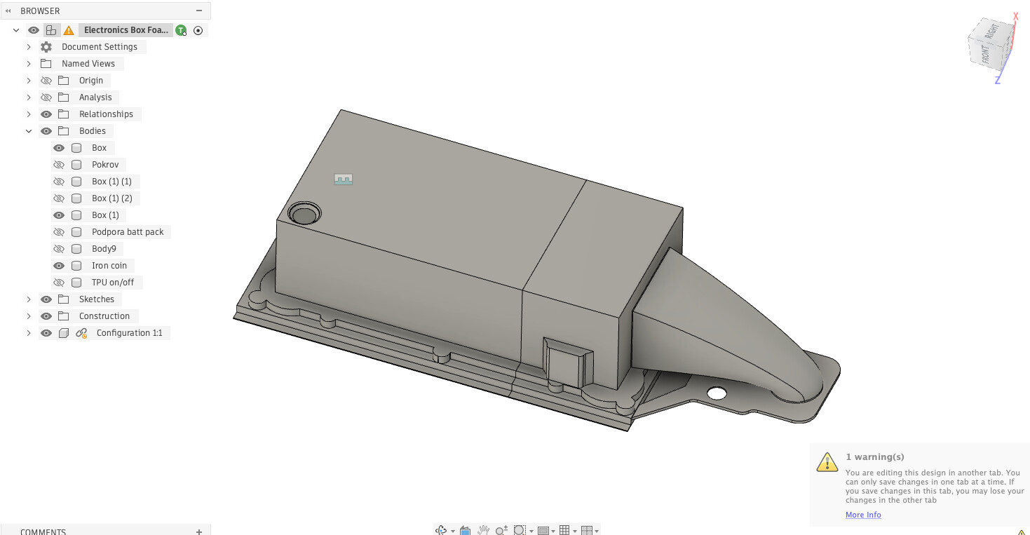
The battery compartment is 3D printed from PCCF.
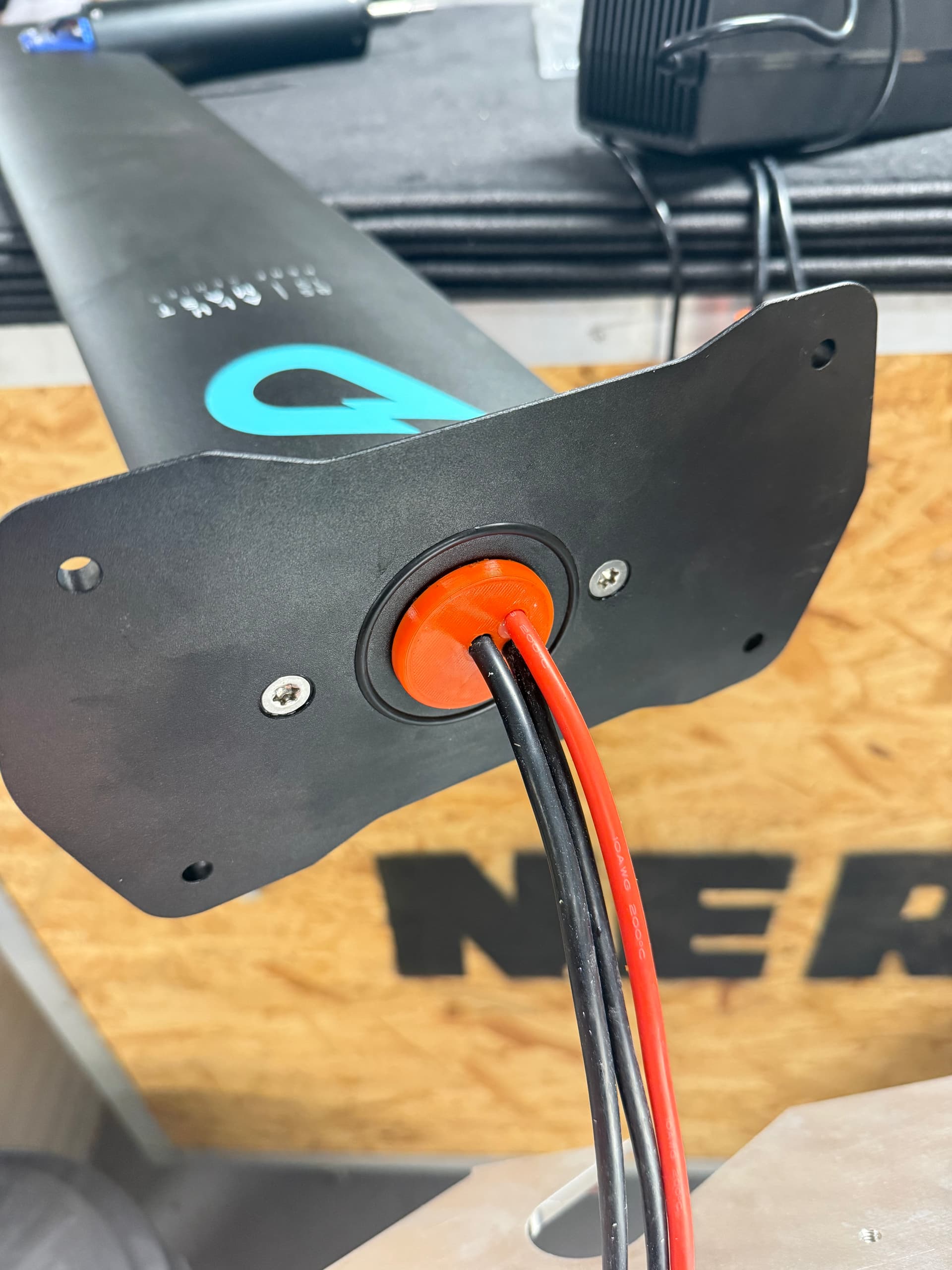
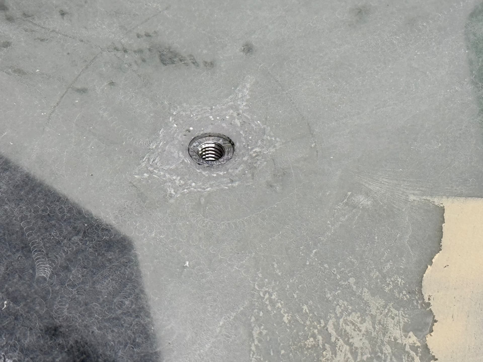
Waterproofing
I experimented with several different designs to seal the battery compartment, but none of them worked reliably enough.
In the end I decided to keep things simple:
Stainless screws + gasket sealing.
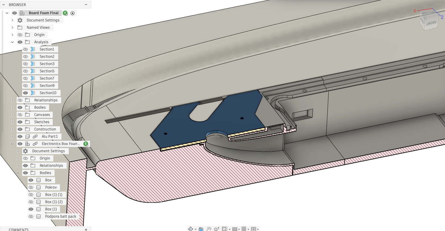
Important detail:
- The battery is inserted from the bottom of the board.
- The battery pack itself is fully waterproof, so even if some water gets inside the compartment it shouldn’t be a problem.
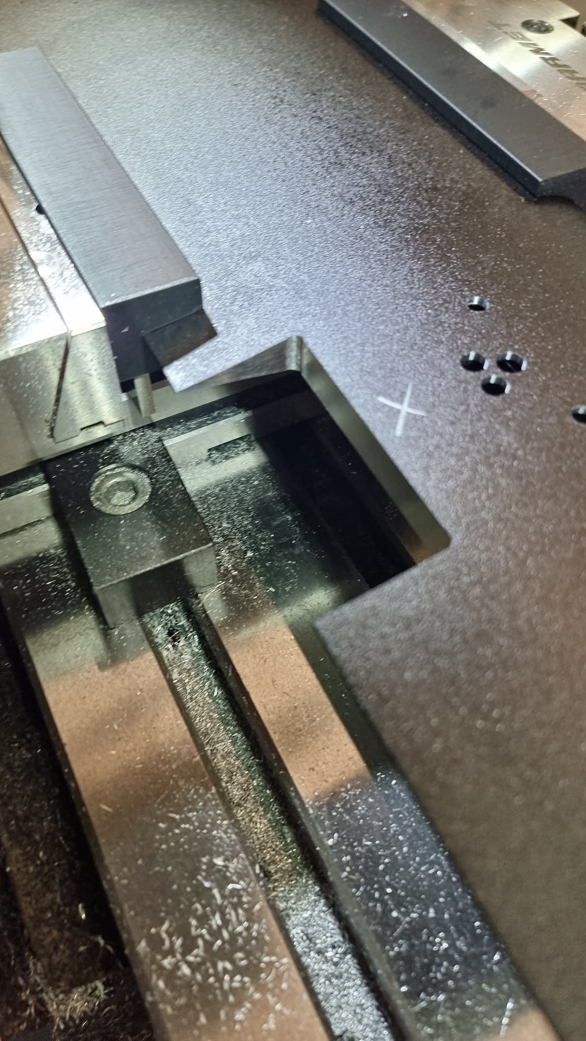
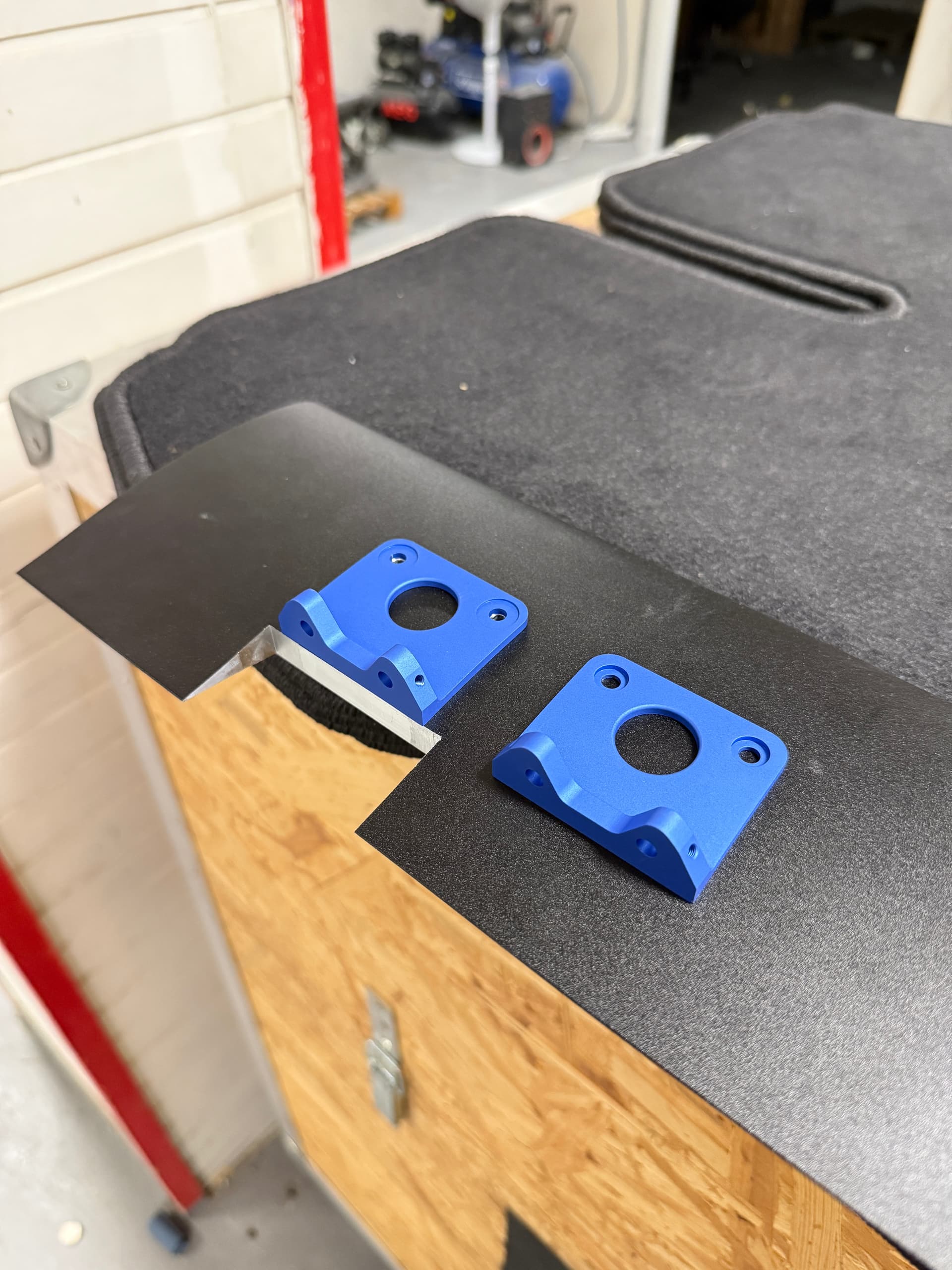
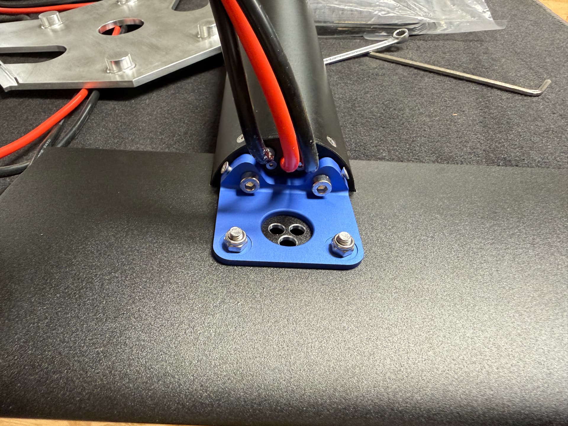
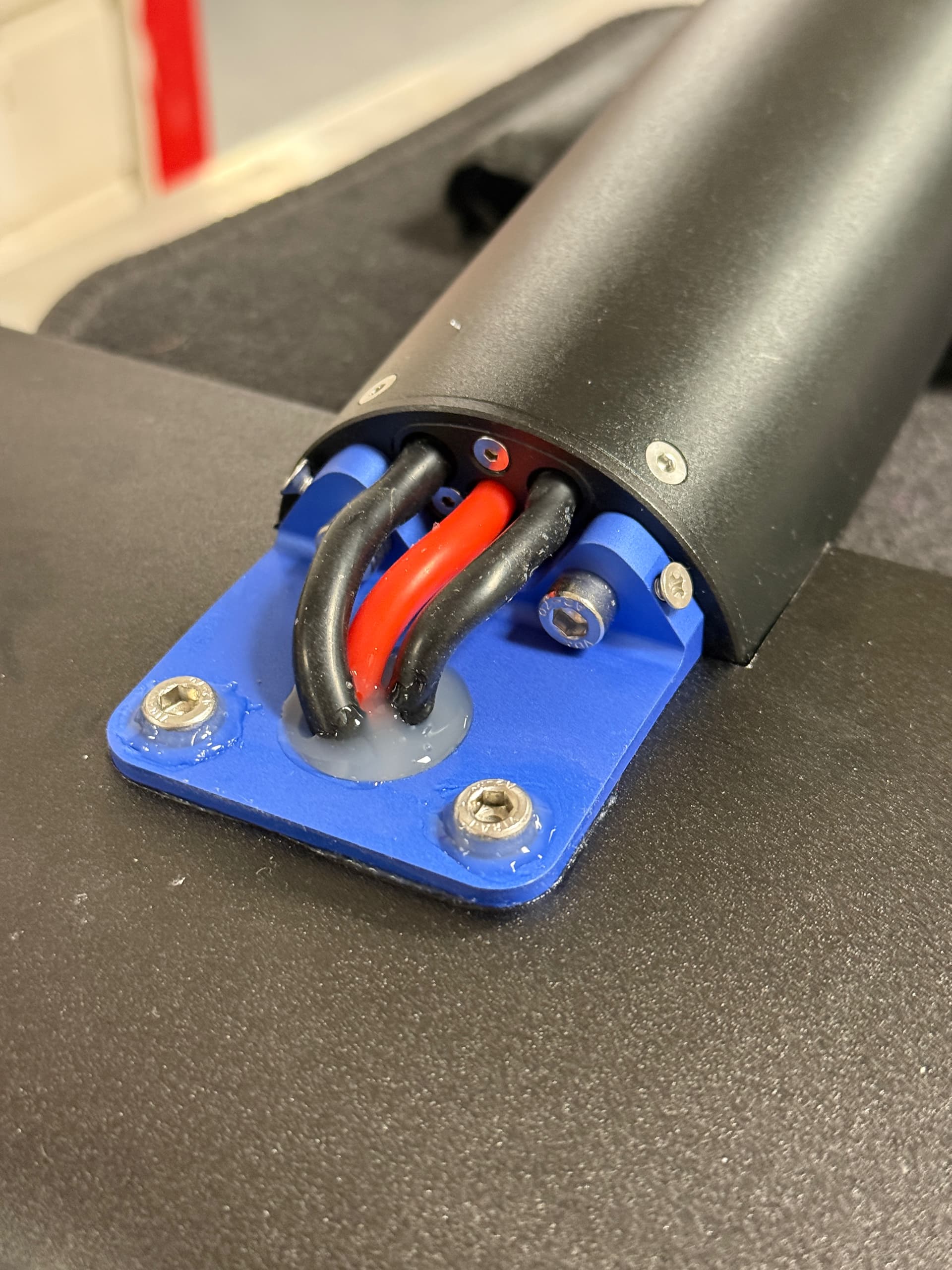
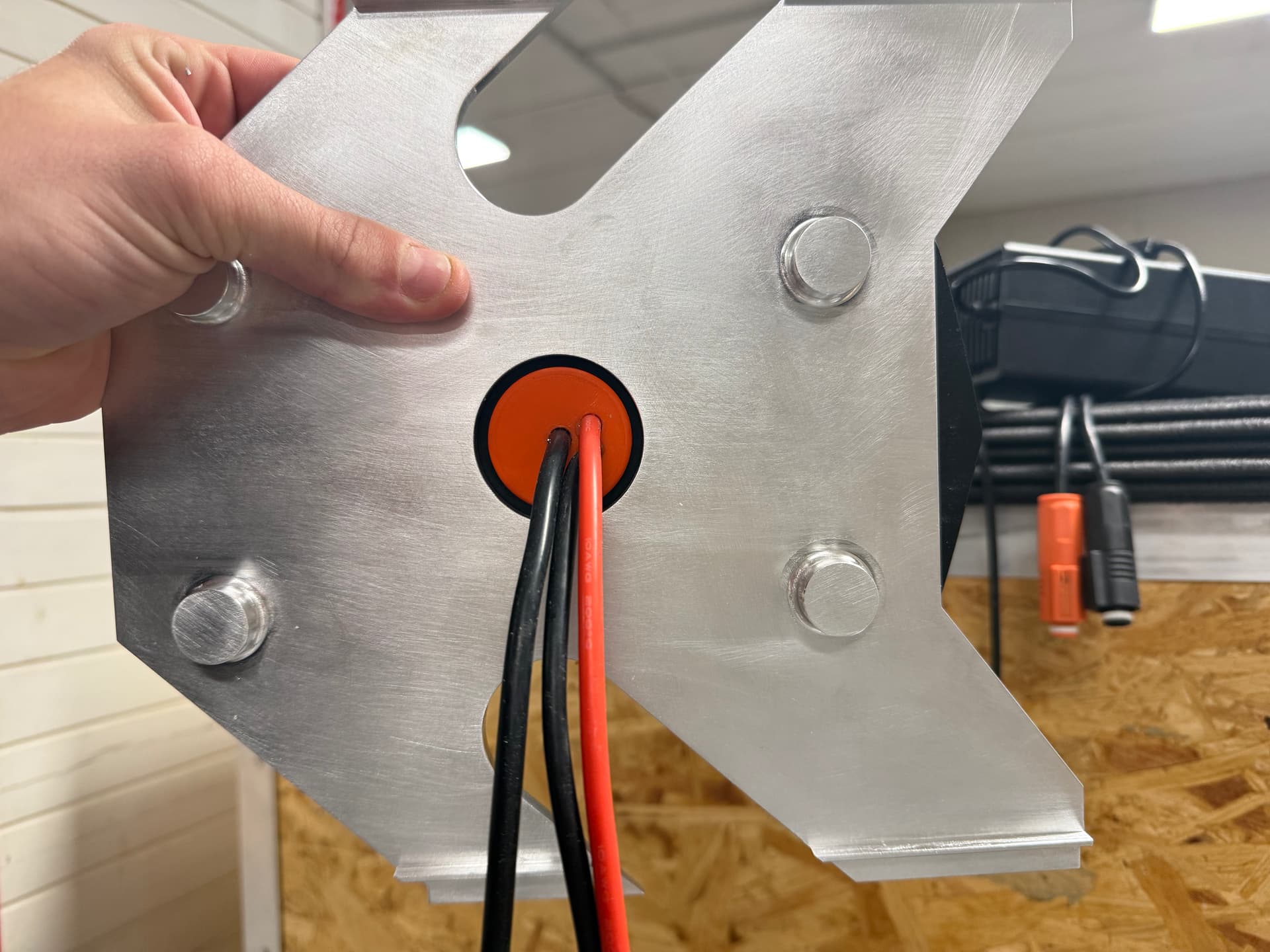
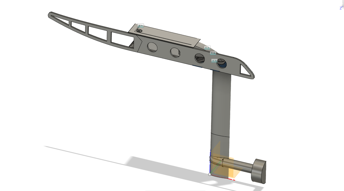
For the mast adapter plate, I machined a groove and installed an O-ring seal, which should keep water out from that interface.
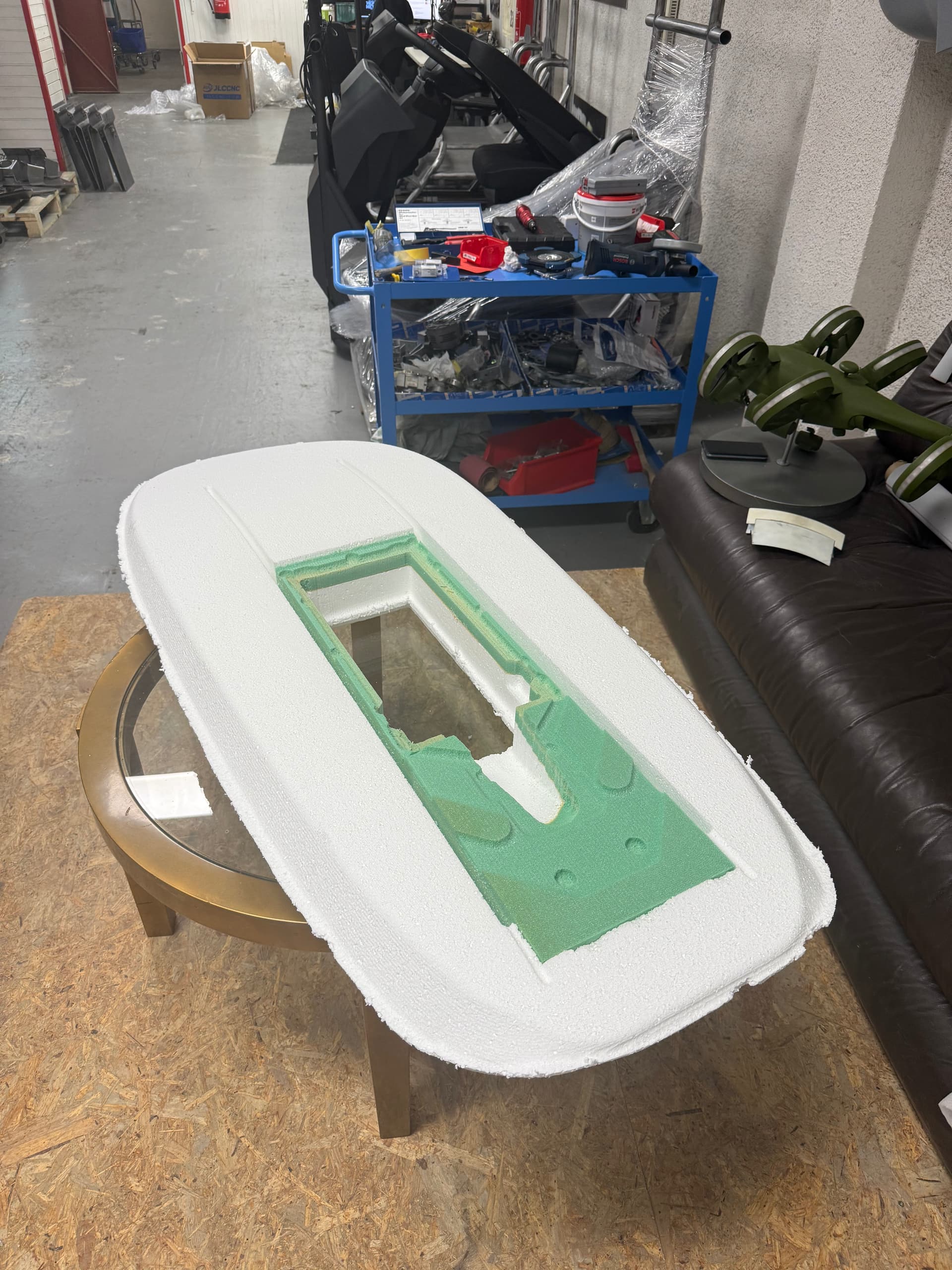
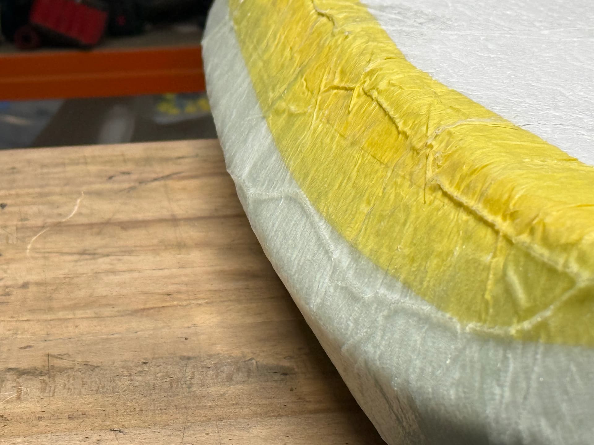
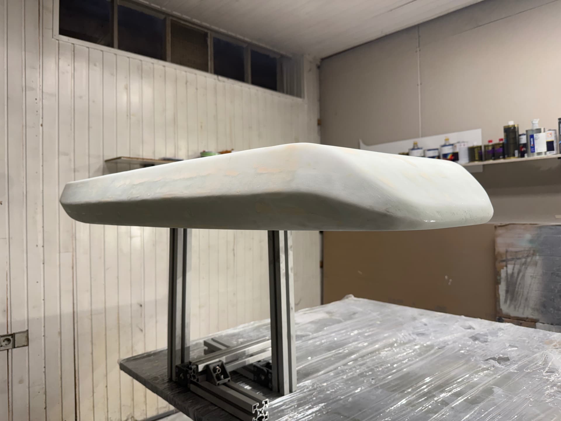
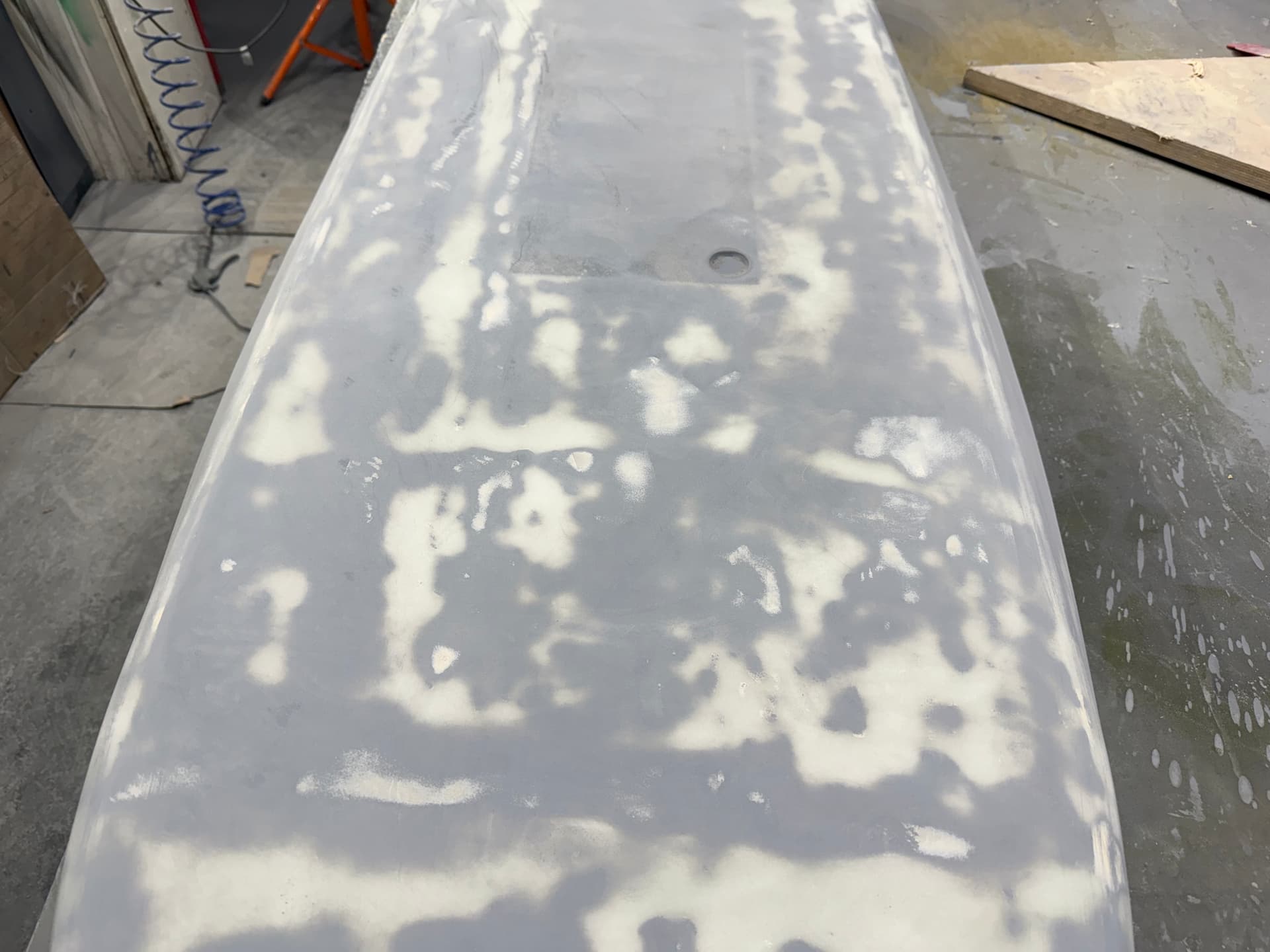
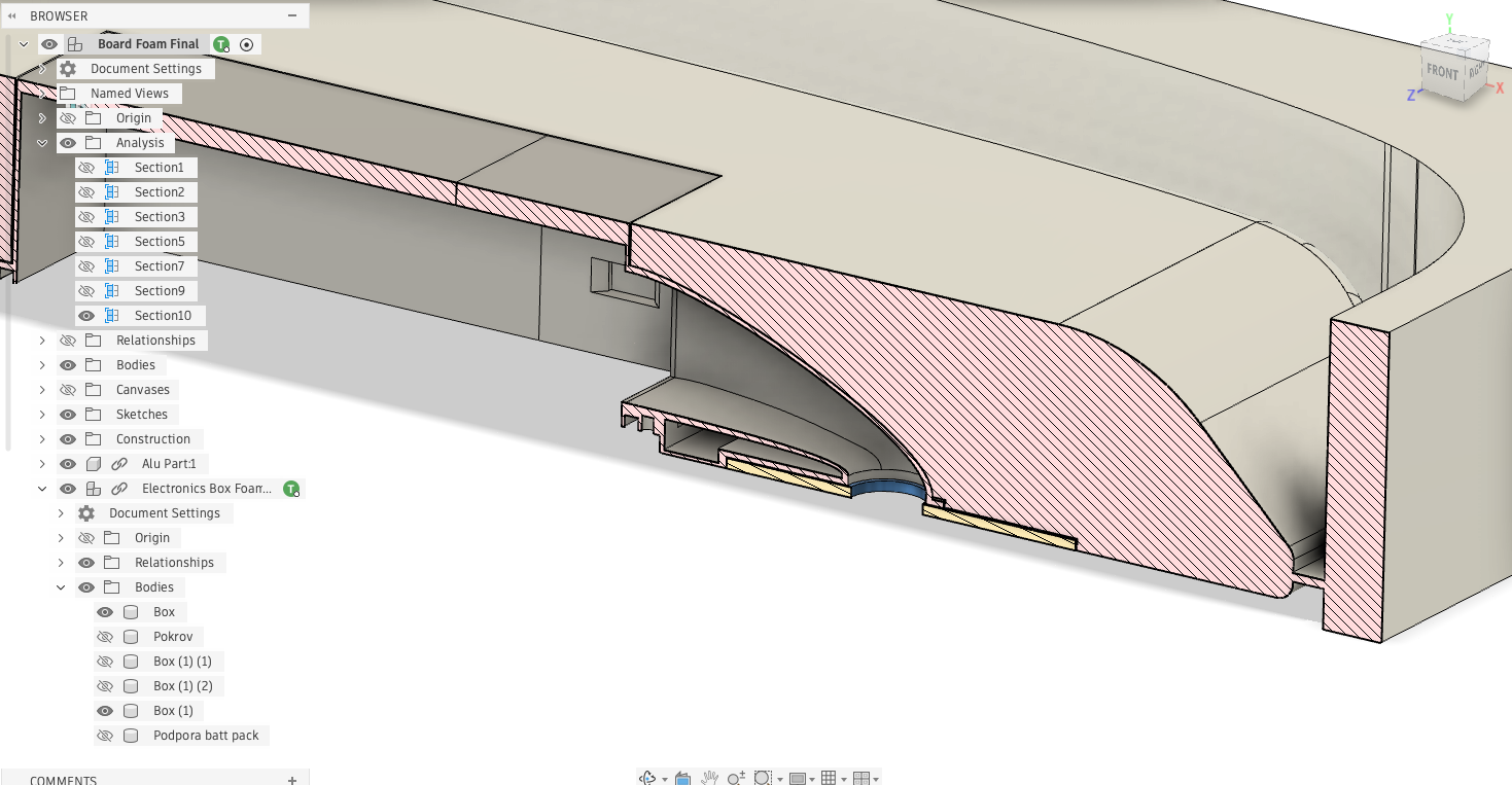
Structural Reinforcement
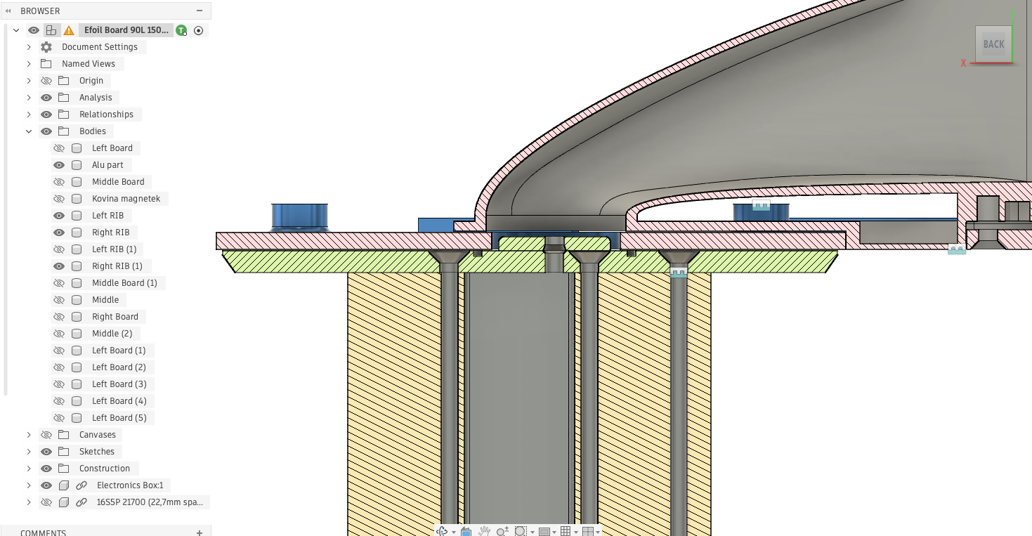
I also paid special attention to how the mast loads transfer into the board.
The forces from the aluminium mast insert are distributed into two longitudinal ribs running along the board.
Each rib is made from:
- 10 mm Airex foam
- Laminated with 80 g/m² fiberglass
This should help spread the load and avoid localized stress around the mast mount. Anddd - totally unnecessary I believe. I just bumped up the weight too much but its all good - a note for next build.
This is how the PCCF battery compartment looks like and also the aluminium board mast insert. Note that both of them mate in a specifict way between eachother and the two ribs - i know overcomplicated.