I need suggestion and somebody who is capable to build Lithium-Ion Battery Pack for E-foil.
Electrical Specifications and Chemistry
The assembly must strictly utilize top-of-the-range cylindrical cells with high capacity and high continuous discharge rates to guarantee minimal voltage sag under load.
• Required Cell Model: Lithium-Ion – Molicel INR 21700 P45B 4500 mAh
• Electrical Configuration: 14S 13P (14 Series, 13 Parallel)
• Total Number of Cells: 182 cells
• Nominal Voltage: 50.4V – 52V
• End-of-Charge Voltage (Max): 58.8V
• Total Nominal Capacity: 58 Ah
• Total Energy Capacity: ~3.53 kWh / 3.64 kWh
3. Geometric and Mechanical Constraints (Mandatory)
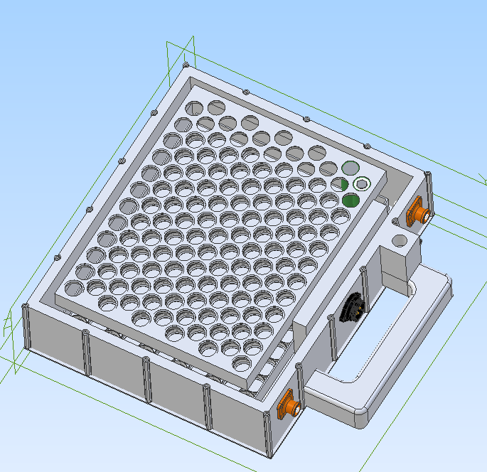
The battery pack must be housed inside an existing watertight enclosure. The spatial layout must maximize the footprint area.
• Internal Usable Dimensions of the Enclosure: 290 mm (Width) x 340 mm (Length) x 80 mm (Height). The sides ((290 \times 340\text{ mm})) of the enclosure will be aluminum, while the rest will be ABS.
• Cell Layout: A honeycomb (staggered/nested) configuration is mandatory to optimize space.
• Component Orientation:
o 290 mm Axis: Stacking of 14 cells in width (theoretical bare cell clearance ~289.3 mm). The use of plastic inter-cell spacers is forbidden on this axis due to near-zero tolerances ((\leq 0.7\text{ mm})).
o 340 mm Axis: Stacking of 13 rows in depth (theoretical clearance ~257.5 mm).
• Clearance Space for Electronics (BMS Compartment): Approximately 82.5 mm of free space remains along the length axis ((340 - 257.5\text{ mm})). This header compartment must house the BMS, structural wiring, and safety systems.
• Maximum Allowed Height: The cells (70.6 mm) leave a vertical margin of ~9.4 mm. This space must accommodate busbars, upper dielectric insulation, and anti-vibration compression material.
4. Interconnection Architecture and Busbars
The cross-section and geometry of the connections are critical to prevent localized thermal stress.
• Busbar Material: Shaped pure copper plates, laser-cut or CNC-machined (Recommended thickness: 2.0 mm, minimum equivalent width to ensure a current density (\leq 4\text{-}5\text{ A/mm}^2)).
• Load Distribution (Take-off Points): The main power terminal plates (B+ and B-) must not use a single connection point.
• A minimum of 3 symmetrical welding/take-off points along the plate is required to uniformly distribute current flow and prevent thermal imbalance between core and peripheral cells.
5. Insulation System and Mechanical Safety (Anti-Shock)
• Structural Fixing: Cell bonding using NEUTRAL (Alkoxy) thixotropic structural silicone with high thermal conductivity. The assembly must form a single monolithic block, eliminating any wrap-on-wrap friction.
• Electrical Insulation:
o Fish paper (Barley Paper) rings are mandatory on the positive terminal of every single cell.
o Vertical dividers and horizontal covers made of FR4 / G10 fiberglass sheets (minimum thickness 0.5 mm) to prevent mechanical punctures or accidental contact between adjacent busbars under vibration.
o Outer wrapping of the cell block using high-temperature Kapton (Polyimide) tape.
• Vibration Damping: Insertion of a closed-cell foam layer (Neoprene or EVA) at the top and sides to ensure constant pressure under the enclosure lid.
6. Control Electronics (BMS) and Wiring
• BMS Specifications: Integration of a Smart BMS (with Bluetooth/App and/or CAN/RS485 communication protocols) rated for 100A continuous discharge and equipped with accurate active or passive balancing.
• BMS Spatial Dimensioning: The BMS must fit within the 82.5 mm usable header compartment, thermally and mechanically isolated from the cell block by a rigid FR4 bulkhead.
• Required Safeguards: Overvoltage, undervoltage, overcurrent (charge/discharge), and short circuit protection.
• Temperature Probes: Configuration with at least 2 NTC probes embedded in the most thermally critical areas (center of the battery pack).
• Signal Wiring: Balance wires (sense wires) must be neatly organized, protected by an anti-chafing braided sleeve, and securely fastened to prevent dynamic movement.
7. Testing and Delivery Requirements
In the proposal, please specify the end-of-line tests included, such as:
• Dielectric insulation test (Hi-Pot test).
• Verification of total internal resistance of the pack (IR test).
• Testing cycle and charge/discharge report under real load (at least 1 full cycle at 50A).
You should probably post where you are located, then just ask for any recommendations for builders or vendors others might recommend. Shipping battery packs is not easy, so unlikely a forum member wants to directly help build unless they are local to you or have a small business that builds and ships packs.
Dumping all that AI output isn’t necessary, way too much detail nobody really needs to read.
State your location and just say which Capacity, Voltage and Peak current the pack should have. You can give a maximum size l-w-h and weight maybe. Maybe even specify your favorite cell. Let the one building it (the “pro”) come up with a recommendation on layout, busbar, …
Take their offer an paste it into AI to verify if you want
If you want to actually gain the knowledge yourself, I am happy to share my video on the topic:
thank you for the correction. sorry for my ignorance but is for that I am looking for help. Samsung 50S cells do not last so much. after not so many charge\discharge it loose power
Sorry, chiming in here cause i got a “ping” since my link got mentioned:). I do not know where you got your info about cells. I have used 50s cells in a Vesc Onewheel build for over 3000km under very harsh conditions, cells still charged and balanced nicely at 4.17v. And this was “only” a 2p pack…for the amount of parallel we use in efoil these cells will not suffer at all.
Most efoil packs (production models) have inferior cells with lower discharge rate compared to 50s. I can say i have quite extensive experience with them on Onewheel, charging and discharging them to the max, monitoring their behavior using a high-end bms, and in use conditions where temps got high enough to overheat my vesc and motor, and temps below to -10C.
Hence i opted for them for the efoil, too bad i aborted that project…
I have used P42A, P45B and Samsung 40T for eFoil, P45B and P50B for Onewheels. Molicel are realy good, my P45B packs are 3Y old and still balace to 1 digit mV in a 7S11P config.
I also use RS50 for an assist in 12S2P and 12S3P config, they perform well for packs with low P, also great for Onwheels, probably overkill for an eFoil with a larger pack. You don’t need that high discharge per cell. Low resistance is still nice, you won’t get much voltage sag on high currents. Don’t now about long term behavior of the RS50, so far they still balance nicely but they only have about 10 charge cycles.
My design based on ludwig_bre inspiration below - it is 12S11P (originally wanted 14S9P, but found it hard to fit under my board and 3D printer contrains)
This design is 340x290 (plus handle) and it feels tight.