Nice job!
For lathing down the shaft you could go for the ‘rough’ method, though it worked fine for me;)
![]()
Nice job!
For lathing down the shaft you could go for the ‘rough’ method, though it worked fine for me;)
![]()
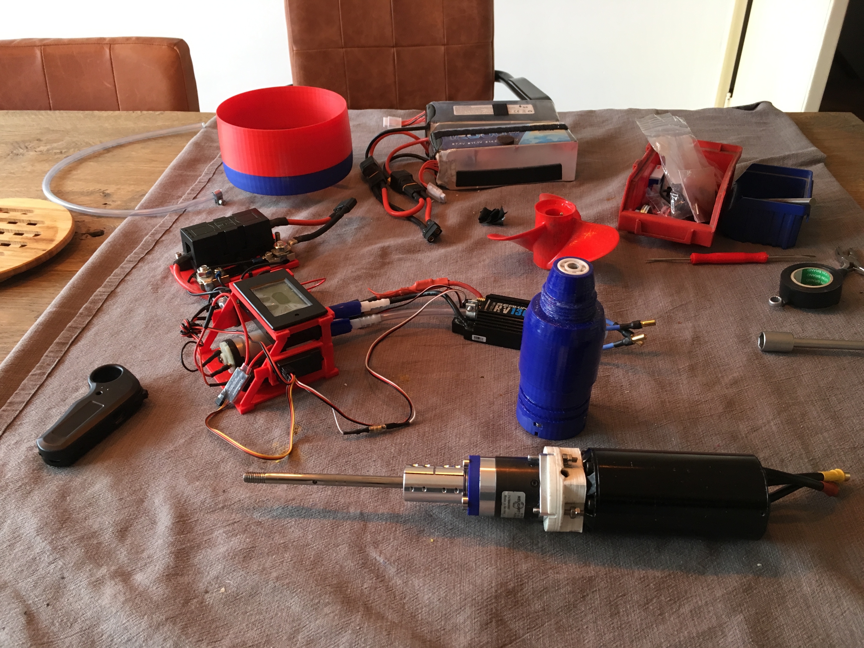
UPdate 3,
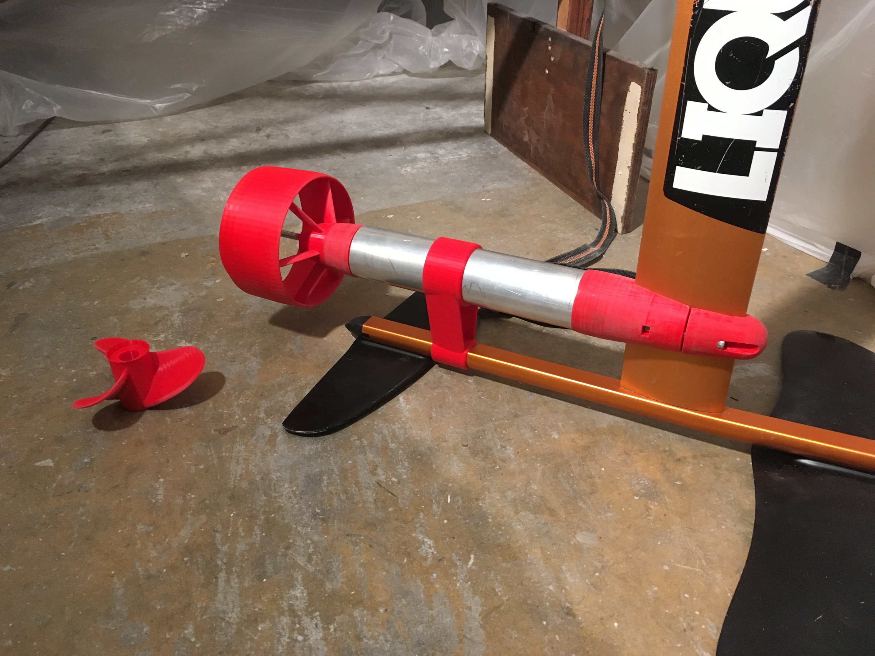
I cut the alu pipe to length today. I don’t want to cut the motor cables so, to compensate for the extra length I printed this support. On the forum I saw somebody drilling a hole in the fuselage to mount a similar support. I did not feel so comfortable with that idea so I took a photo of the cross section of the fuselage and after a few prints I had a very tight fit, so it is can take some lateral loads in addition to the vertical loads.
The prop is originally from @tunnelvision, THanks! I adjusted it so it will fit on the PM setup. The parametric duct by @pacificmeister & @Taylor is adjust to fit the prop. I beefed up the struts a bit and tilted them further back (I have this space available with this prop).
All but 1 hole are drilled in the mast for the wires + water cooling.
The mast clamp and seal mount are epoxied to ensure water tightness.
Do you guys recommend to epoxy the prop and duct as well?
And how many layers do I have to apply, just 1?
So next up is assembling the pod and pull the wires through. I am just waiting for a re-delivery of the shaft seals.
The epoxy foam mould which I inserted the other day cured nicely, feels quite solid. I used the router to make 2 recesses for the fin boxes. Next time I will epoxy these in place.
Do you guys have any tips/recommendations for this part??
Do I have to later place epoxy+glass over these boxes (except for the slot) as well, or should I work just directly around them?
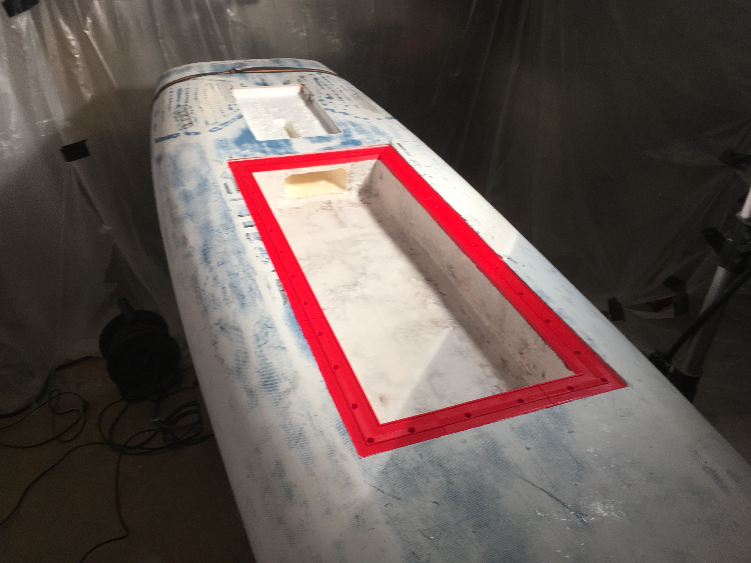
My biggest worry is the box hatch. Really hope it will be water tight. I started to assembly the (red) frame (made up of 8 parts, 4 corners + 4 straights). The corner sections and short straights are epoxied together and curing. Later they will make up 1 frame as per below, but fully coated with epoxy. Finally I will place, from the bottom up, the stainless steel inserts with thread, so I can secure the cover with 30 bolts. In between the frame and cover will are 2 strips of rubber, as a seal.
The big hole is where a 3d printed part (coated with epoxy) will be placed, to route the cables from the box to the mast.
I prepared the e-box first with a layer of epoxy+wood fibres and later with another thin layer of epoxy+filler to make it level. Next, after sanding it smooth, will be a layer of glass.
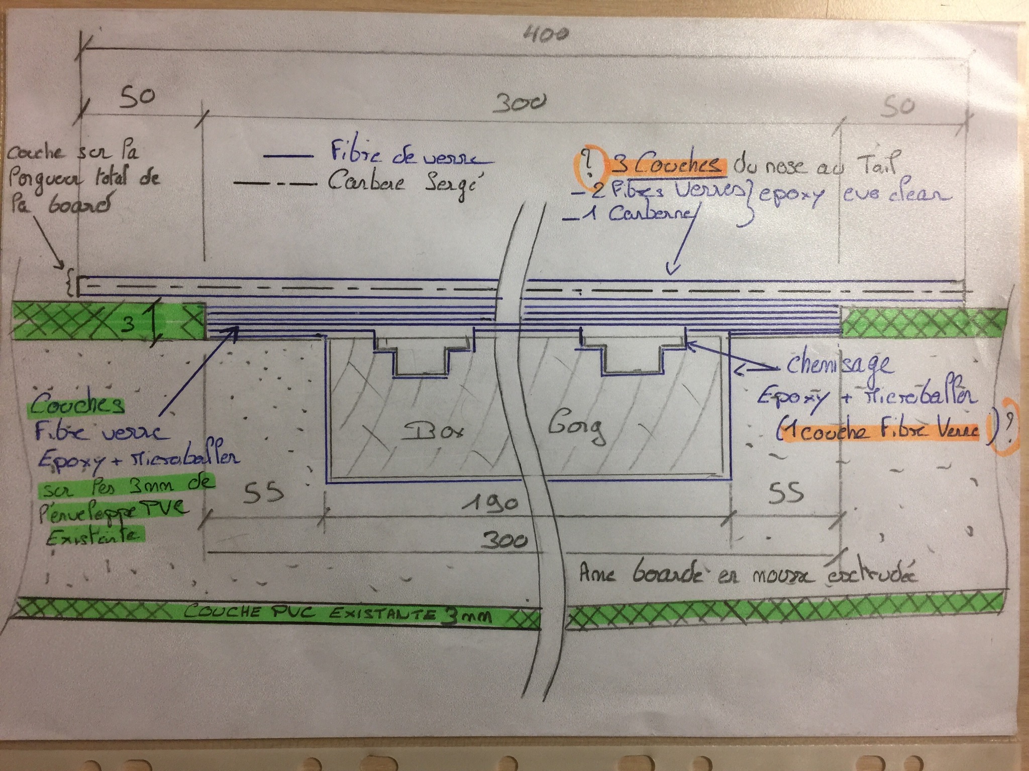
The shallow recess is where a metal counter plate will be placed to give additional strength to the mast connection (see sketch further above).
Looks great. You’ll be surprised how well your hatch seals. Are you using marine plywood for the hatch lid?
hello, the project is advancing, concerning the box for the US rails it is good to make a liner fiberglass epoxy resin micro balloon and then actually several layers of fiberglass resin on the upper part. we can not imagine the force generated by the mast at this place.
Thanks Roger! Good outlook, hope it will work out nice. Yes I am, 5,5mm thickness. WIll epoxy this as well. Did you every had any issues with leaks around the holes of the plywood cover?
Thanks Manu. Trying to follow your proposal. Do you mean to place the liner of fibreglass epoxy resin between the box and the foam of the board? And than additional layers on top of the box, covering the board+fin box, is that what you mean with “resin on upper part”? Thank you.
I agree with you that the loads will be very high, so that why I want to make this as strong as feasible.
I’ve never had more than a few drops get though. I’m still not sure if it came from my water pump or incorrect lid tension.
@Marc87 ,
Thanks Manu, will study this!
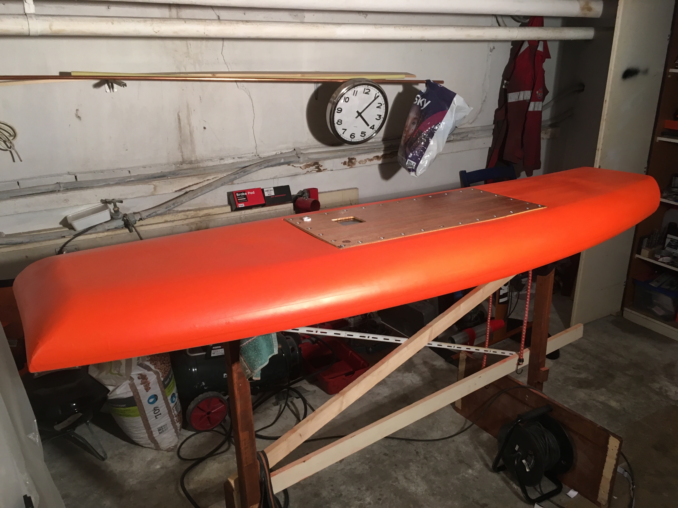
It’s been quite for a while, but I have been working plenty of hours on the project. Especially the board, close to a never ending story of sand paper, epoxy and filler, and again and more. But the last 2 weeks the board took some shape.
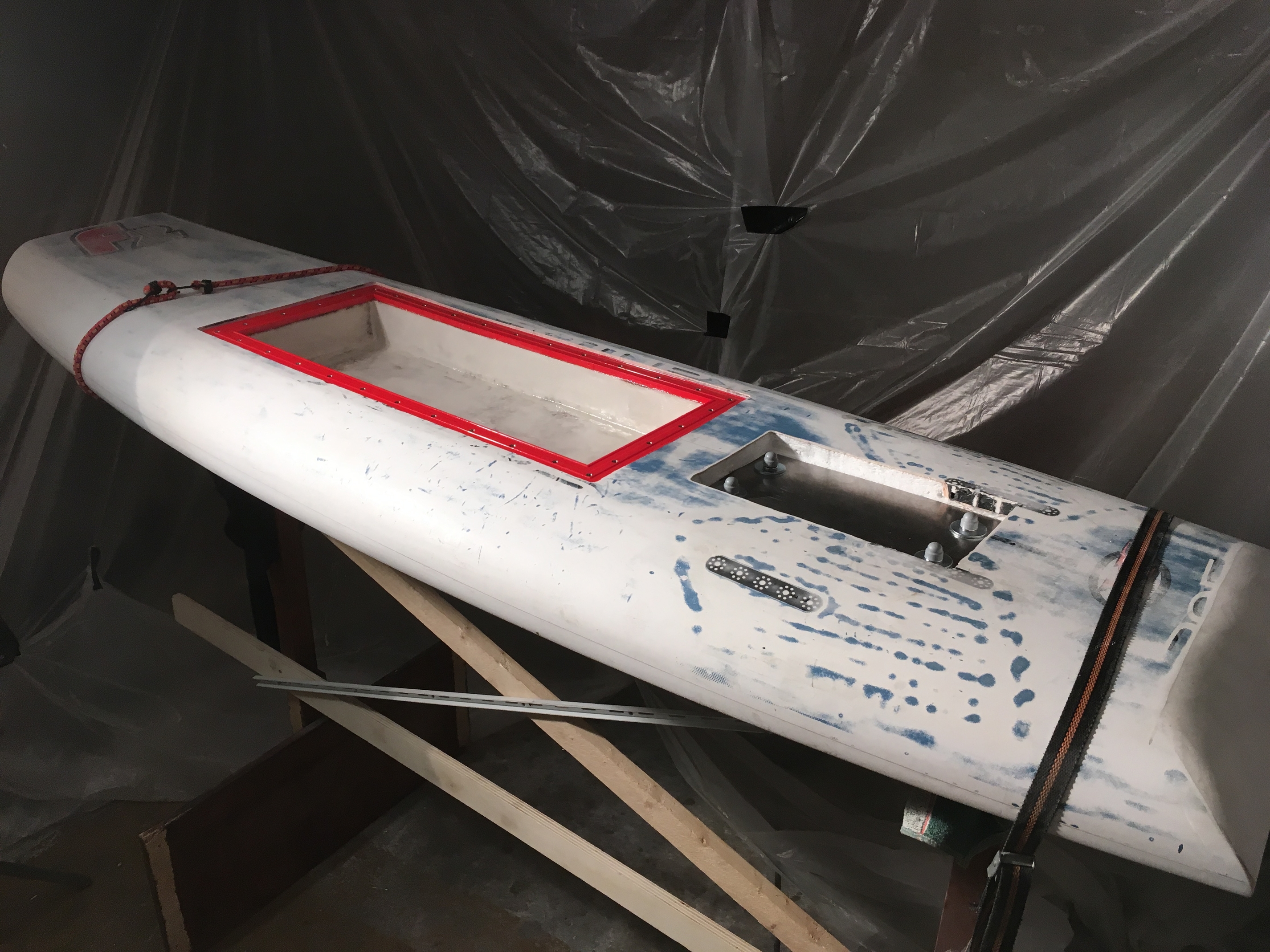
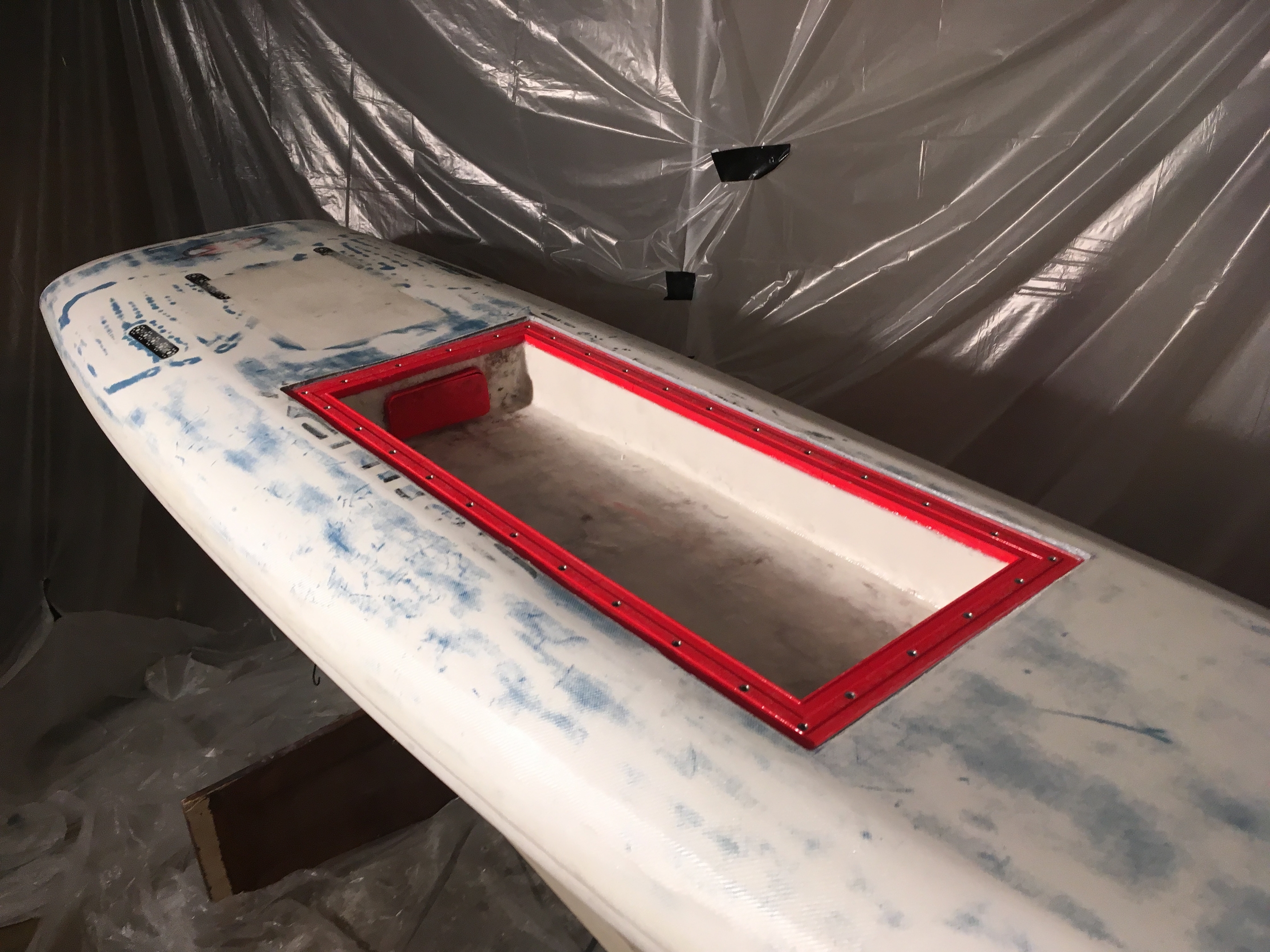
I epoxied my hatch frame into the board, using a mixture of epoxy and a small cotton fibres, to thicken the paste. The wooden hatch was placed on top to create an even pressure on the 3d printed frame. The small gap between the frame and the board was filled with more epoxy. Really hope this is properly water tight.
The steel counter plate with long studs fixed to the fin boxes was also installed and tightened securely. I used metal pipes around the studs between the metal plate and the fin box in order to avoid compression/denting the foam board. It feels quite sturdy. I used a polyurethane foam to fill the hole. So can’t access it anymore.
I left the original glass fibre structure intact wherever I could, but in order to compensate for the Ebox hole I added a layer of fibre glass in the E-box and on the top+bottom of the board. Wooden strips + fibre class were epoxied into the bottom of the board earlier.
Against the backside of the box you see a 3d printed plate+frame. This “collector” is where the motor wires + waterline come from the mast. The collector is epoxied for water tightness and then heavily gloed into the board, to avoid leeks. I will place the cable glands into the red cover plate once the cables are pulled and finally epoxy this into place as well.
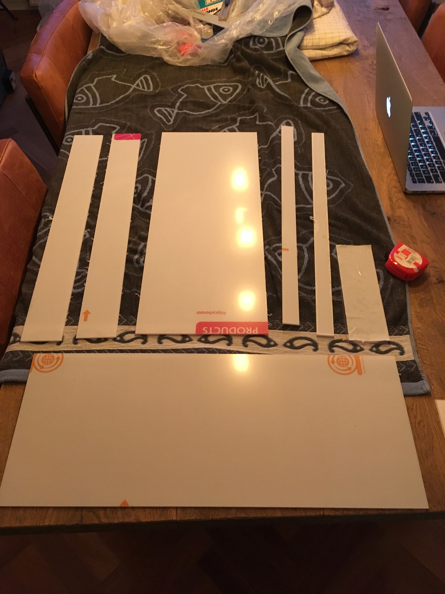
I am quite afraid that the box might not be fully water tight so I designed a polycarbonate box to go inside the box. All the electrics will be installed into the polycarbonate box and some additional cable glands will wire the cables outside this box.
Unfortunately the company did not provide all the parts, so could only glue half the box together.
I guess apart from designing, fabricating parts, overcoming challenges, etc waiting is big part of this project 
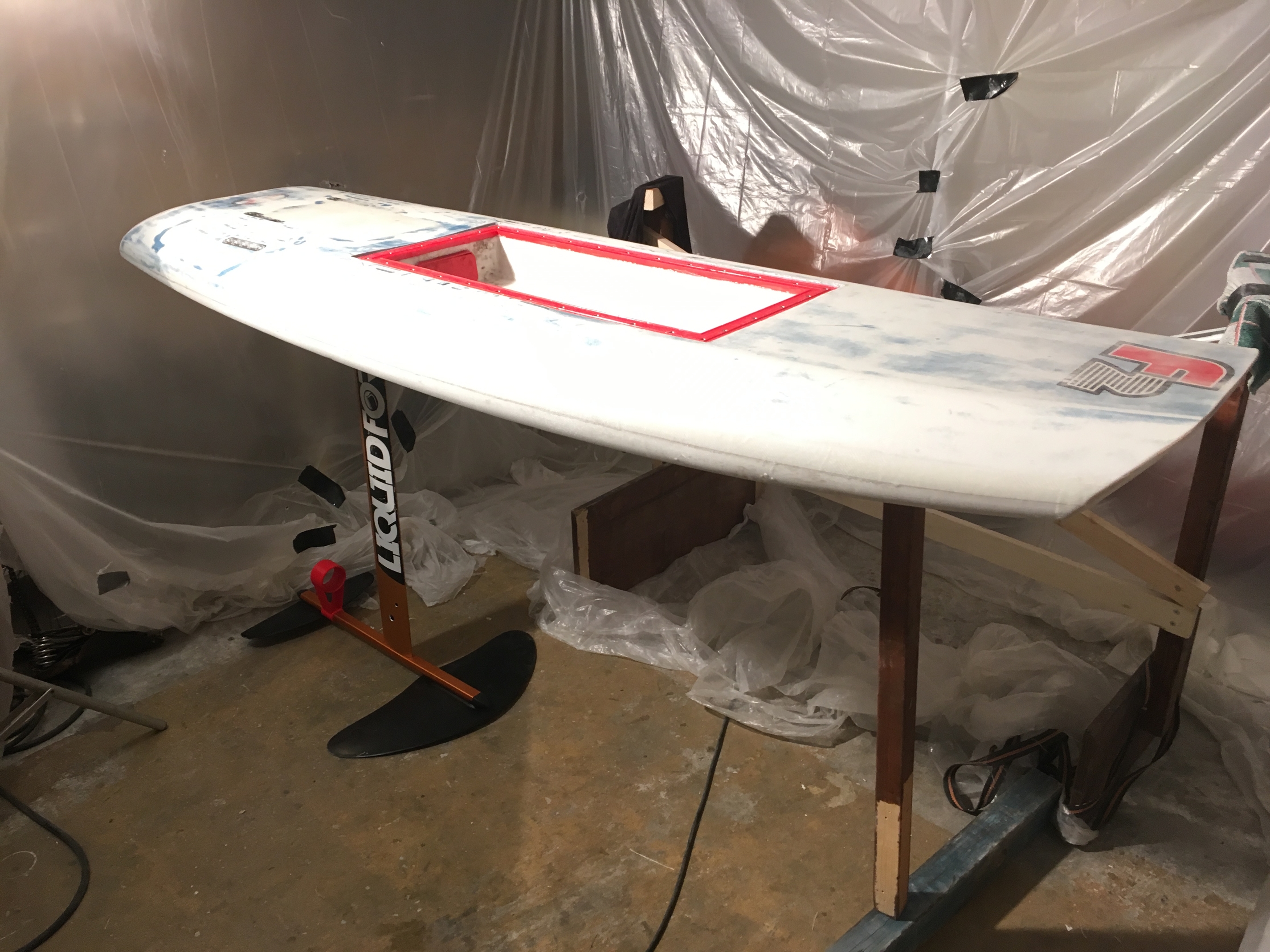
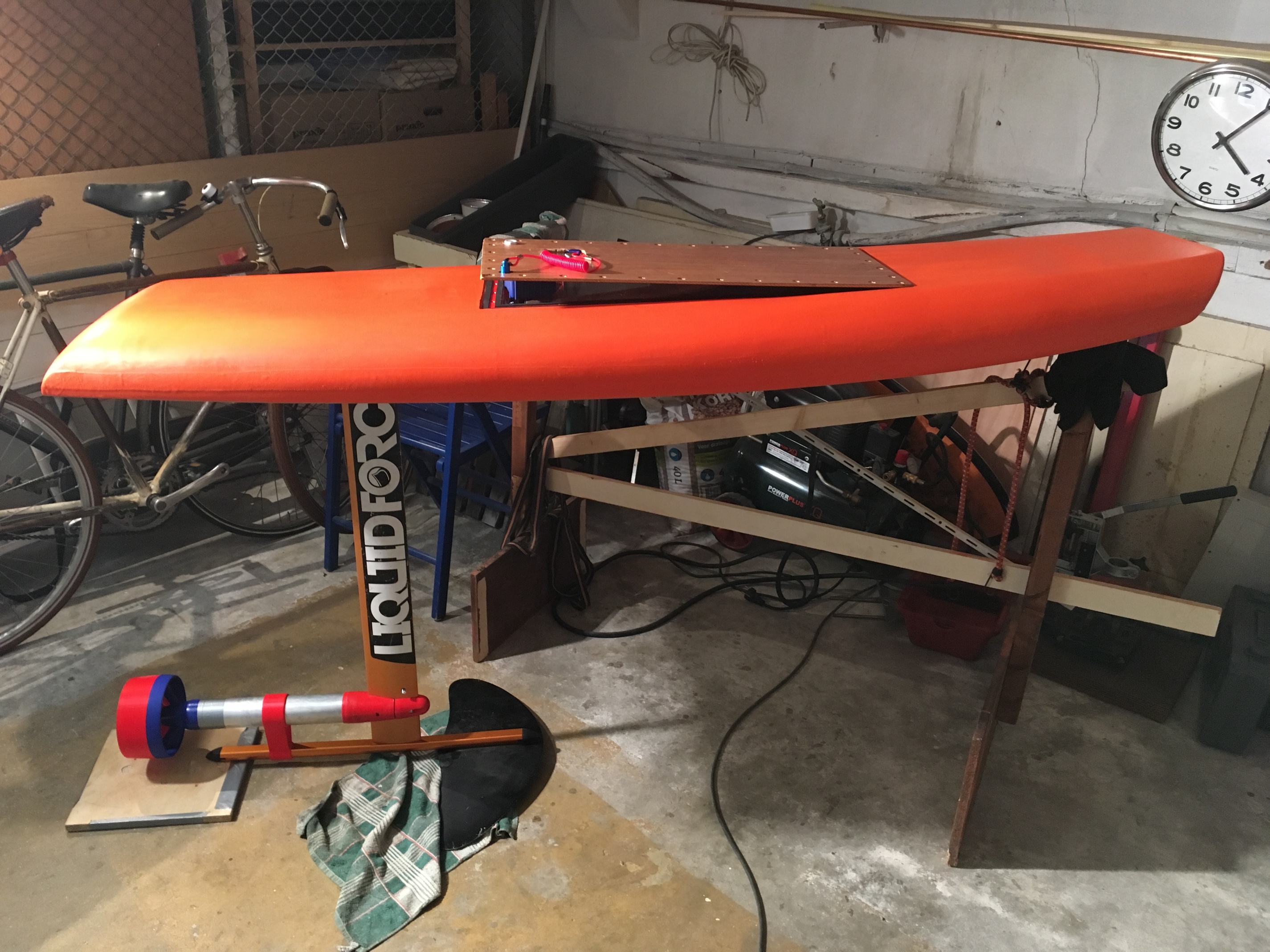
But it is all slowly coming together. Yesterday night if secured the efoil to my custom board for the first time. It does all get quite heavy, have to check the weight, very curious.
Next step is to paint the board. Unfortunately for me 1m above my head here I have neighbours, and poorly insulated floors, who complained about me painting before. So I have to make a paint booth in my guest bedroom.
I soldered all the electrics together and powered the prop with 12S, feels very powerful. So soon I can assemble the motor pod and pull the wires into the board.
Then finalising the poly carbonate box + some other small bits in pieces.
Half May is the target for first testing. Keeping my fingers crossed
I have almost the same shape of board. Mine is only 135cm long and 77cm wide but it works very well. My weight is 73kg.
Cool, sounds promising for me. My weight is about 70 with roughly same volume of the board.
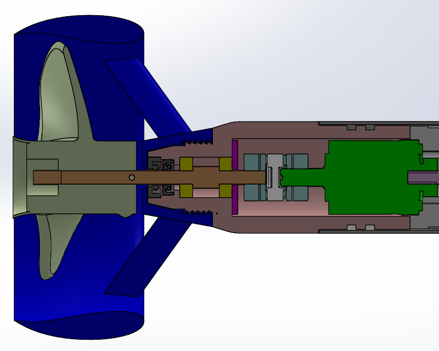
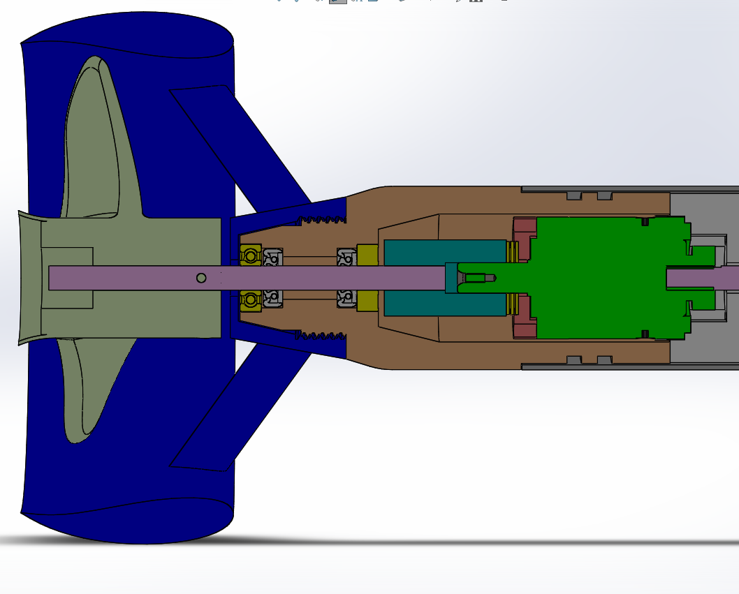
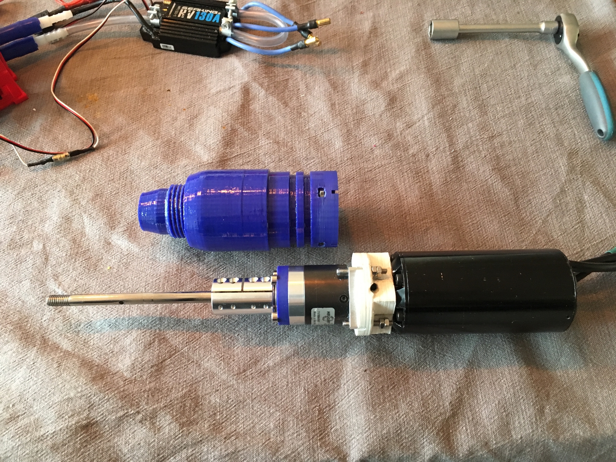
Last couple of weeks I tried to finalize the Propellor pod design. Really afraid that seals will leak because of the mismatch between propshaft and coupler.
Tried a few designs and printed a few new sealmounts to test. Below proposal is based upon a Hiorth setup using jaw type coupler. But I had some issues to make the custom shaft or having it made turned out very expensive.

Today the coupler finally came, and it is quite a unit, 40mm long with two clamping screws per shaft.
So an important moment, would the shaft (by now 130mm) fit properly and will er be less to no wobble during operation. I did not add the second dry bearing yet but what a difference! Below current setup in a nutshell.
I probably will tried the jaw coupler eventually as well, but I’m building for 9months now and want to get onto the water
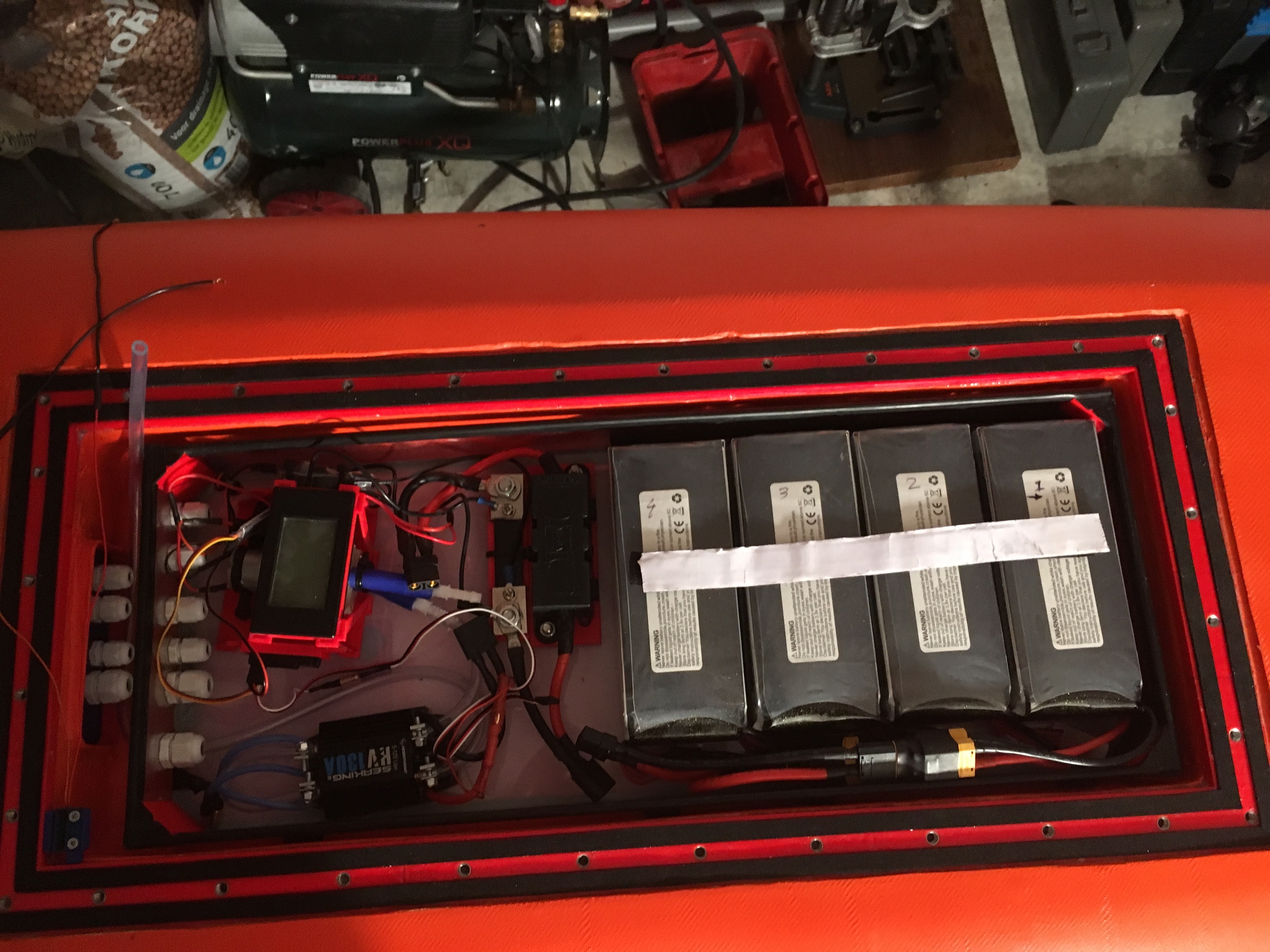
Board and Electric box are pretty much finished. Just need final positioning of the ESC and pump/display mount.
The E-box is a box in a box. So a bit weird, but have 2 lines of glands to get cables into the board. Water tightness test 1 was positive and increased it a bit further with the rubber seals ontop of the box (visible below).
The batteries a secured with Velcro and this seems to work very nicely. A rubber strip is mounted to the inner polycarbonate box side walls. So hope the lid seals even better now.
I plan to assemble the Prop pod this weekend and pull the wires in. Lets see how it goes.
Congrats on the build, looks good. Your big coupler looks similir to mine, Ruland stainless, quite big. Mine has a slot for a key which prevents slip (a common problem when using a coupler). Due to the lenght of the coupler, the shaft alligns quite well, 5/100 untrue at the pod exit of the shaft in my case. I don‘t know how much wobble other builders have, would be interresting to see if you have a dial gauge.The coupler should be balanced to reduce vibration. I removed matrrial with an angle grinder until it was balanced.
Thanks @sat_be Daniel. I have a non branded one, but think will work same as yours. I haven’t measured the untrue value for my setup, as I don’t have a dial gauge. Might ask around if somebody has this laying around. Eye balling it so far and looks promising. Leaks at the seals are one of my big worries.
Good point regarding the balancing, will check it out. How did you test this?
Put a shaft through it and put it on 2 parallel bars (shaft on the bars, coupler in the air). It will turn to the position with the heavyest point to the down side. (The side opposite of the screws). Mark it and remove some material with an angle grinder. Repeat until it keeps the position. You can also see it in the way it mooves when you create a (very flat) slope with the parallel bars and let it roll down. Only remove small portions, don‘t remove too much.
Thanks Daniel, very clear. I actually read about it for RC props, logical to use it for this purpose as well. Going to try it out.
Worked the whole weekend to finalise the board. I think i am sort of there
I pulled the motor wires + water cooling line into the board and secured the mast to the board.
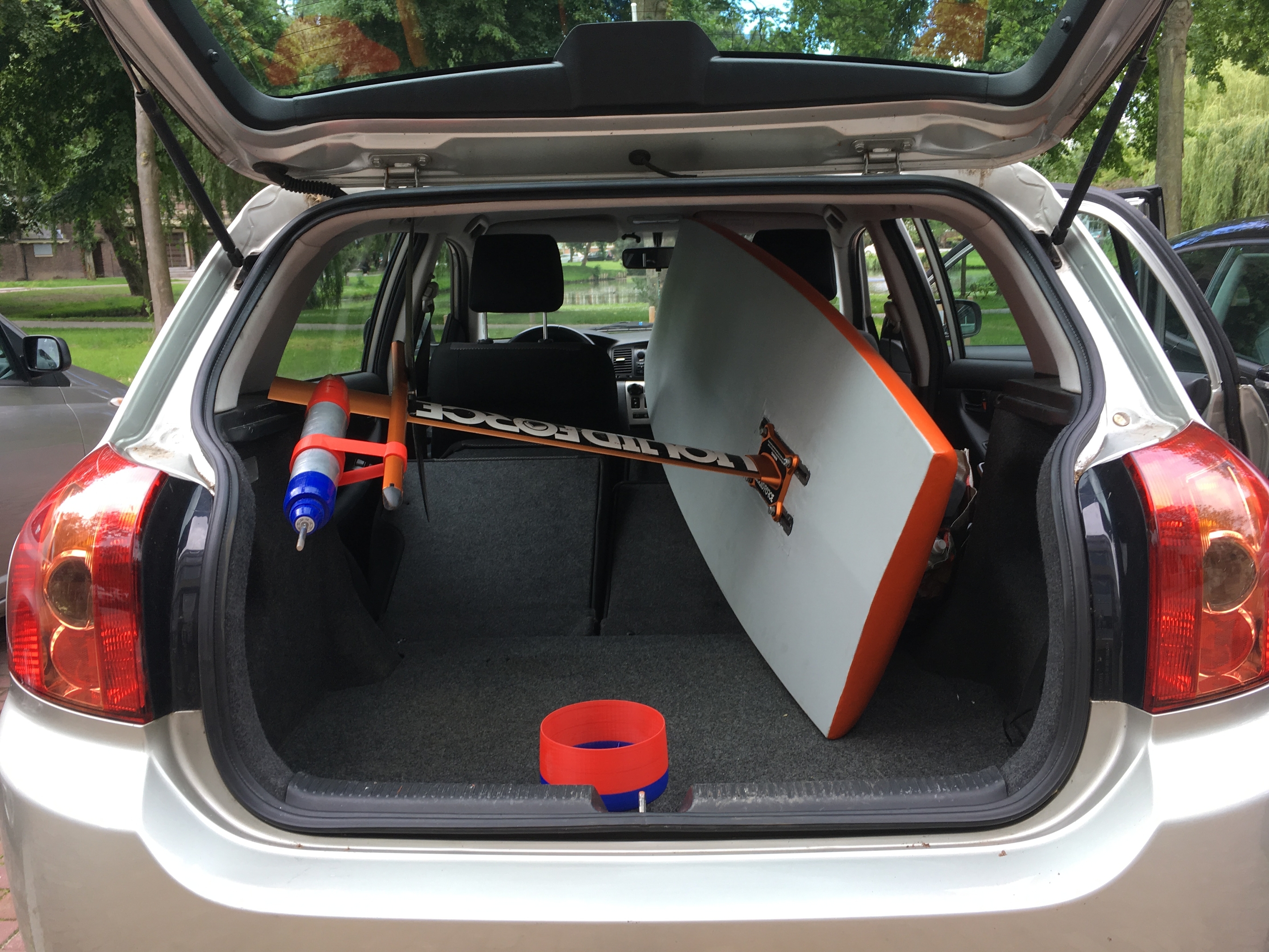
It actually fits in the car, only requires to disconnect the fuselage + prop&duct.
Up next was to hook up all the wires in the E-box. Quite a bit of work and I hope my soldering holds up. Working half standing with clamp and soldering iron over the box was a bit tricky.
Tested the motor a lot and it works great so far. The dead-mans switch also works good in dry condition and “loosing connection” with the remote also switched of the motor. I hope its ready
What’s left is grease the seals of the wooden lid, securing the rear foil and getting a wet suit. The batteries are all charged up. And so am I. I feel very excited and a little anxious as well. Hope it doesn’t go up in smoke!
Next: actually going into the water, hope I can bring some positive news
Water “shoes” and suit , help for the knees the first time ( getting on and on the board a few time …)
Yes, the water shoes also. I have those from wind surfing. Did you also added the “grip” on the board itself (don’t know what it is called)?
Good tip, will try it out like that

