@Winging_it
Hi Dan,
I very much enjoyed your work with the flume and your detailed explanations and results, thank you!
As I’m interested in also building a flume (while I don’t know, if it will come to happen) I have questions about some points. It looks like you have used a long propeller shaft situated in a long tube that is fixed at the flume. In order to measure the thrust, the shaft must be able to move a bit in axial direction. Therefore it is not appropriate to use ordinary bearings to bear the shaft. You will have used some lubrication between shaft and tube to prevent water from outpouring, right? If so: was it water, oil, grease other stuff? Did you use seals or other means to prevent leaking? What were OD of shaft and ID of tube?
I don’t know how Winging_it did it. This is how I did it.
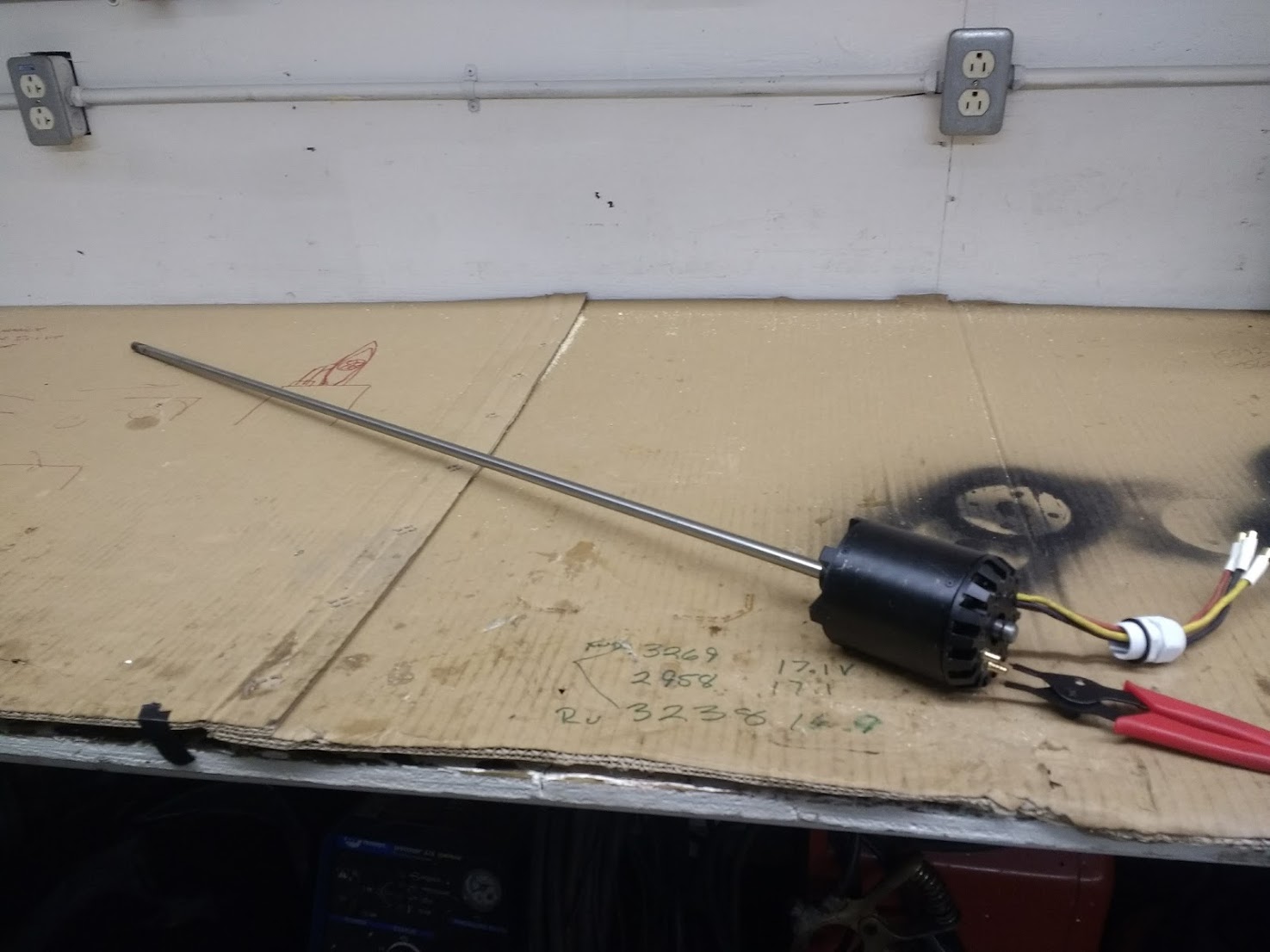
I replaced the shaft that came with the motor with a shaft about 3 1/2 foot long. 12 mm shaft.
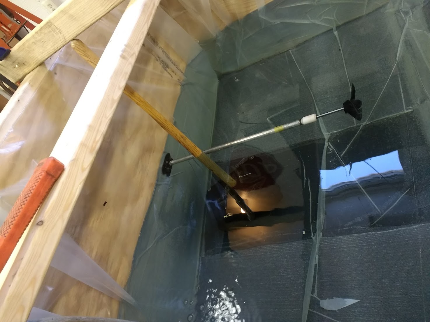
I printed a part in white plastic that held a needle bearing cage with needle bearings. I think I bought it from McMaster carr. I also installed a seal in the white printed piece to keep the water out. That white piece threaded on to 1/2 NPT pipe. On the outside of the tank you can see that the motor shaft passes through a brass colored part. That is just a brass adapter to go from NPT thread to a flair. I opened it up to 12 mm and I am using it as a bearing to keep the motor centered. It worked very well did not leak a drop for months. The tank was 6 foot x 8 foot x 4 foot deep. It also took up so much room I had to disassemble it.
The shaft bearing was a simple nylon sleeve type. It allowed the shaft to slide and did a pretty god job sealing the water. I think I used a little bit of petroleum jelly as a lubricant and sealing media for the shaft bearing/seal.
I believe the shaft was 12mm in diameter to match the motor shaft. I don’t recall the ID of the tube, but I think it was about 1/2 and then I drilled it to accommodate the nylon shaft seal/bearing.
If I were to build another flume, I would add another motor and prop to help get the water moving faster in the flume’s test section. I had a boat speedometer in the test section of the flume but it never read more than about 5 mph. I think testing at cruising speed is really important for getting a god motor/prop combination. Just putting a propeller in a big water box will not do a good job measuring the prop performance at speed in an “unloaded” condition.
Dreaming on a larger scale, wouldn’t it be great to have a powered flume large enough to allow testing of complete hydrofoils/efoils in addition to the power systems. This could really help in the refining, performance and duration of an electric hydrofoil.
Thank you. I mostly built it because I really had absolutely no experience with these high performance motors. I never even heard of a out-runner. I never hear of a Flume either. I wanted a way to run the motor hard and monitor everything. I wanted to make sure that when summer came I had something that would not burn up. If your motor does not over heat in your flume tank it probably never will because the motor is fighting against still water rather than the fast moving water it will see in the real world application.
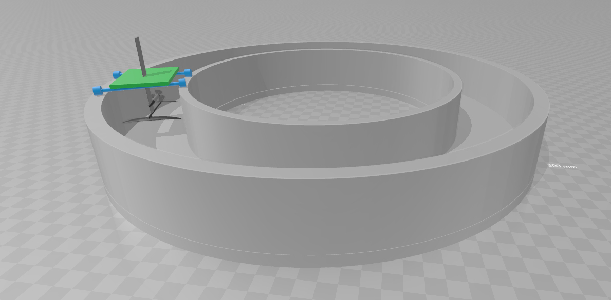
I always thought u 2 would make flume v2.0 for futher testing and i always thought it would look something like this Could this actually work? Weight scale (for lift) esc batteries etc on top of thiis green crap (which should be heavier than rider and board weight), anchored in the center (which i forgot to put in) to circle around? Maybe 1 or 2 motors iin the canal to simulate “flying speeds” but this is awful lot of water volume. Maybe a gas outboard?
That would work. I was thinking the same thing about using an outboard motor to power the water in the flume.
A few things I would do differently from what you have shown (if I had a place to build a flume #2) are:
straight section of flume for the test section
Widen the test section. If the wing tips are too close to the walls, induced drag will be greatly understated.
Instead of the cart you have shown, I would use a long horizontal pivot arm attached to the top of the mast and anchored in front of the foil. I would add weight = to the flying weight to the top of the mast. This way lift is aways = total weight lifted by the foil, drag is the pull on the arm (efoil power off), power required for flight at any particular speed determined when pull on pivot arm is zero.
You mentioned, but not shown in your drawing, an independent motor/prop to power the water in the flume and control water speed.
I don’t have cad drawing resources available. Would love to see someone do a nice rendering of some good ideas for a really good flume.
Wouldn’t it be great to have a good flume to test and compare existing efoils?
Oh this was just a principle, took me way less time to sketch it than to translate to english how i would want to describe it. If i get some free time, will try to model something. And yes, a proper flume would be wonderful!
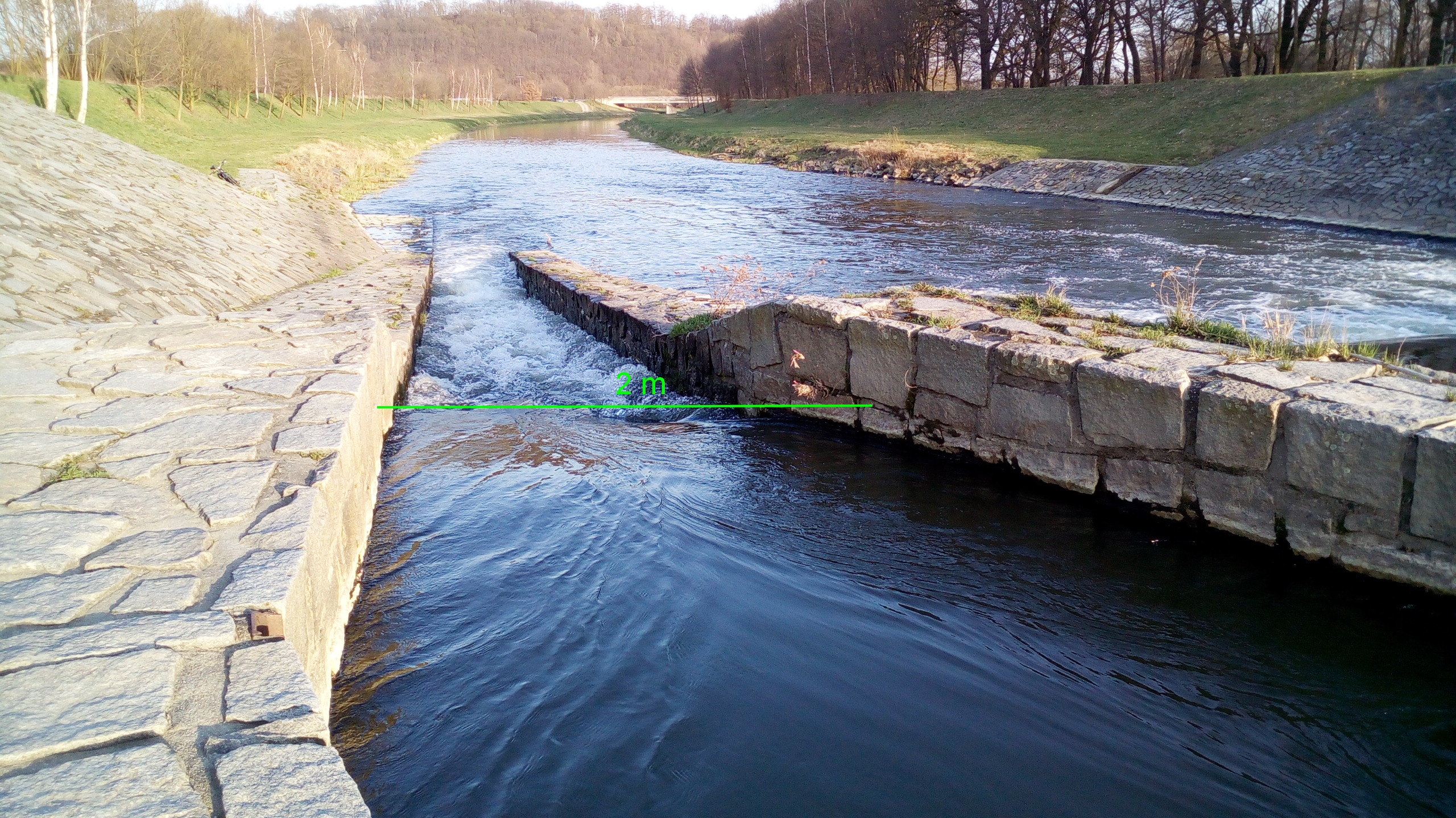
Depth 1 m, width 2 m, I don’t know the speed of the current, I have to measure. At this point it will be possible to measure the efficiency of the propeller and wing very accurately. The most important thing about a propeller is to measure thrust - g / W. I use a portable professional device for measurement.
Hi @Dynamik, This is fantastic plan. Thanks for sharing!. What props are you going to test? Please keep us updated. Efficiently is most difficult thing to achieve.
Here I will only post a few more photos when I am on the water canyon. But I must first make a detachable 2.4 m aluminum frame, which I will lay on both dams (similar to the picture from Just - see above).
I must first calculate the correct propeller shape for e-foil. But the propeller parameters (efficiency, thrust g / w) and its 3D CAD will be published in a different topic that is more appropriate.
How to calculate the torque required to get the prop RPM and thrust required?
I am building a double jet drive with 50mm props using 790kv motors in direct drive, and I am not sure the torque will be enough to hit the RPMs required at the shaft. Using a 12s6p 21700 li-ion battery pack rated at 4.2a/cell, 43.2v. The motor outputs 7.77kw of power at 12s and 180a max amp rating.
I calculate that at 55a draw I get a HP of 6.4lb/ft and need to spin the 50mm prop at 10k RPMs to get a 259N force (58.3lbs). With direct drive, what torque do I get and is it enough using the 790kv SSS motors? Or do I need to reduce gears 2:1 or more?
short answer: yes if your motor is 56mm type it will have enough torque (2.5-3nm) to spin a 50mm jet drive to 10krpm
long answer: 10k is not much for this size, i haven’t built a jet surf myself but i have done some work, and i would aim for twin 50-56mm jet drive with a 25k rpm off load (-30% on load)
taking a 43.2v battery would give (25000/43.2)= 500-600kv motor
if we want 10k rpm so about 13krpm off load using a 790kv , you will drive this motor only at 16v, taking your 55A (from the battery is suppose at 43.2?) 55ax43.2v= 2376w , this 2376w/16v= 148A on the motor , yes it will take it but overheat
2:1 or 3:1 gear would work , but addding complexity to the built, to me the best would be to get a ±360kv motor 56114 or 56123 type
match kv motor to the desired rpm according to the battery voltage
it is pretty hard to convert mecanical power , torque , thrust, heat loose…
Not sure I understand the 16v. I thought voltage is constant at 43.2v, and loaded at a 2376w that would imply the motor is drawing 55a.
I thought about the 56114 or 56123 but as it is the 56104 is rated for 11kw and I figured that at 790kv I’d only be tapping into 70% of the power, as 43.2v*180a max draw is only 7776w. But I am not exactly 100% sure how this all ties together, it’s like a splinter in my mind, driving me mad, not being able to see the whole picture. Also costwise, the 104 are $100 around and the 123s are twice as much. What is the benefit I am not seeing here?
So here’s what I got so far:
case 1
The max HP at 70% of max W for dual jet drive is 20.86 ft/lbs/s. With a motor RPM of 34,000 (79043.2) in direct drive, that gives a total torque of 3.21 lb/ft (T= (5252 * HP) /RPM or 4.35nm. At max amps of 180, total wattage between the 2 motors is 15.5kw. Loaded RPM as you put it would be 23.8k (34k0.70). Given a displacement of 204.05lbs, KTS would be 72, or 83mph. With cavitation starting at 36mph, max thrust of 380N, a prop of 41mm, and pitch of 79mm, pitch ratio of 1.91. 2 bladed props.
case1b:
same as above but dropping gear 2:1, shaft RPM would be half 17k, torque doubles to 6.42 lb/ft, prop diam is now around 50mm, and pitch 124mm, pitch ratio 2.56. Cavitation starts at 55mph now. I could push cavitation to 69mph if I had a 4 bladed prop instead of 2 with the increased blade area.
Case 2
Changing to 360kv, max amp is 95, 43.2v.
The max HP at 70% of max W for dual jet drive is 11 ft/lbs/s. With a motor RPM of 15k (36043.2) in direct drive, that gives a total torque of 3.72 lb/ft (T= (5252 * HP) /RPM or 5nm. At max amps of 95, total wattage between the 2 motors is 8.2kw. Loaded RPM would be 10.5k (15k0.70). Given a displacement of 204.05lbs, KTS would be 52.3, or 60.2mph. With cavitation starting at 39mph, max thrust of 270N, a prop of 58mm, and pitch of 127mm, pitch ratio of 2.2. 2 bladed props. Taping only into 37% of top wattage the motors are rated for, leaving a lot on the table by the looks of the math.
The jet drive looks so powerful already. It’s a 790kv motor 50mm jet at 6s
Anyway, I am thinking I definitely don’t want to go above 50mm, as my surfboards thickness is about 3in, so the 50mm jet drives would be nicely flush. The 2:1 poses some complexity. The planetary series gears don’t seem to handle more than 7k RPMs so that seems out of the question. Someone in another post posted an interesting gear reduction motor mount that would be quite minimal, but could not find much about it, and works with a belt.
Ideally I’d just use the 790kv motors. In my limited understanding, the 360kv look like would leave a lot of HP on the table as its capped at 95a.
I could drop the volts down to 6s for 790kv motors for a max rpm of 15-17k or increase V to hit that 25k RPM you suggest.
How did you figure 25k is a good RPM for 50mm twin jet drive?
dc volatge on battery 12s goes from 50.4v to 38.4v
controlleur will convert dc current to wave Voltage for the motor
the motor will see the voltage by peaks at a frequency
by the thorttle you change the switch frequency so the time the motor sees the peak voltage (of the battery)
so with a 790kv on a 12s fully charged 50.4v, to get 10000rpm , it is about 25% duty, 25% at 50.4v and 75% at zero : average 12.6v
if you convert thrust into mecanical power you need take this in account, the impeller will draw the amp needed from the motor to spin at the desired rpm, the motor will always give to a point where the rpm will drop
25krpm : just reading and seeing other jet board setup, mhz data on 52mm…
aiming for this rpm off load , included heat and mecanical looses, and voltage drop on battery and voltage sag of cells, to end up with a constant 15k rpm at least
reisanauer planetary gearbox take 50krpm , no problem
Edit : my Calculation were made with impeller with a ratio closer to 1-1.2 , so with your high pitch I don’t know , but for sure the best is to keep the highest voltage possible for the motor so the lowest kv : to match the best rpm of the impeller
I have some more reading to do now. Any highly recommended link suggestions to read so I can understand this better? I usually find some gems articles or forum posts but it can be luck.
Can only seem to find 3:1 and up for that gear. That’s some RPM claim
Yes the pitch is just too high, based on this calculation from this book Propeller Handbook. I would ideally want a variable pitch like in Jetski propeller with lower pitch at the leading edge and higher at the trailing edge. Do you know of any 50mm prop with variable pitch?
I am not sure what the best RPM of this 50mm prop I show on that video link above. The seller suggest 6-8s on it with a 500-790kv, so I may end up just copying it. Making a 6s12p pack or more. The costs are a lot lower with higher kv motors it seems, just would need to have more parallel cells to have higher amp pack. I read somewhere the torque between low kv and high kv motors is the same as long as the other factors are suitable like high voltage for the former and high amp for the latter. The battery life is about the same considering 12s6p or 6s12p is about the same # of cells and total energy in Wh
I was thinking I can make 6 packs of 2s6p and then I can connect them in series or parallels in many combinations to suit my needs and try different voltage/amps. I can make 2s36p, 4s18p, 6s12p, 8s6p, 10s6p, 12s6p. Most of those combos are not practical for this but I guess it’s nice to have for other projects.
Using the 6s…
Based on that book, the min diameter the prop should have for a board with a beam of 2ft and “hull” draft of 1.5in,which is the dimensions of my surfboard, it is exactly 2.04in (51.8mm).
Rounding down to 50mm, or 1.968in. The calculation for the shaft RPM given SHP (HP0.96)for the motor of 5 SHP (790kv at 180a 6s), it is exactly 25,022RPM (((632.75^0.2)/1.968)^1.666). This may be the best rpm for this prop according to that book. But the book is mostly about screw props and not about jet props.
Then to get the MPH it is KTS =(1-10%)*230/(204.05/10.01)^0.5 the KTS is 45.85, in MPH it is 52.
10%slip
230 constant for high speed craft
204.5displacement (my weight including board and equipment)
10.01 the SHP of the 2 motors
I will try to put some links this we
For the motor it is about right , you look end up with the same torque using different kv
For the battery not the same , its discharge capacity is not linear, the more you pull from it the less you will get ( heat)
Several 2p pack is not the best solution , you will need multiple bus bar and big wires to handle the amp , may be go with 4p : 8s then 12s
Some reading :
Here on the forum , you have multiple Efoil setup with data logging via vesc and metr : you have the values : rpm, battery voltage and current , duty , motor current to understand more about all this
I may just copy his build. From what I gather, he’s running dual jet drives 53mm with 500kv 56123 SSS motors, 400a ESC, 8ft foamie, not sure what voltage he’s running it at. Maybe 10-12s?
He’s going so fast it seems, exactly what I want.
He burnt 2 motors in his pt2 video. He said maybe because he ran it at 12s. But also his motor KV was 700 around. So that combination didn’t work.
He may be running the 123s at 10s.
It seems like you were on point with the 123s earlier. You can get the lower heat from them and won’t burn up as easily. Also, higher loaded RPM right?
Would love to see some data logging from people. Still looking but haven’t found anything. Not sure what search term to use to find that
One concern I am having is the Chinese 50mm jets, while cheap may proove weak with high RPM of 20k
 Could this actually work? Weight scale (for lift) esc batteries etc on top of thiis green crap (which should be heavier than rider and board weight), anchored in the center (which i forgot to put in) to circle around? Maybe 1 or 2 motors iin the canal to simulate “flying speeds” but this is awful lot of water volume. Maybe a gas outboard?