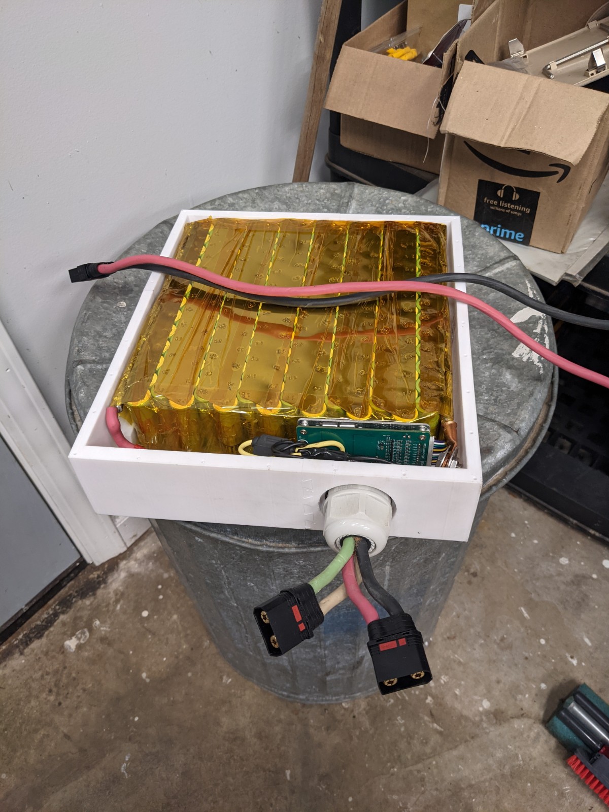
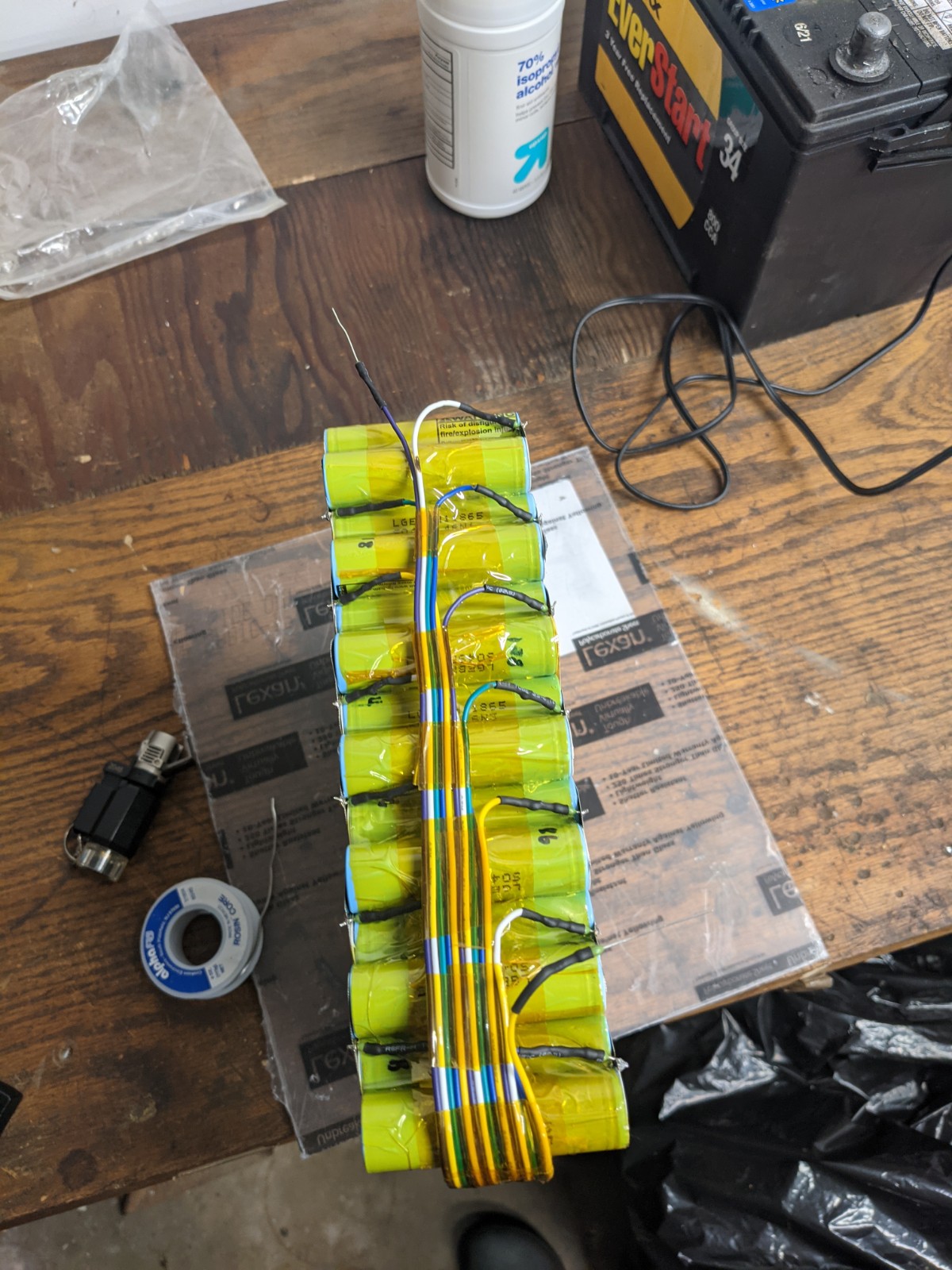
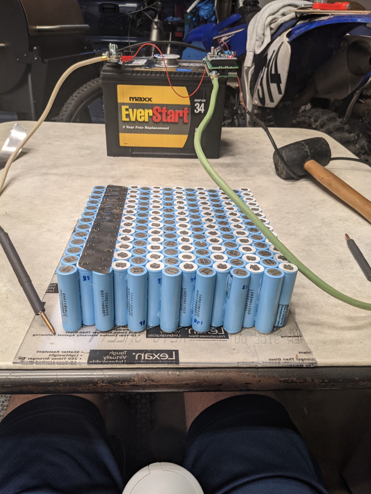
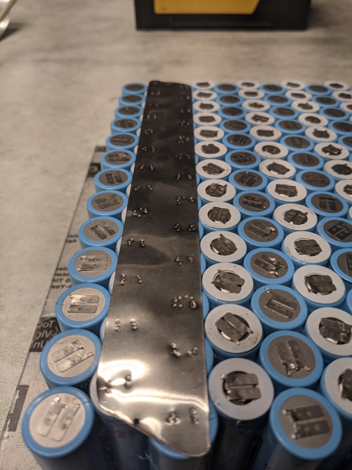
Nothing is worth the shot is Efoil world , just safety and quality work to get away of trouble , get a decent spot welder , make the battery and sell it if you went to save some money , don’t forget we are talking about more than 600 spot weld for a this king of battery  for me that was sweating and letting my fingers cool down
So I have been thinking about this for 2 weeks but cannot decide on the best design. The goal is a detachable mast design. So initially I was thinking female plugs on the bottom of the board that the mast plugs into. But I’m not sure if that’s the best. Looking for advice. I want it to be easy to remove mast for transport.
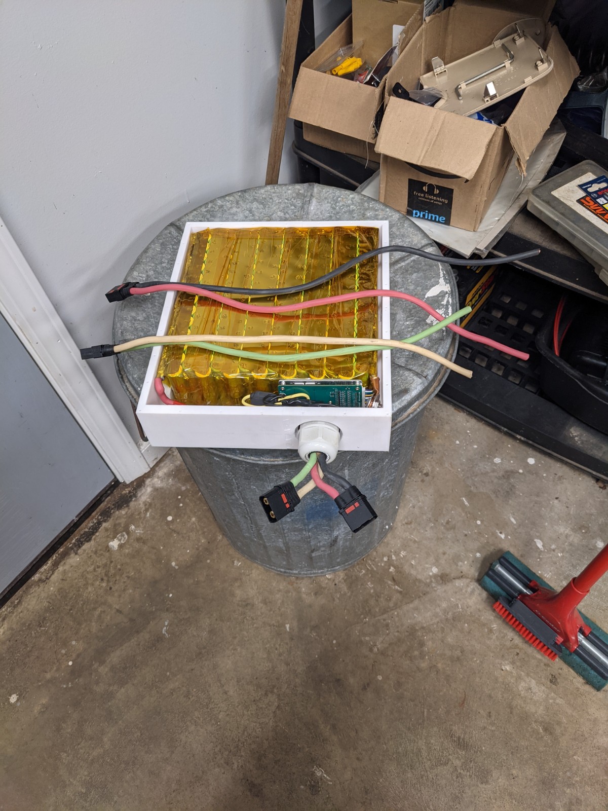
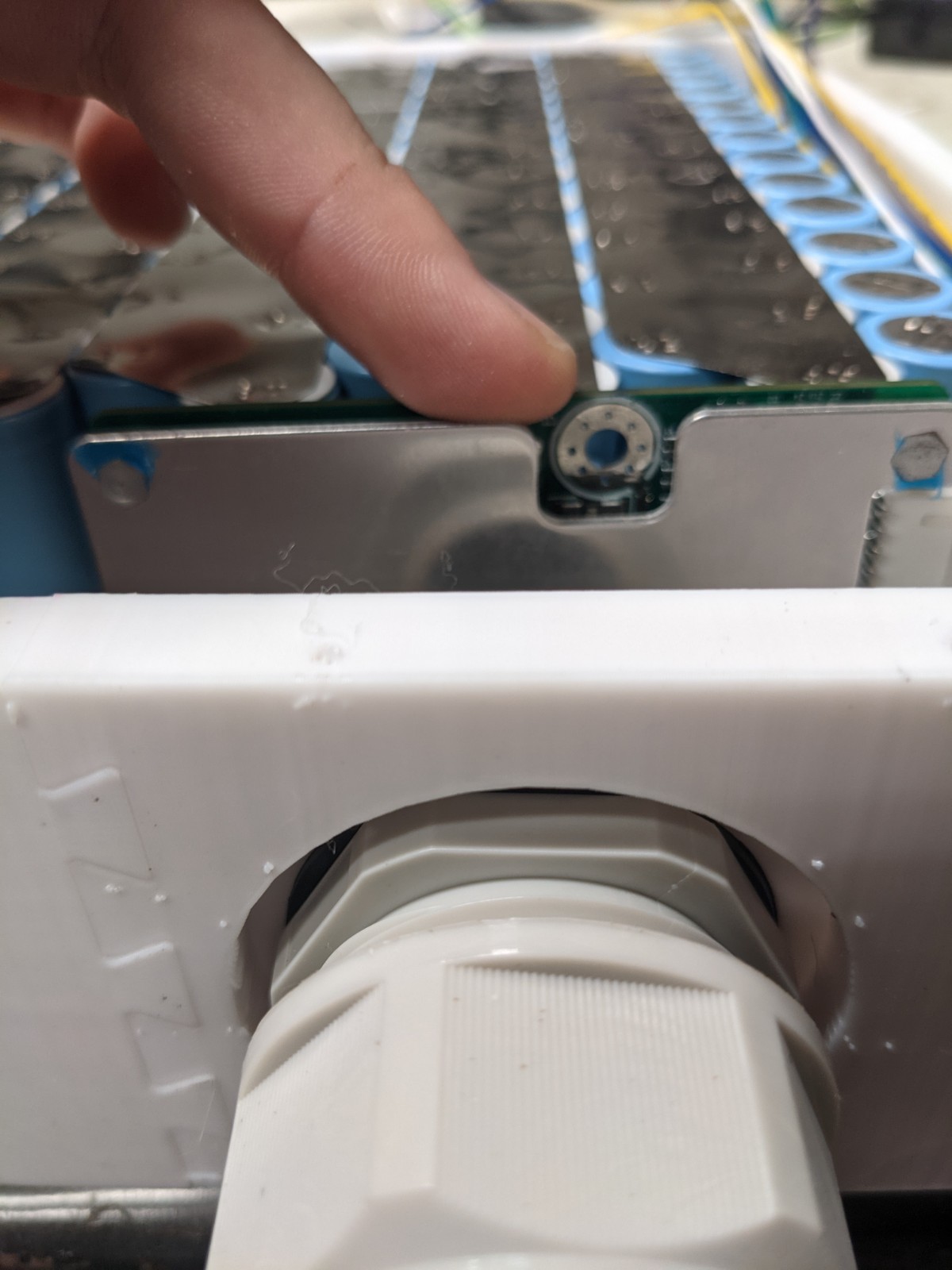
I’m planning to try putting an aluminum plate on the bottom of my board where I attach the foil, and then cut a slot for the 3 motor cables to pass through. Inside the board I’m using 2 IP67 boxes with grommets and in-line connectors between the battery & motor boxes and between the motor and the ESC box. The connectors are MUCH cheaper that way, should still be very water resistant if water gets in the board, and should still keep water out of the board.
2 Likes
That’s a good idea however I’m not sure how that makes the mast detachable. Do you plan on making the slot big enough in the plate so the IP67 connectors can fit through? Or can the outer shell of the connector somehow be removed so you can pass the motor wired through the slot?
My bad, that wasn’t clear. I was planning on making the slot large enough to fit the connector through. Then it should be fairly easy to take out the 4 bolts on the mast and pull the cables & connectors out. They’re less than 1" O.D. so it shouldn’t be hard.
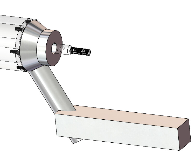
Hi, we both have a common goal. I can’t show a picture yet though, maybe early July, I might be able to make it. However, I have the quick release system very carefully thought out, but all I can tell you now is that the connection to the mast will be made by two long screws (possibly titanium).
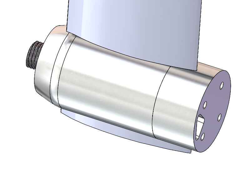
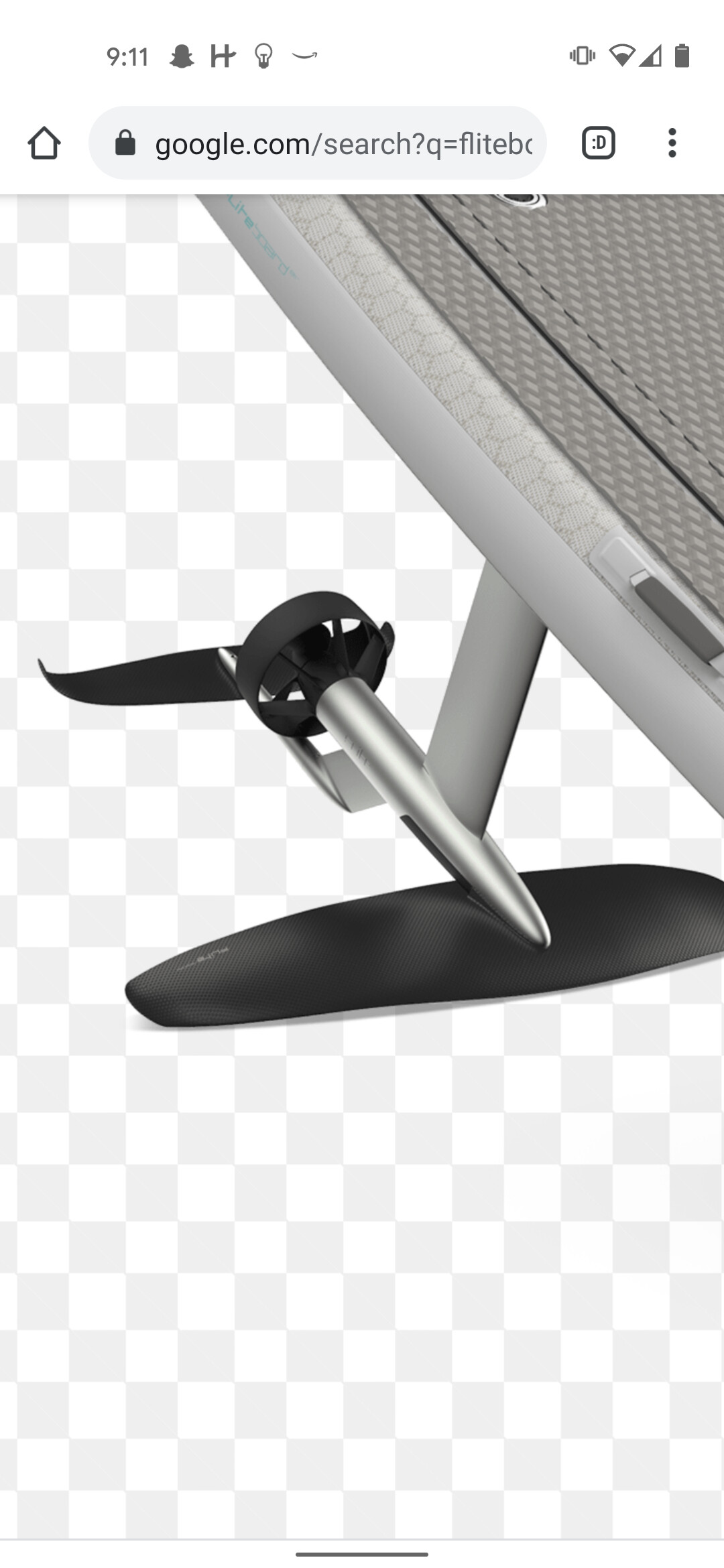
Unfortunately, our goals diverge in other respects. I have started an e-foil project based on the Fliteboard hull design(https://cdn.motor1.com/images/mgl/1M9bK/s1/fliteboard.jpg). The Fliteboard e-foil is considered the best in the world. Placing the motor in the plane of the wing is ideal from a hydrodynamic point of view and brings a number of other design advantages. This is my fuselage design
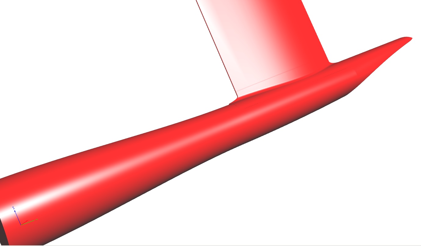
(the actual color will be red with a very high gloss, like the Ferrari color)
2 Likes
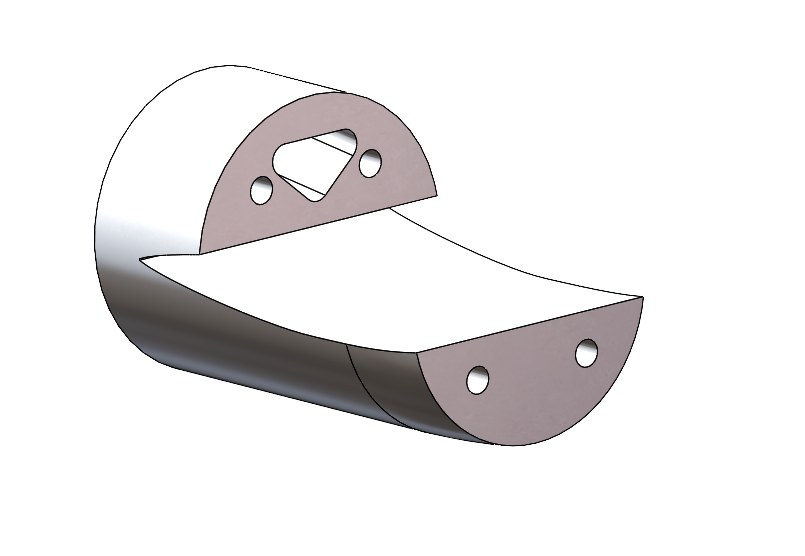
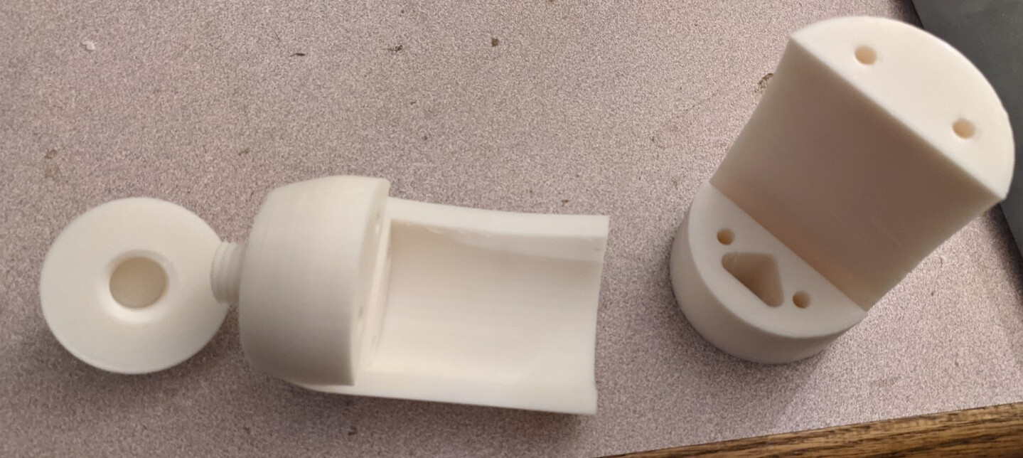
Did some work on the mast clamp design. Inspired by @nice2cu and @manu clamp designs. Have not loaded them into the printer yet. Also nose cone not finalized. Designed for gong mast V1. The reason for large cavity is because I want to run wires up both channels inside the mast. Not just one side. This way I can access both channels inside the mast.
Question to my USA friends, where are you getting your super long (135mm+) M5 bolts from? Are threaded rods being used?
1 Like
Update to my own question:
I am going to use threaded rods and these cool adapters I found from belmetric. My friend is a stainless steel welder, I envision screwing this on the whole way and welding it to the threaded rod.
McMaster has what you want.
I like the stainless steel 110mm m5. You can go up to 140mm m5 in black oxide.
Mcmaster is my favorite.
I want to run in saltwater, so I do not think black oxide would be best.
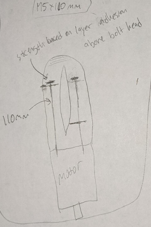
Unfortunately if I use 110mm hardware, I would not be able to use the mast clamp I want to use shown below. The smaller hardware limits how large I can make the “pocket” to route the wires inside this mast clamp.
I also want the hardware to clamp all the printed layers together. In this way the layers are being held by the clamping force of the hardware and not just layer adhesion. I think this will benefit the strength of the clamp greatly.
Here are some comparison sketches to see what I mean about clamping all the layers.
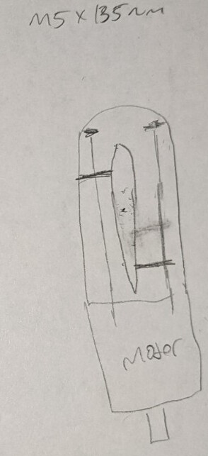
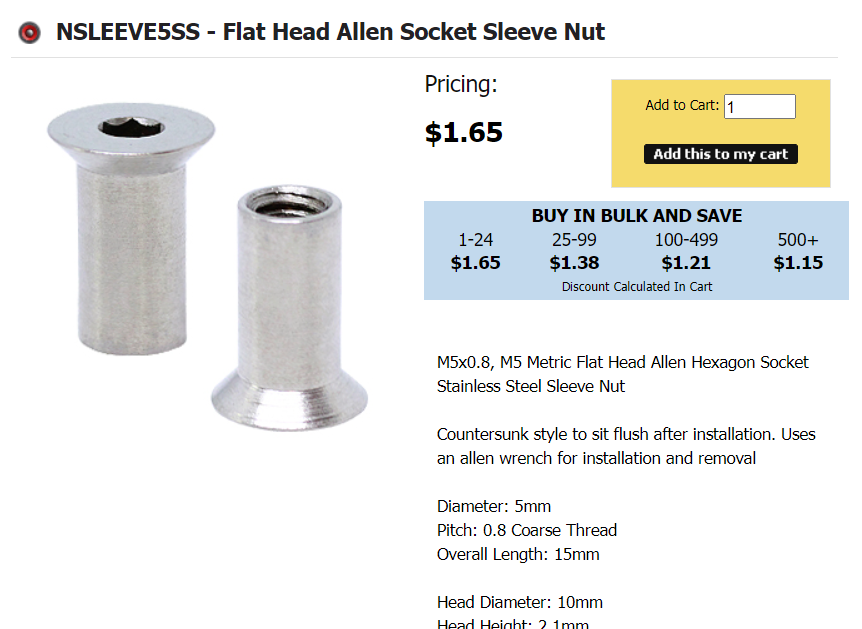
I used these threaded rods and these flat head allen socket sleeves to accomplish my M5x135 SS dreams.
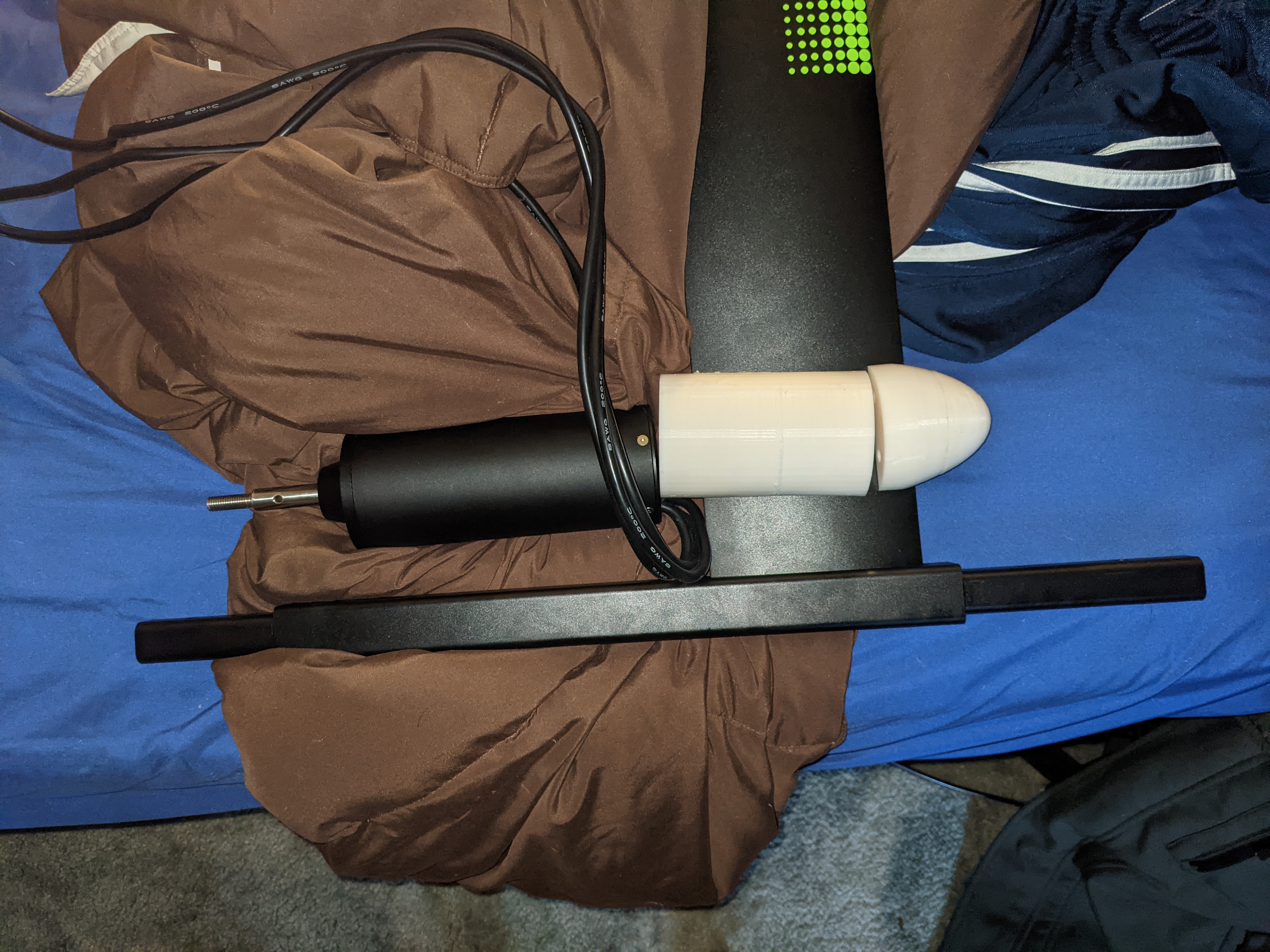
Photos of printed clamp:
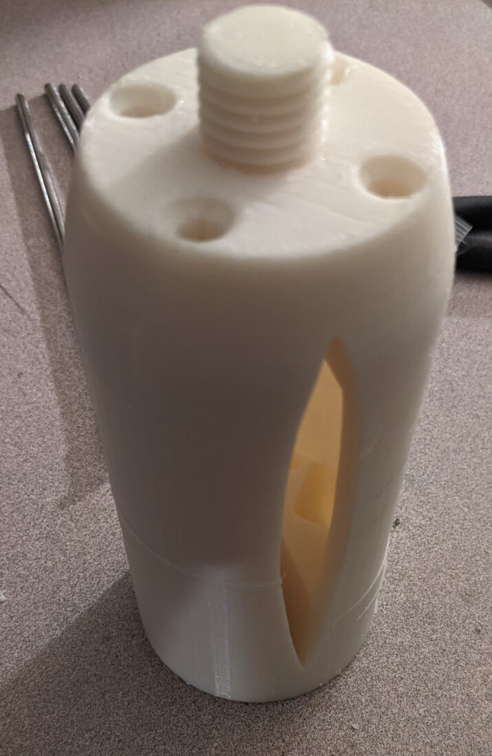
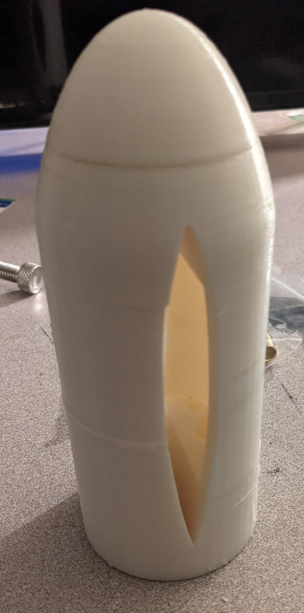
1 Like
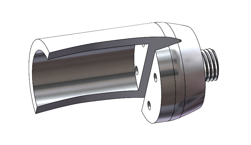
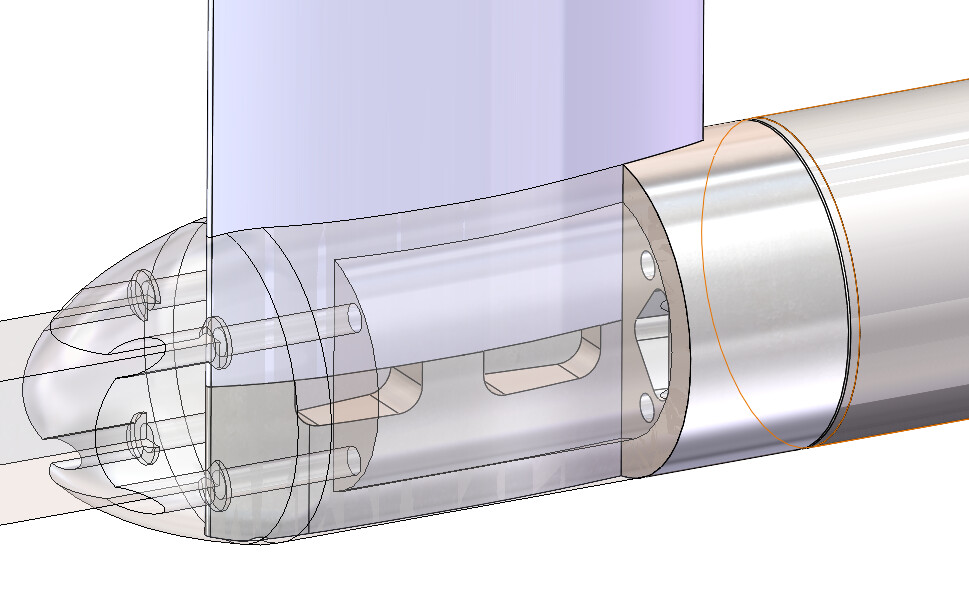
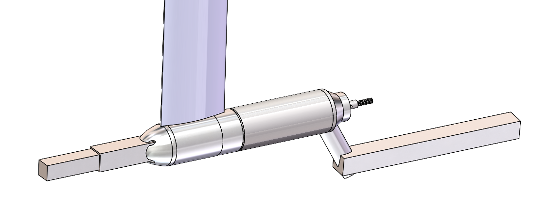
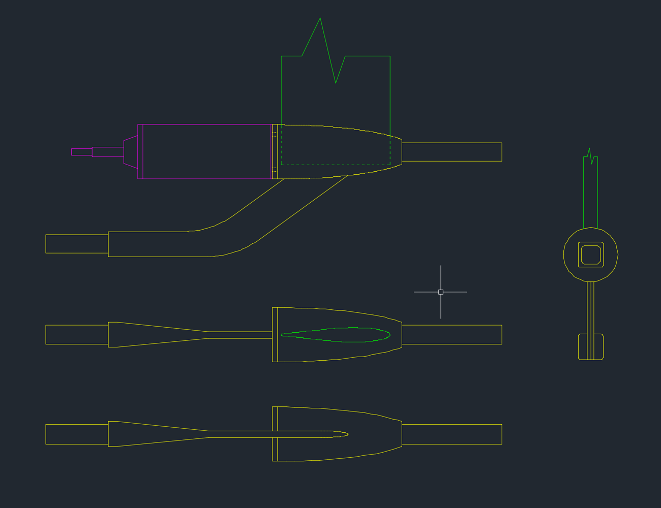
Everyone is talking about the flite board and inplane thrust and its benefits. I was also thinking about how long my 65161 looks hanging off the gong mast. I mocked up a model of a fliteboard copy to work with the gong setup, I think it could work provided the 3d printed parts are strengthened. I think hollow printed and filled with epoxy and fibers would work.
I know the model is sloppy and is definitely not to scale yet… I am unsure if I want to take this path so I did not want to put in a ton of time into details. Some of the shapes could be optimized.
If you don’t put the motor in an aluminium tube, it’s probably better to attach the tail part of the fuselage below the mast, not to the motor.
Like this: New build from 3D printed molds (very low cost, but high performance !) - #47 by visor360
Why? The motor shell should be plenty strong I would think. I was just thinking since it’s already there, might as well take advantage of it’s length rather than add more material for a tail piece if I don’t have too.
And it looks like the flite board attached it’s tail at the motor fuselage.
How do you want to fix it to the motor? There are strong forces to the mast and fuselage, when you ride the efoil. I don’t think the motor case suports this. DIYS and serial production are different things. I also think the Flite is a one piece metal case, the geared motor sits inside. You would need an aluminium tube wirh an ID that exactly matches the motor OD, then weld it. Not an easy task.
You are right. To do it the way flite did, you would have to figure out a way to somehow add something to the outside of the motor tube that is not too cumbersome.
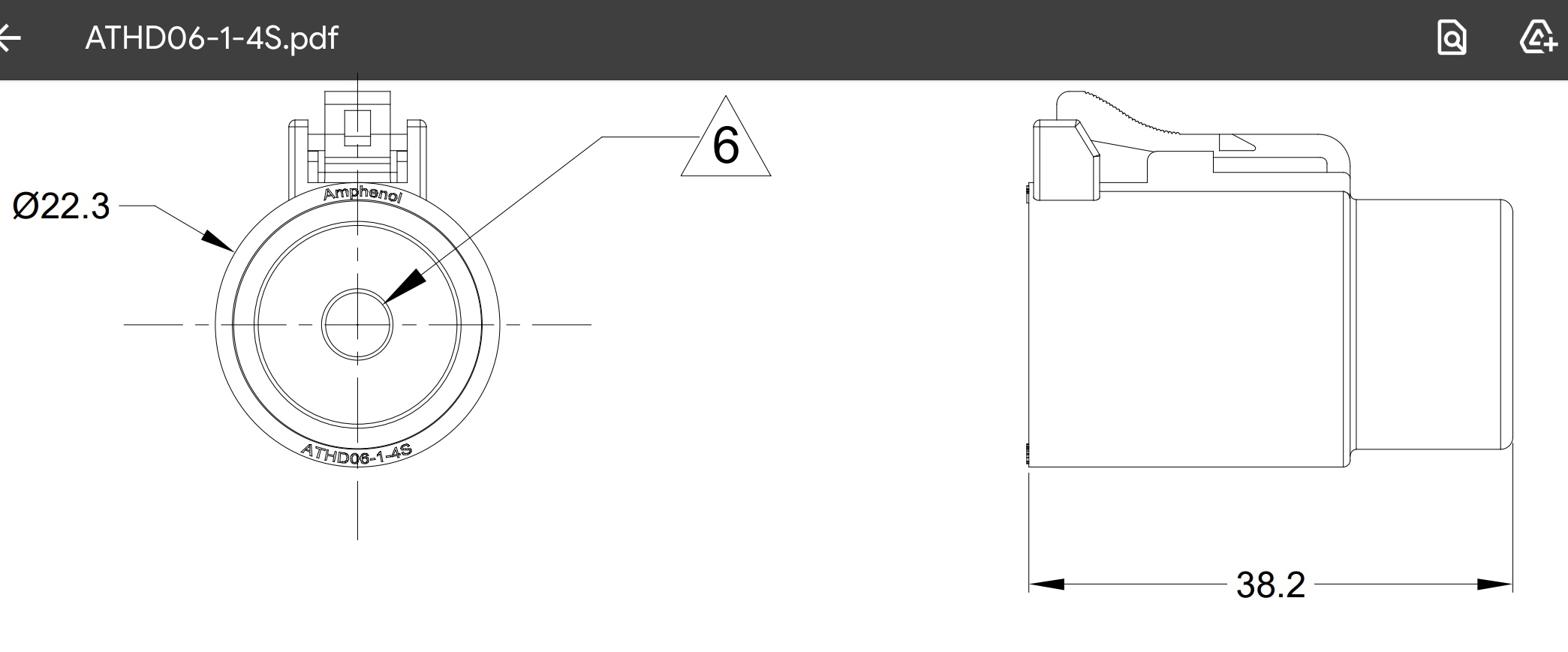
What about mounting the tail boom to the end of the motor in the existing (6) M4 holes?
If I can mount the tail boom on the end of the motor, then my tail boom is short (because the motor is long), reducing the moment forces directly on the tail boom and translating those forces into the motor and motor mount attached to the fuselage (which are strong).
I think the main reason I would be scared to use the motor as a fuselage would be the thread engagement of the (4) M5 bolts in the back of the motor. I think if the rear wing hits the ground or rocks or anything there is fair chance the rear wing could deflect the motor badly and pull the threads out in the back.
Hi, i think you should first sort out where the wires will pass through the mast and fuselage. Then figure out the length of the fuselage. And only finally deal with the rear wing issue.
I’ve been thinking of doing the same thing with a gong mast, Just need my mate to draw this up on in fusion 360 and 3D print as a negative to use as a mould to make it out of CF.
1 Like


