Oops. I meant the 65161 120kv.
1 Like
I’m having trouble visualizing your idea.
To me keeping the Lift impeller at the same location within the duct would be very important for it to function as designed.
Can you do a simple sketch of how the components would fit together?![]()
I agree, it must. But the whole assembly will need to be set further back from the motor to make room for a mount adapter and a propeller adapter.
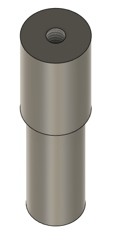
If I figure out something of course. But for now just noodling (with the render above) what the interface element connecting Flipsky shaft to Lift prop would look like. The top piece is the interface element the bottom tube is the Flipsky shaft.
Here’s one for $225, just happened across it. I bet you can make it work once you buy it and are committed!
(Sorry, just realized this Facebook link might not work)
Interesting.
My thinking was that IF the rear portion of duct (the portion that connects to the motor) fits over the 65161 motor shaft the hole in the prop could be altered if necessary so that it slides over the shaft so the position of the “thrust pin” (not sure of the correct term) aligns with the existing shaft through hole. Then a normal nut could be tightened down against the pin.
This rear section could then be positioned to where it would normally be in relation to the prop.
That might leave a space between the end of the motor and the rear piece of the duct where an adapter would be positioned with appropriate mounting holes. That part could be 3D printed so cost would be minimal
Of course knowing the dimensions of the Lift motors drive shaft would help determine if that would work. I can’t find any of that info.
You can just modify a lift prop to fit the 65161 motor.
Thanks @S_Roger – I bought it and now yes I am committed!!
Now we all will have access to detailed photos, measurements, etc.
5 Likes
That’s great! Any timeline on when you expect
to have it in hand?
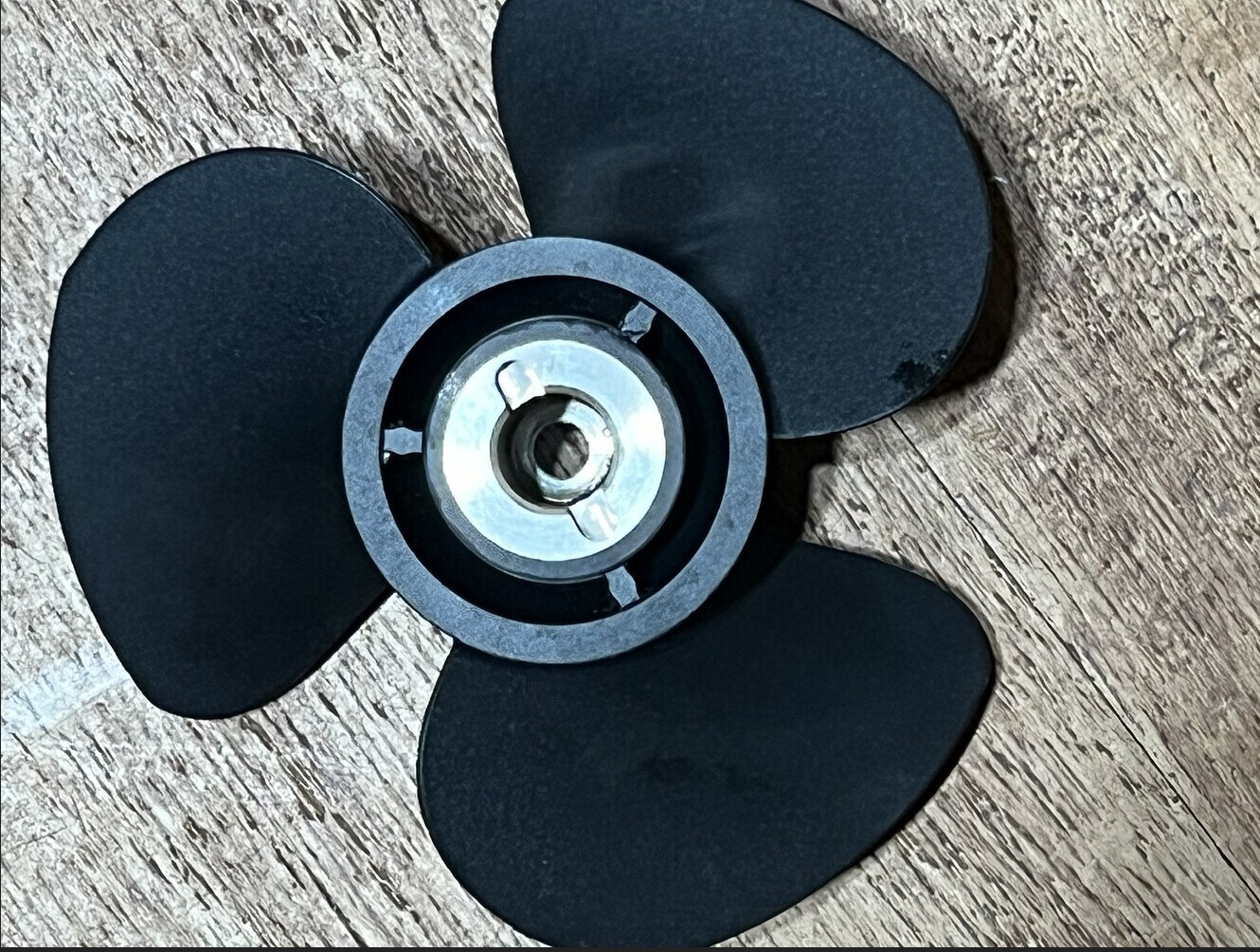
It’s really well built, feels super solid, it’s all anodized aluminum with a stainless steel insert in the impeller.
To fit it to motor may be challenging. I can see a threaded stainless steel adapter having 12mm OD and a built in pin-feature to lock to register the impeller to the adapter.
1 Like
Also, not sure if this site is legit but this site has new Lift Jet for $299 in case anyone is game
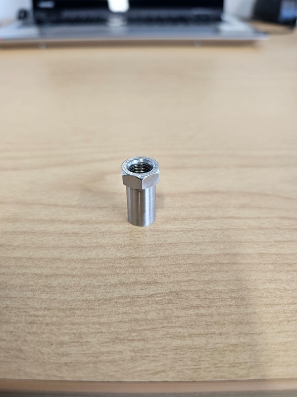
A friend adapted a Lift toroidal prop (efoil solutions brand) for a 65161.
I think he drilled the bolt hole to 8mm, then made a nut like this - machined down off the shelf long nut from a stainless shop.

Very interesting thanks for sharing that.
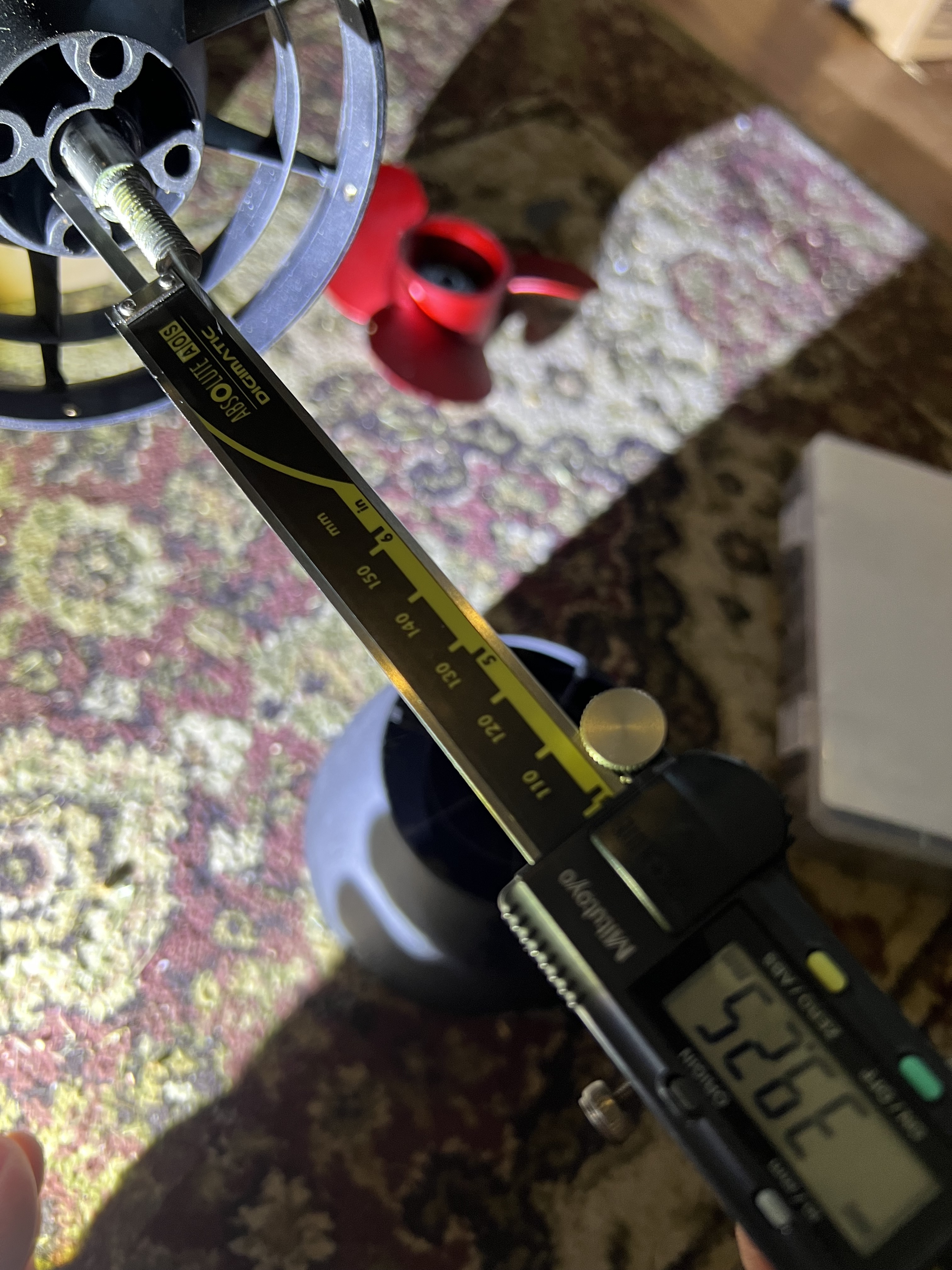
The first adapter to interface the jet housing to motor should be easy. For the prop adapter there is just over 39mm of shaft to work with.
I am thinking about milling the impeller adapter out of POM.
Here’s another couple of ideas.
I printed a spacer for a guard and then re- drilled the holes at the correct PCD.
Does the lift jet line up ok with the screw holes?
Looks like you should be able to get it to work ok.
2 Likes
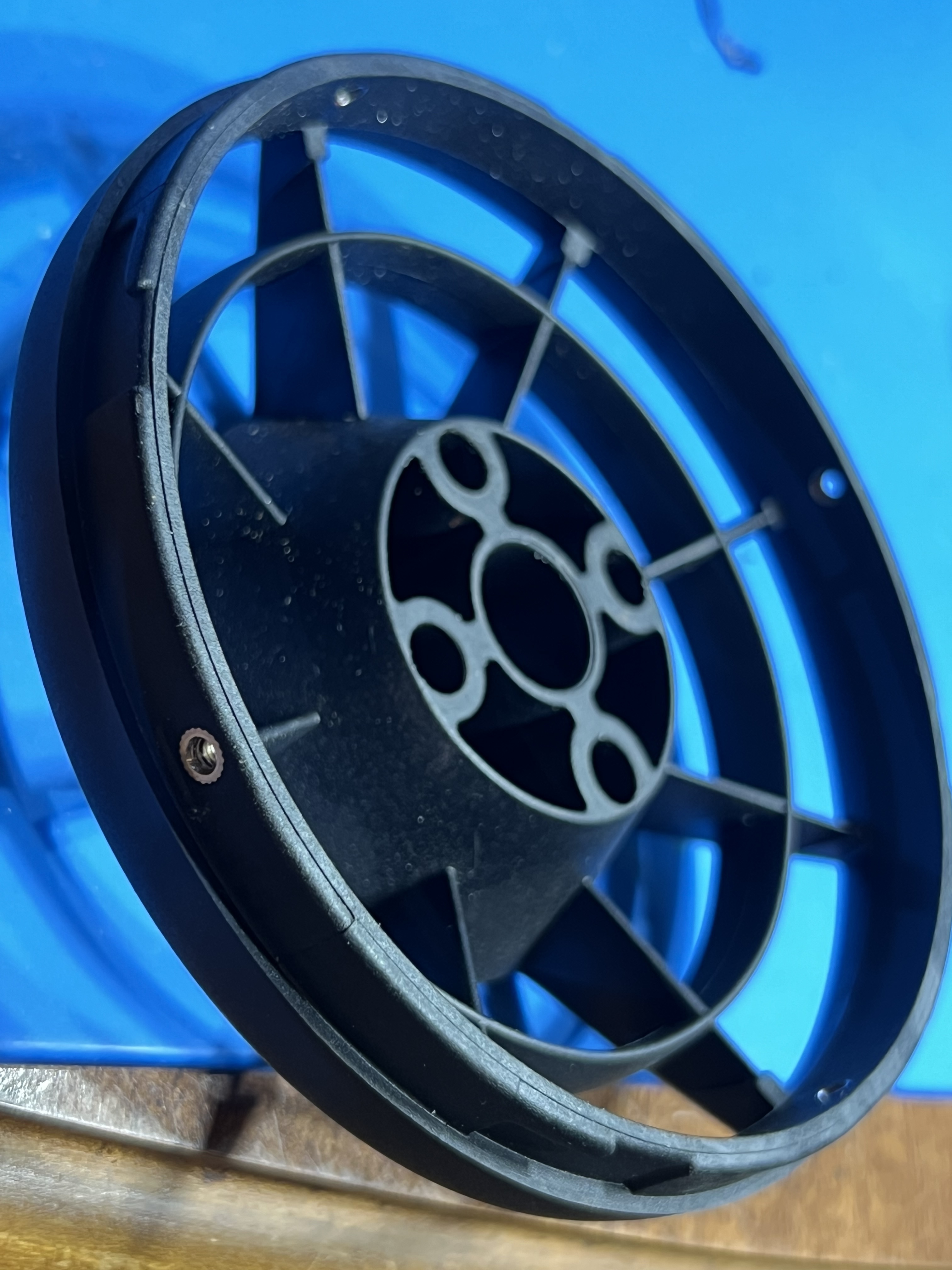
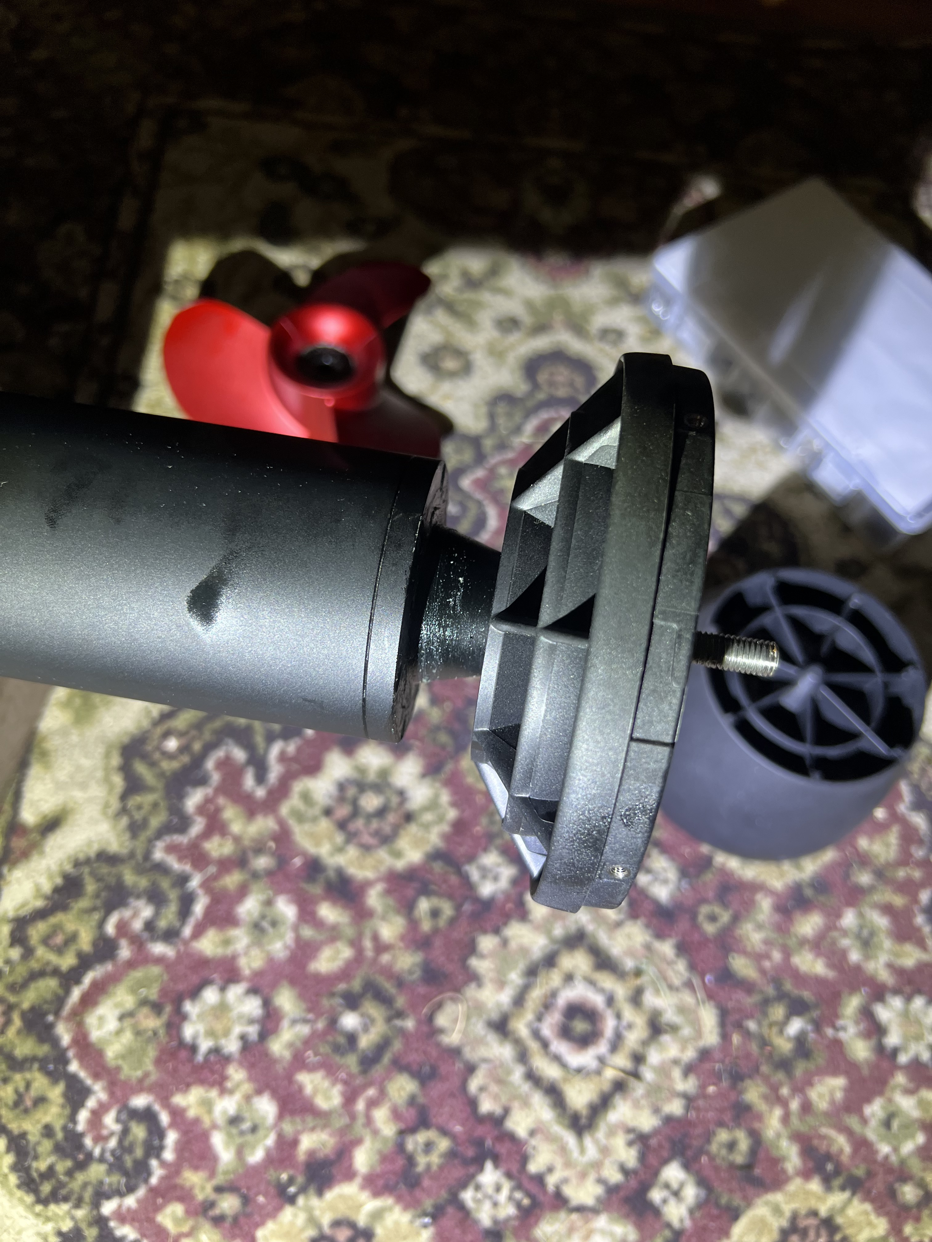
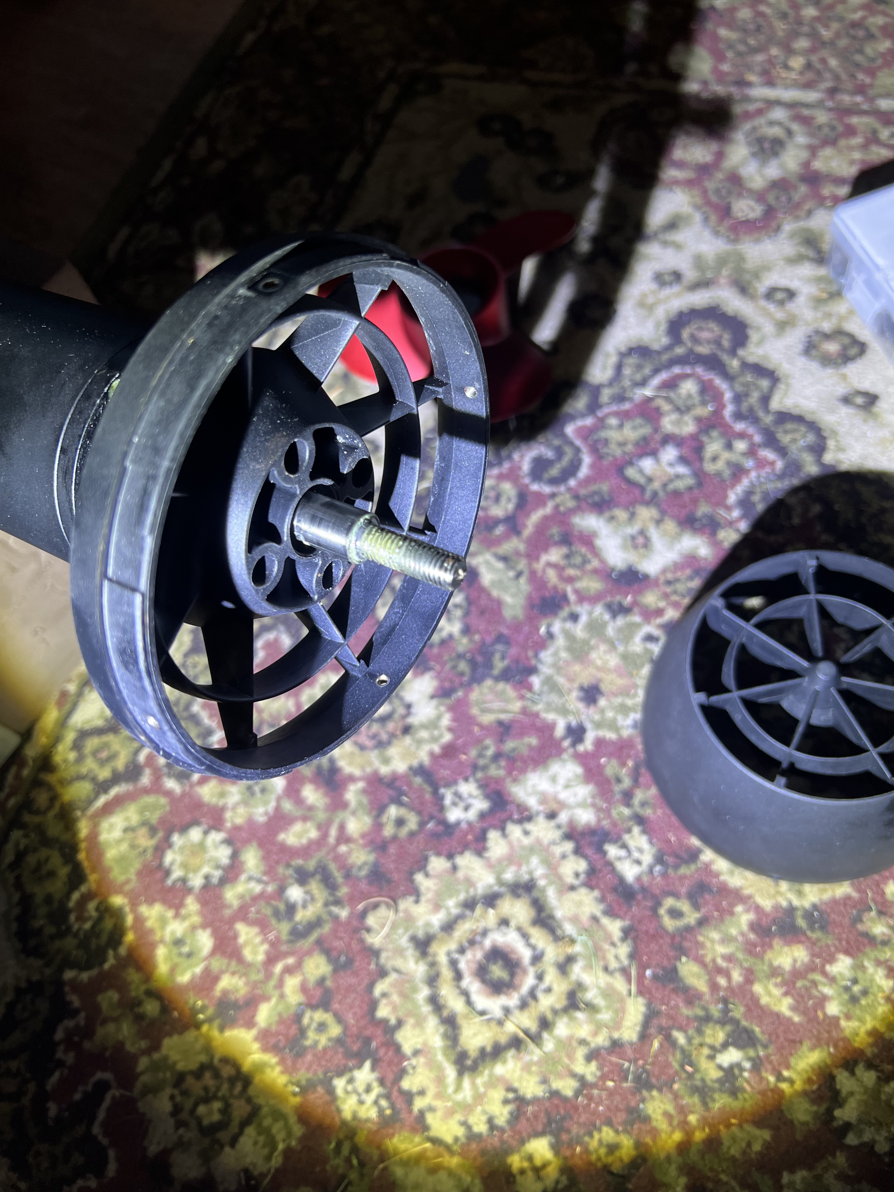
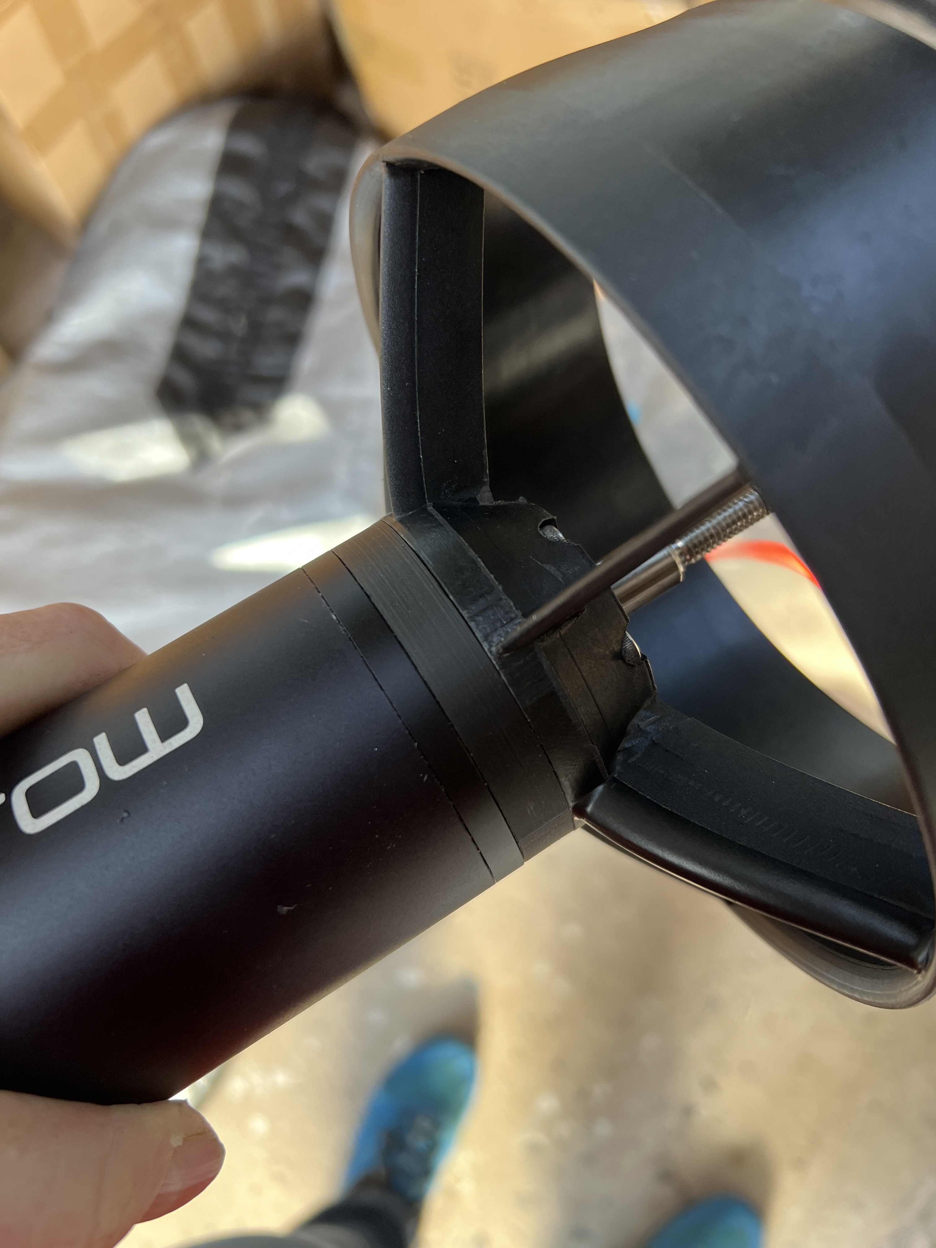
Cheers mate! They do not line up however this is exactly what I was going to do for to interface the Jet housing to the motor. ![]()
![]()
And for the impeller side I see a path using permanent loctite to bond (a) thread reducing nut (female M5 to M8 male) to an M8 coupler with 12MM OD to extend the shaft and convert the entire shaft to 12MM with the very end being M5 threaded to receive the Lift Jet M5 mount bolt. Now need to find a way to weld some nubs on the outside of the coupler to lock the impeller to the adapter at the proper location. It’s coming along!
Thanks for the photos and measurements.
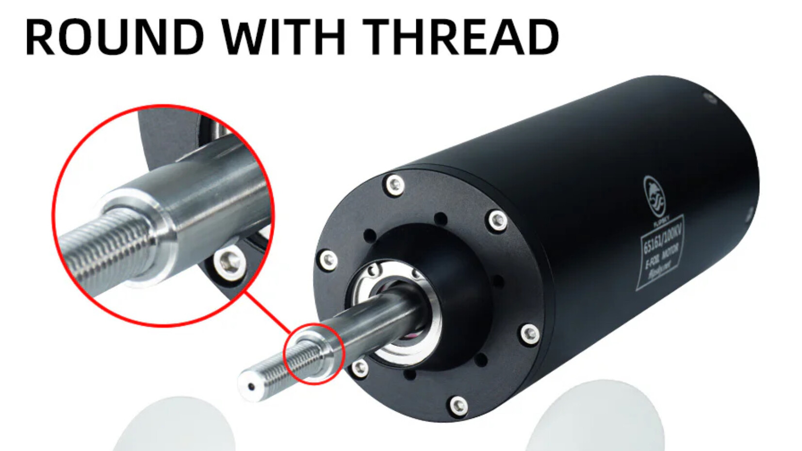
I pulled these screen captures from Flipsky that might aid in the discussion
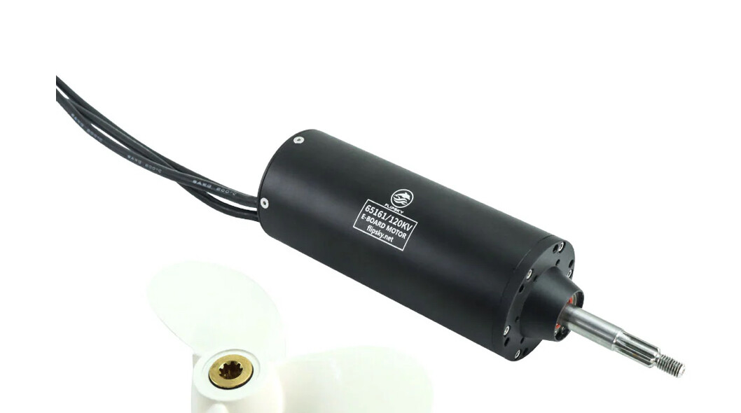
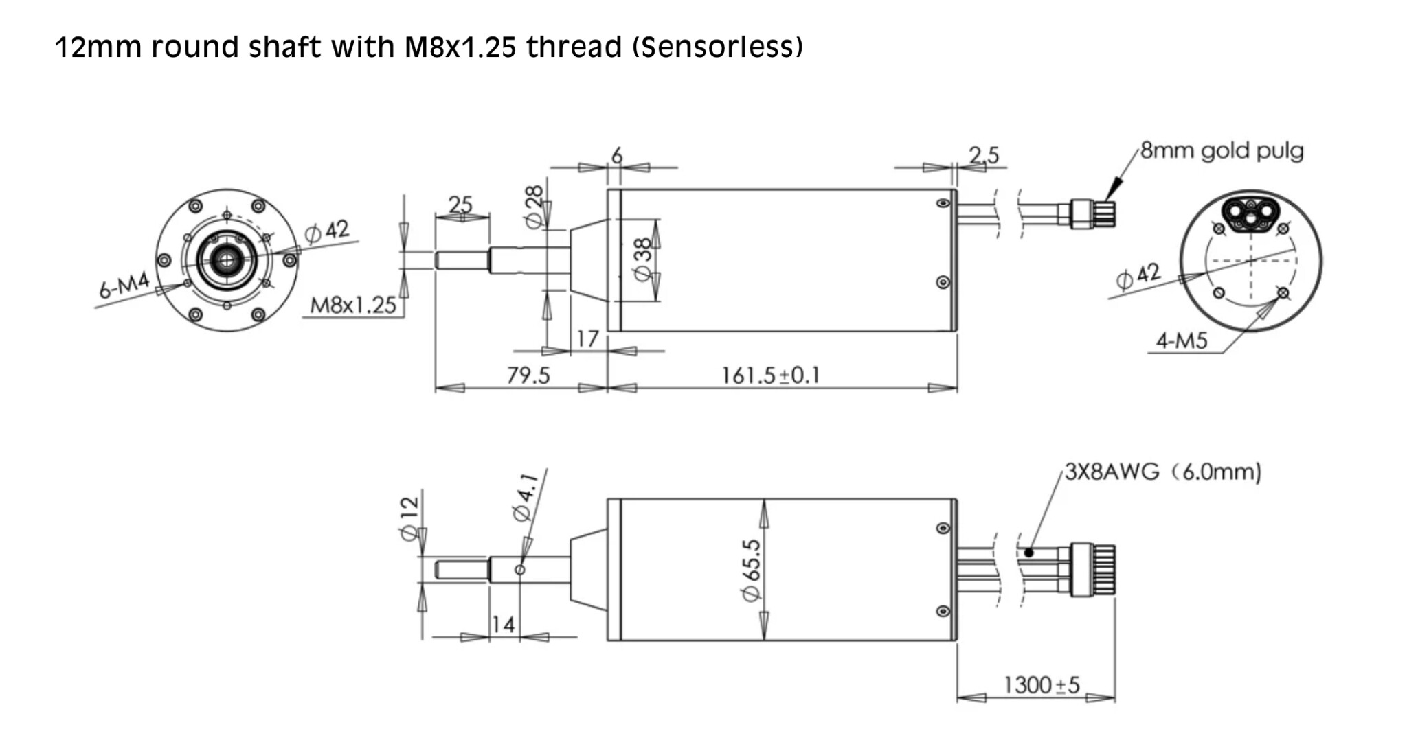
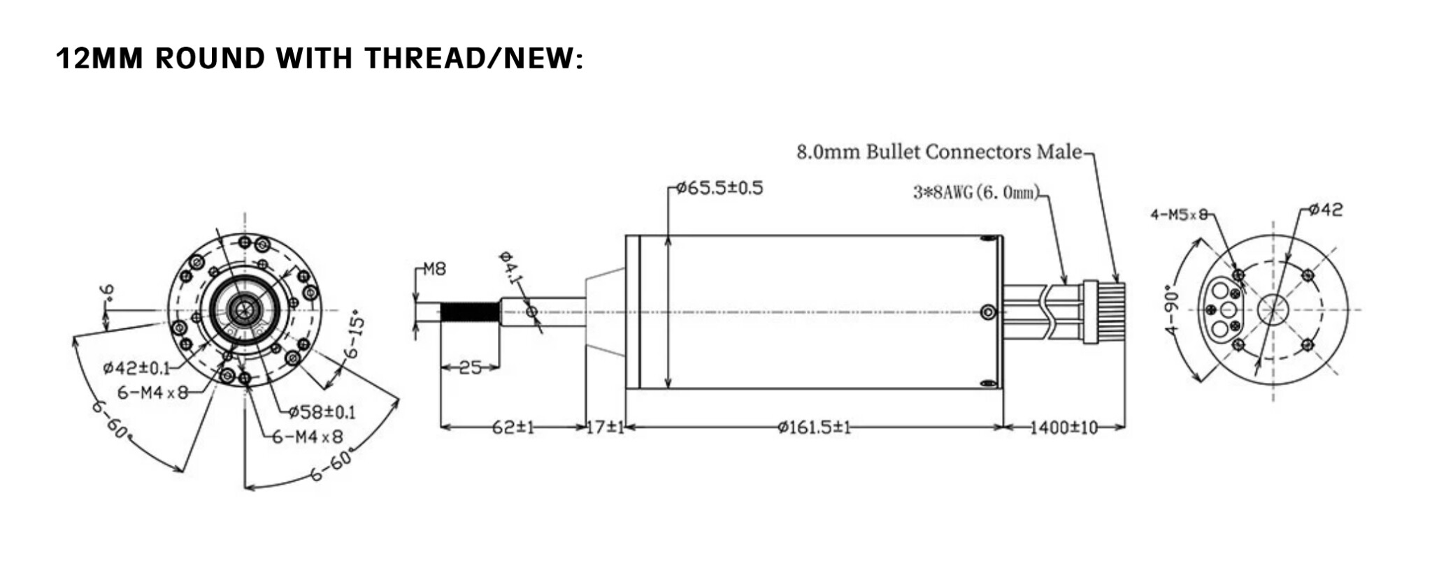
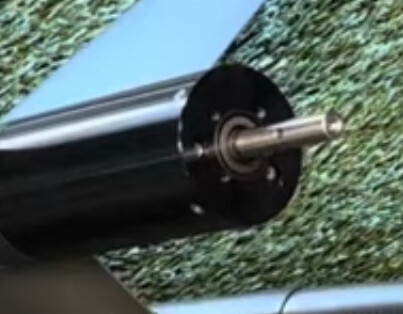
And the screen grab of the Flite motor I posted earlier
I have a few questions.
-
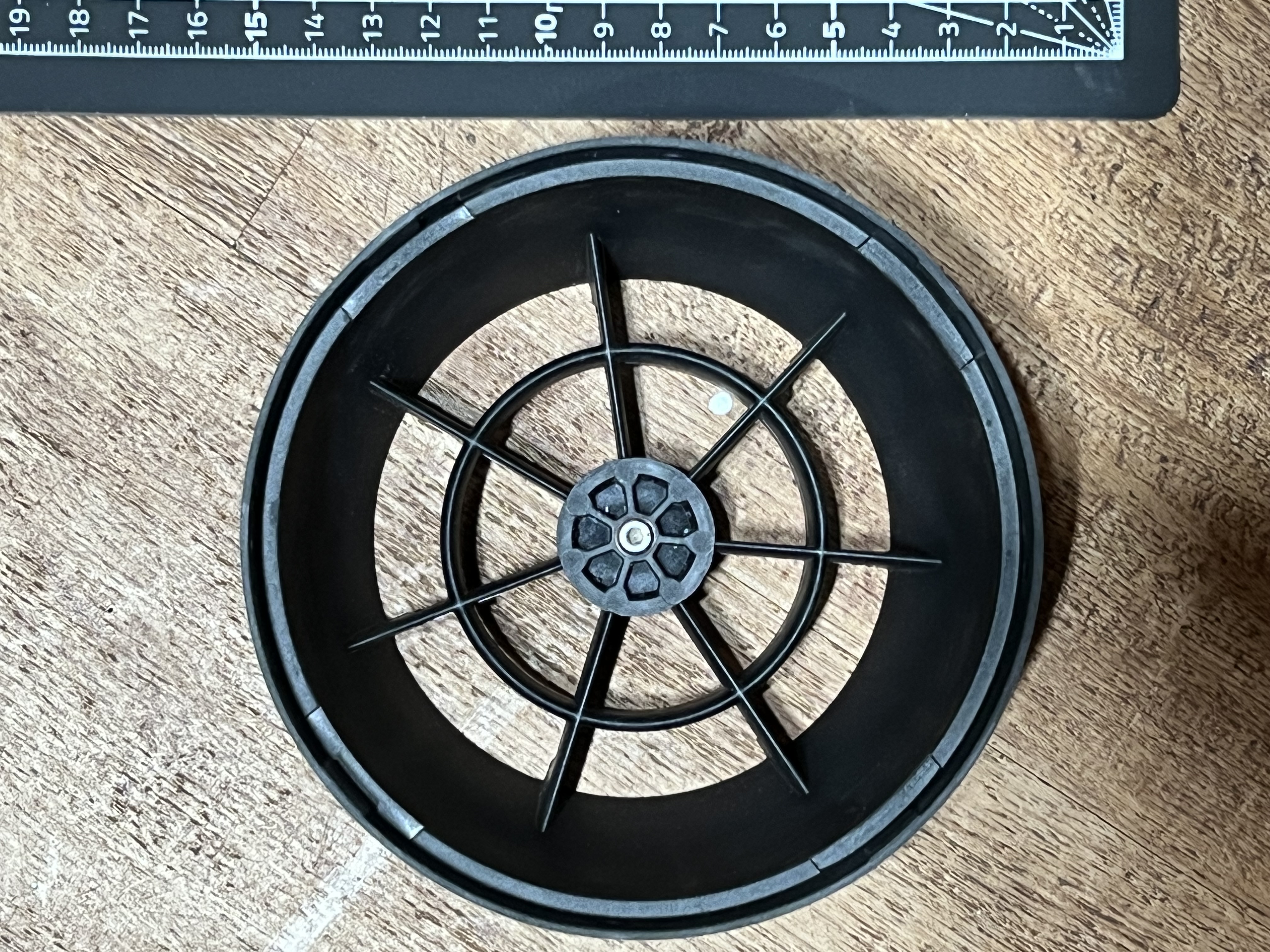
what is the total length of the two duct sections when assembled?
-
the diagram I posted from Flipsky indicates the “bump” on the end of the motor face is 17mm. Is that an accurate measurement when you have the duct placed against it?
-
When the first piece of duct is on does it cover the existing hole in the motor shaft? If not we will need to drill and new one. What size of pin does Flite supply with the jet drive? Do you feel there is any issue from a 65161 shaft integrity perspective if the shaft ended up with two holes and should they be in line or offset by 90 degrees?
-
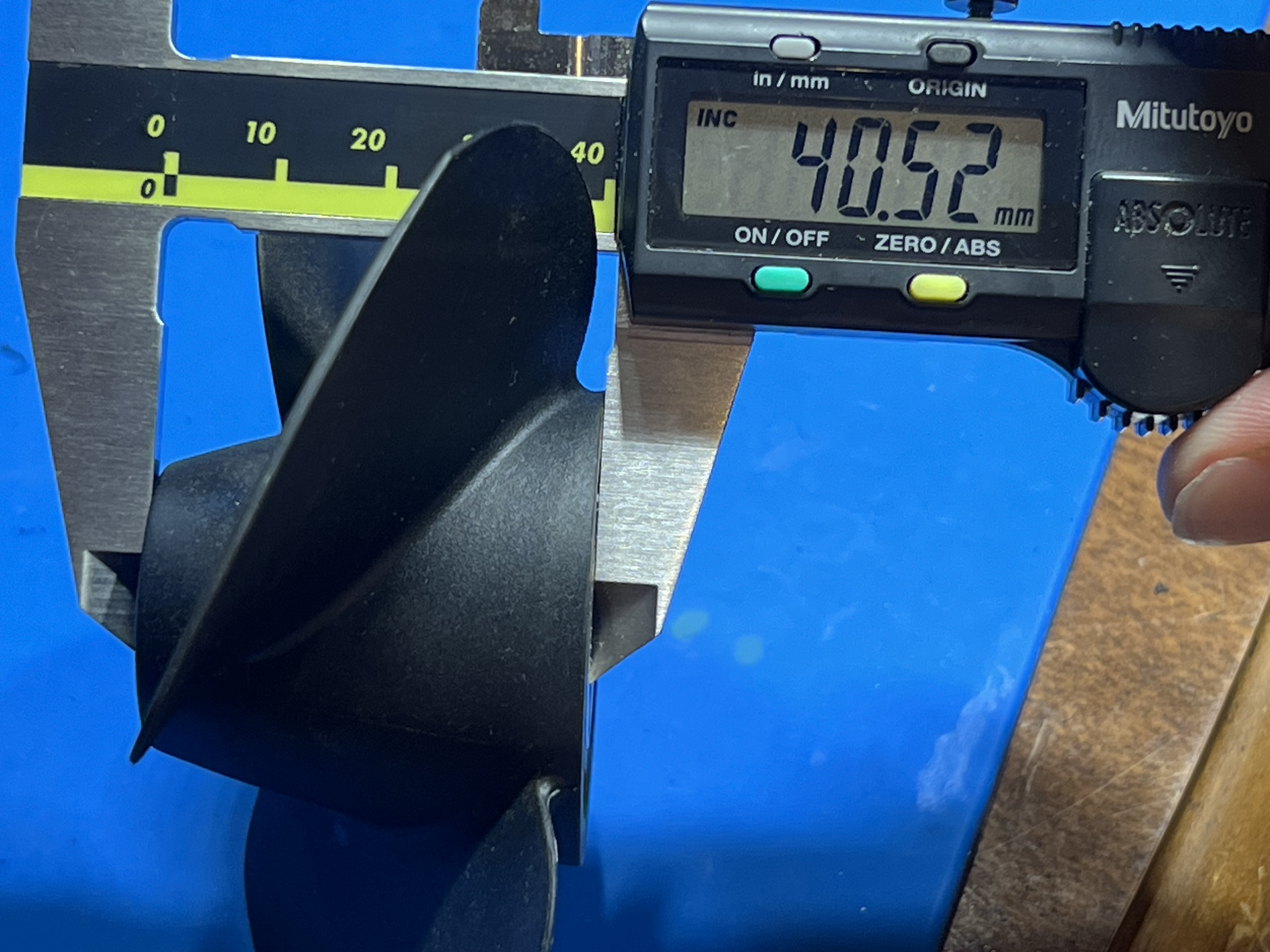
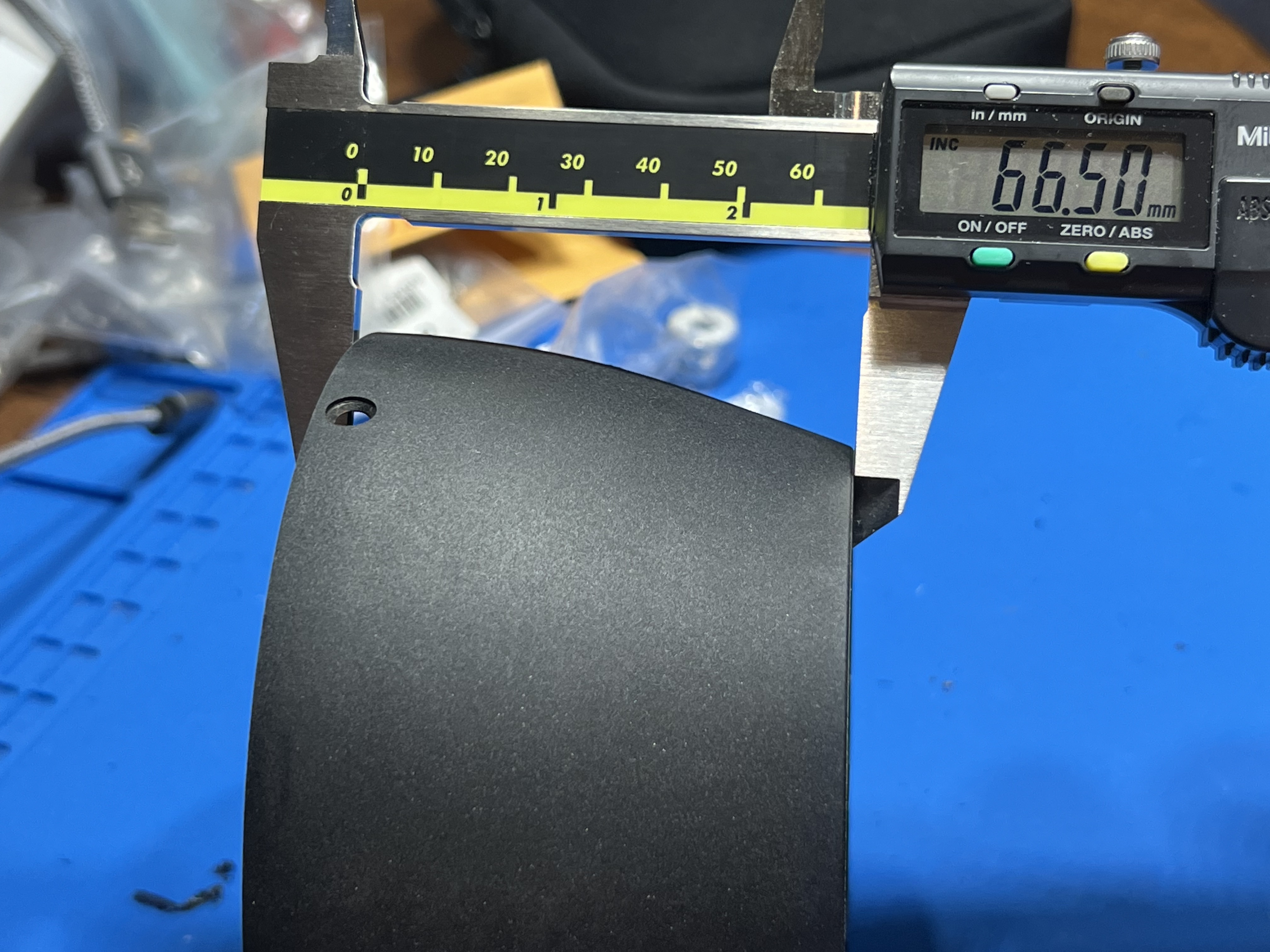
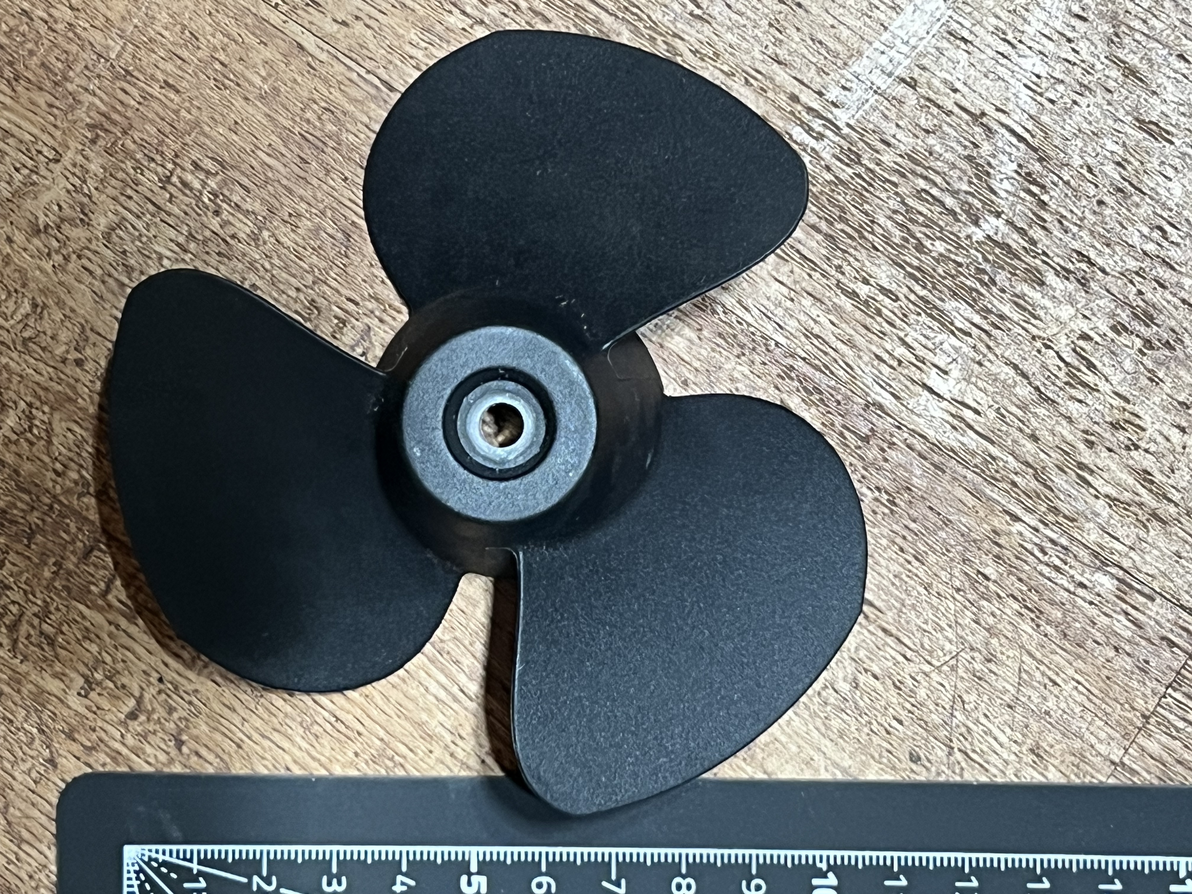
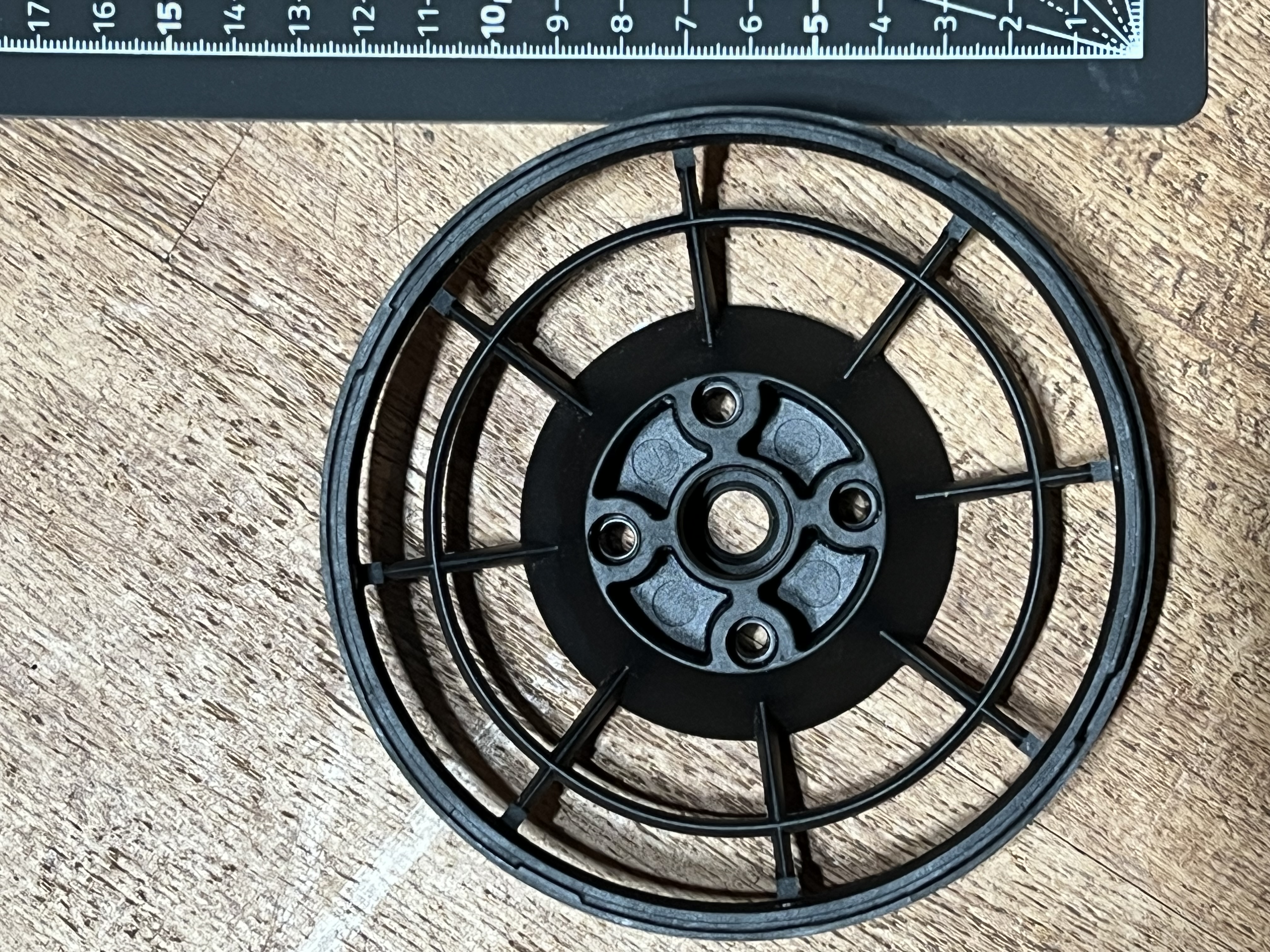
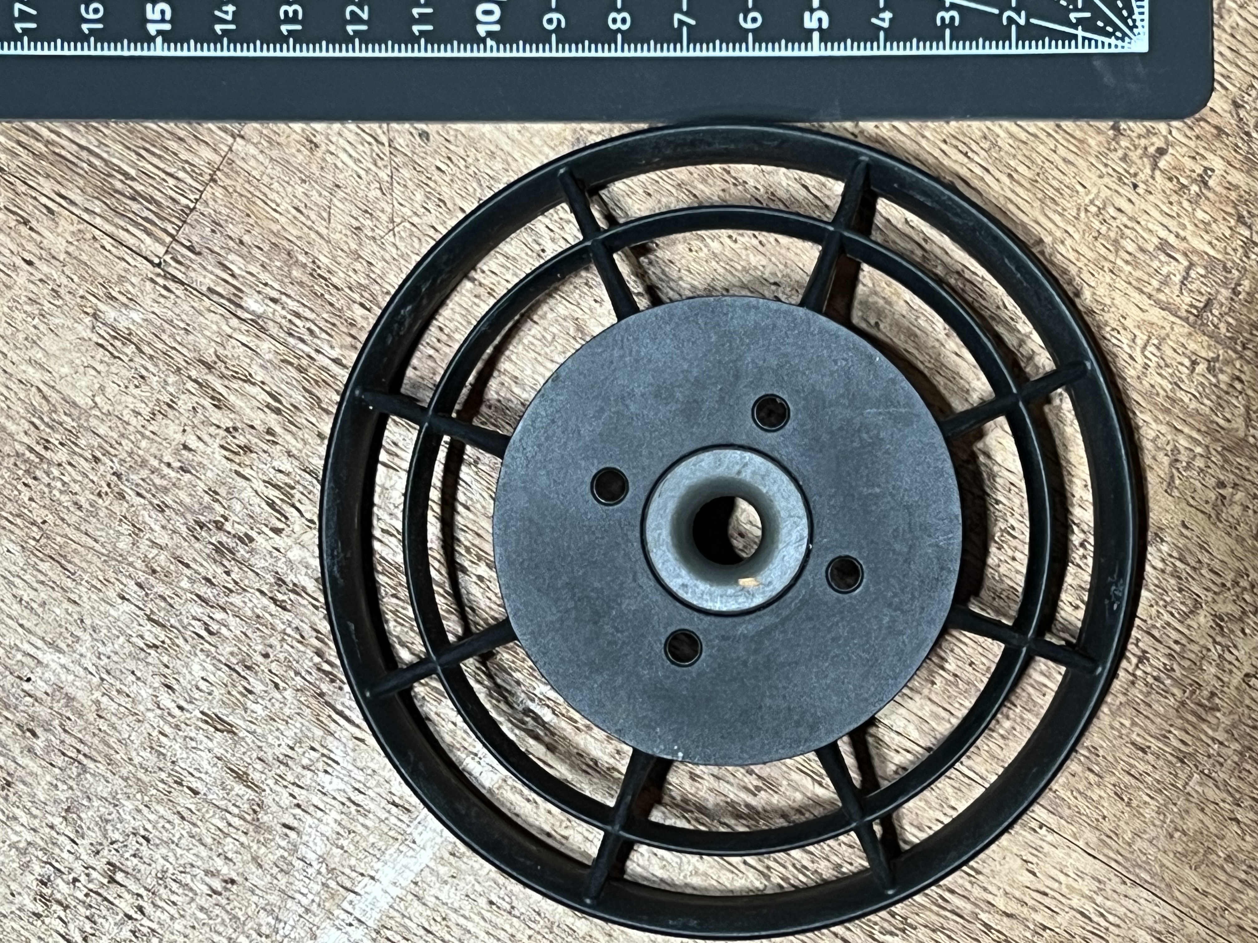
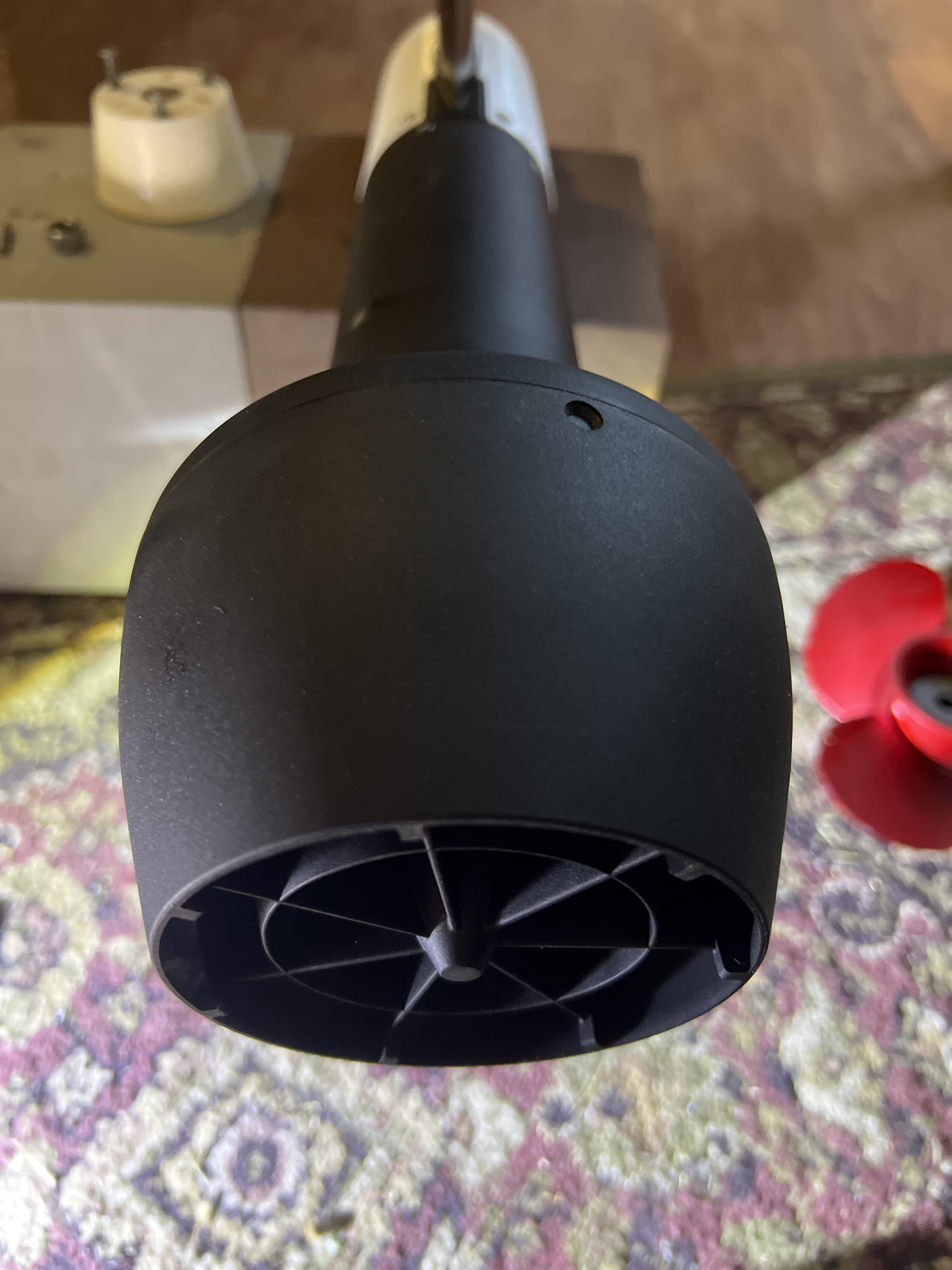
can you provide some additional measurements of prop such as diameter(s) and depth of center hole?
93mm
Yes
Partially, yes.
The Lift motor appears to use 4mm.
Not sure. I want to avoid modifications to my motor, shaft and impeller. I think its possible to use the original prop mount hole and interlock the pin into a shaft extension assembly. Not sure how much risk to extending the shaft (and moving the propeller load further away from motor).
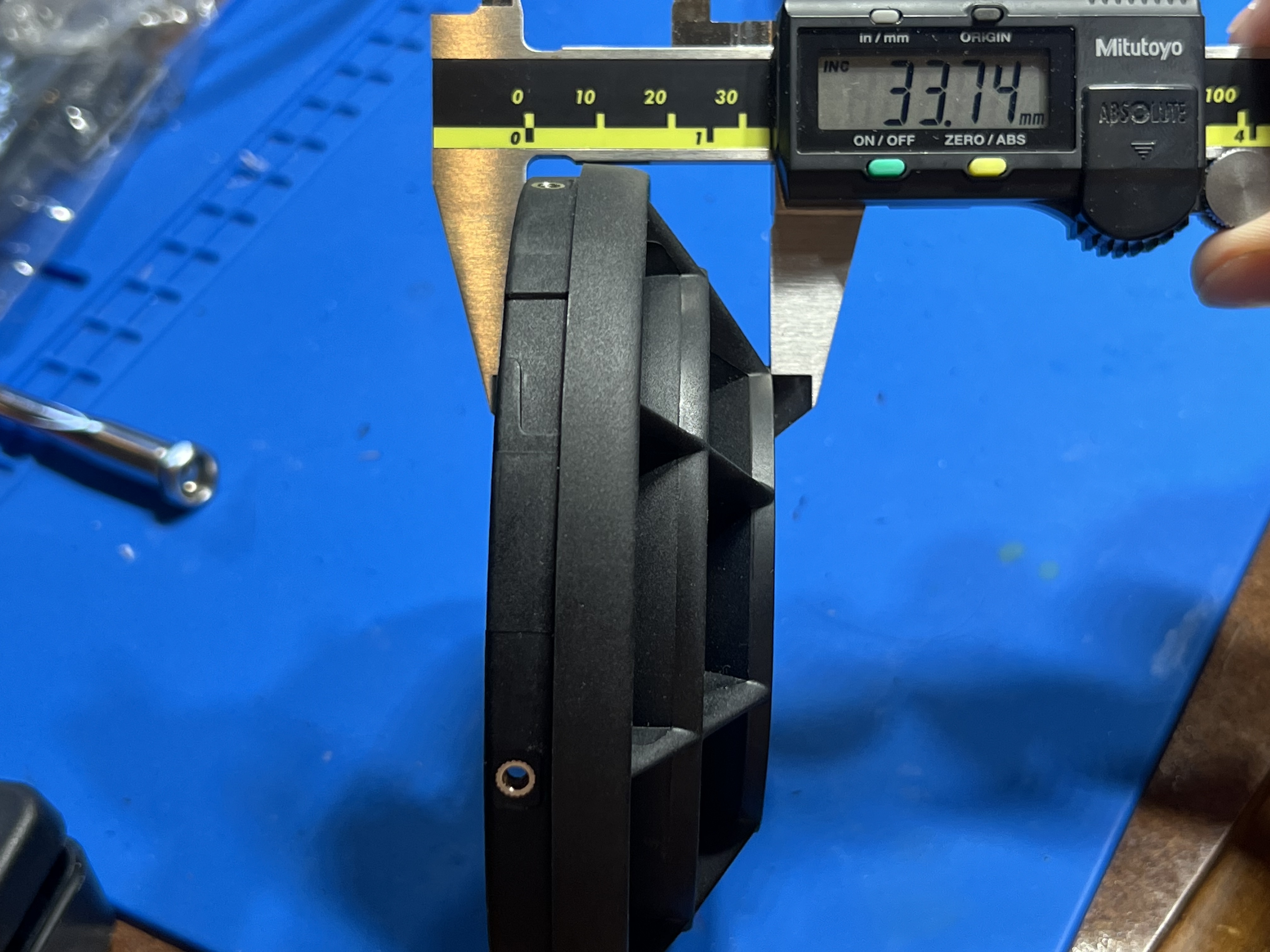
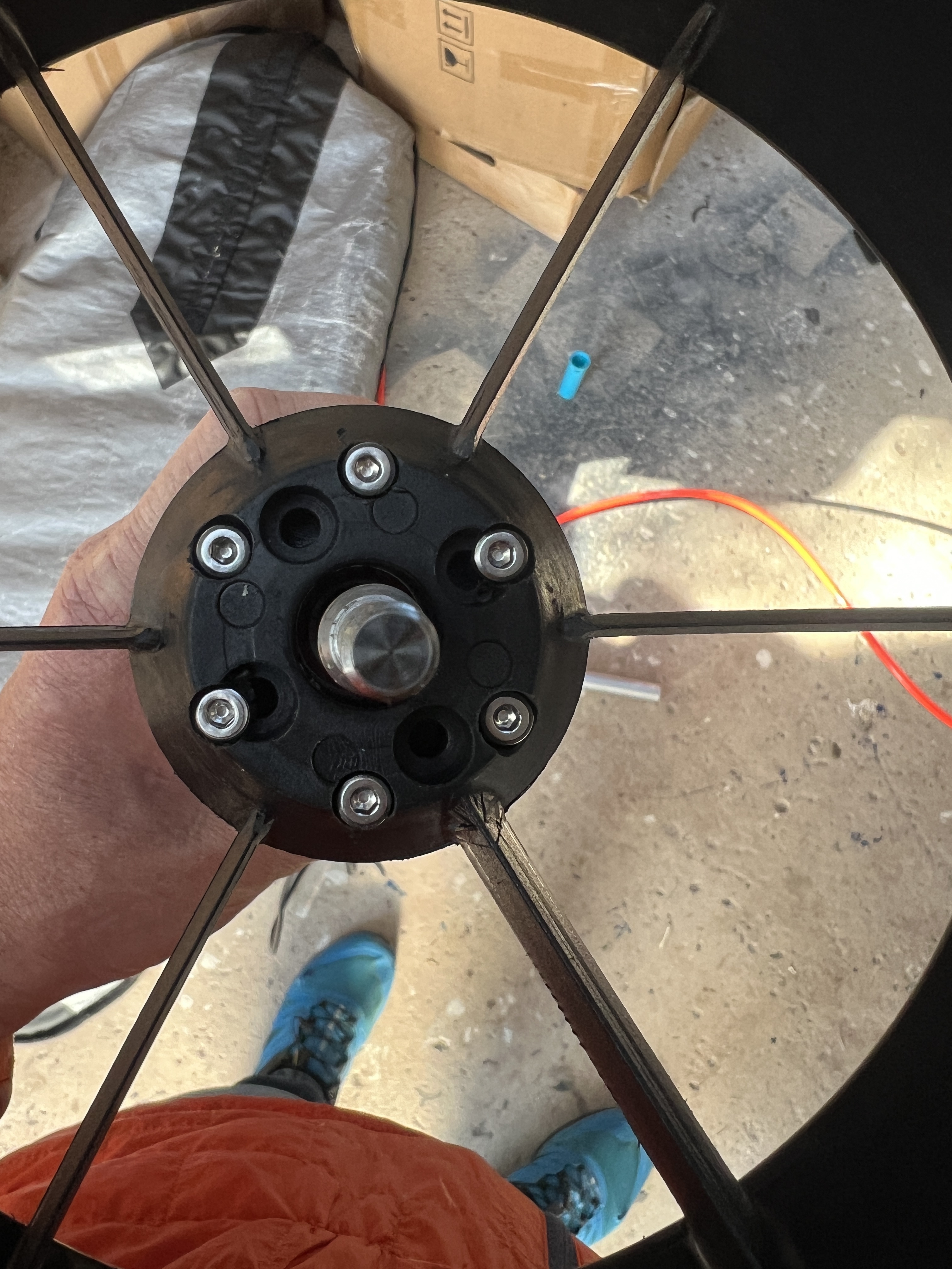
108mm Diameter of impeller
6.5mm Depth of impeller front face center hole ![]()
![]()
1 Like
Gary thank you for all of this info! Very helpful as I try to visualize an approach to getting this to work given my limited skill set😀
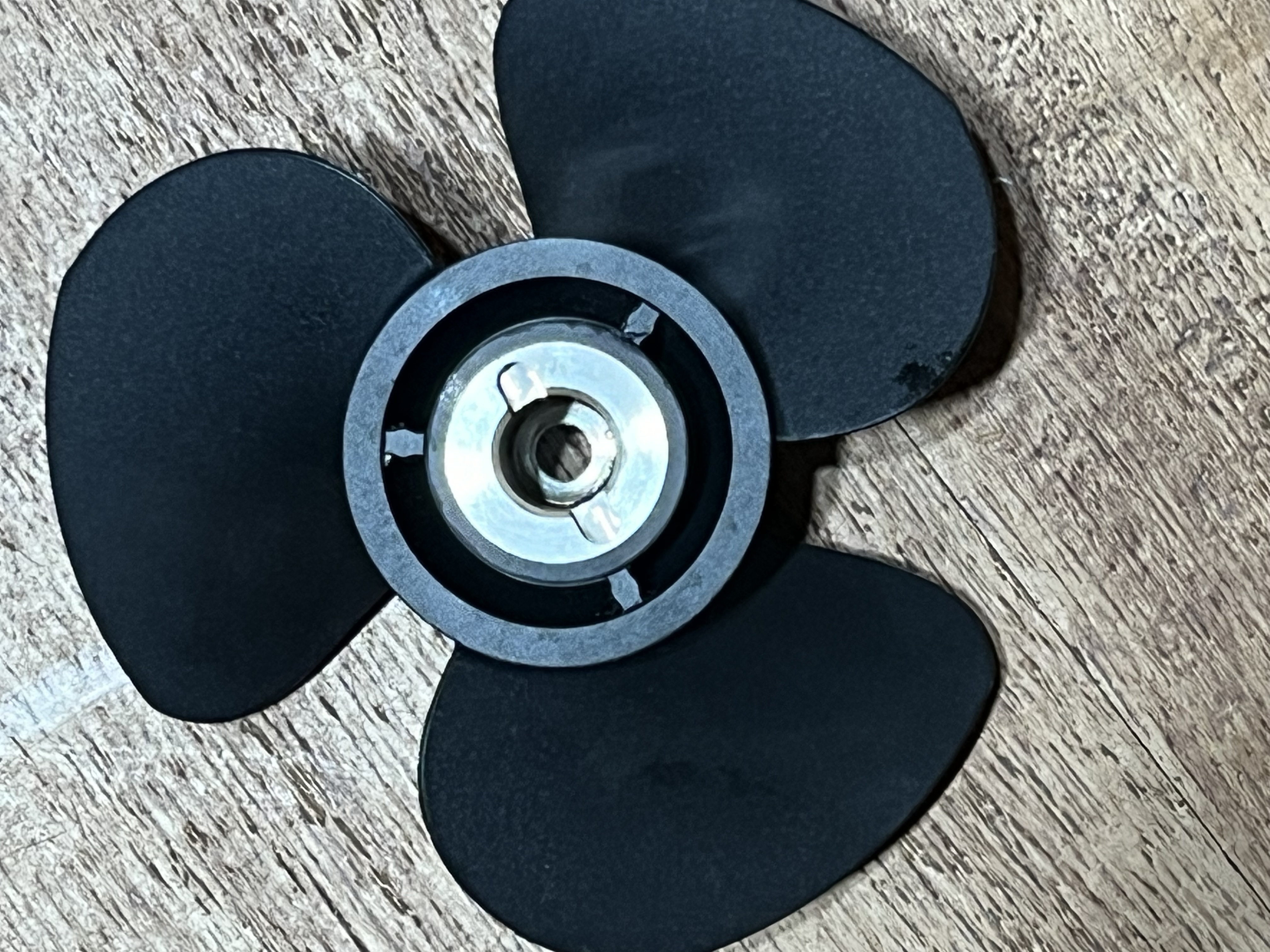
If I may ask for some additional info on impeller. The stainless insert has two diameters in it.
I think the larger one fits over the Lift motor shaft end and bottoms out when it reaches the pin and the smaller one allows the Lift “retention” bolt to be inserted.
Can you provide measurement info of those holes from the perspective of the photo you posted?