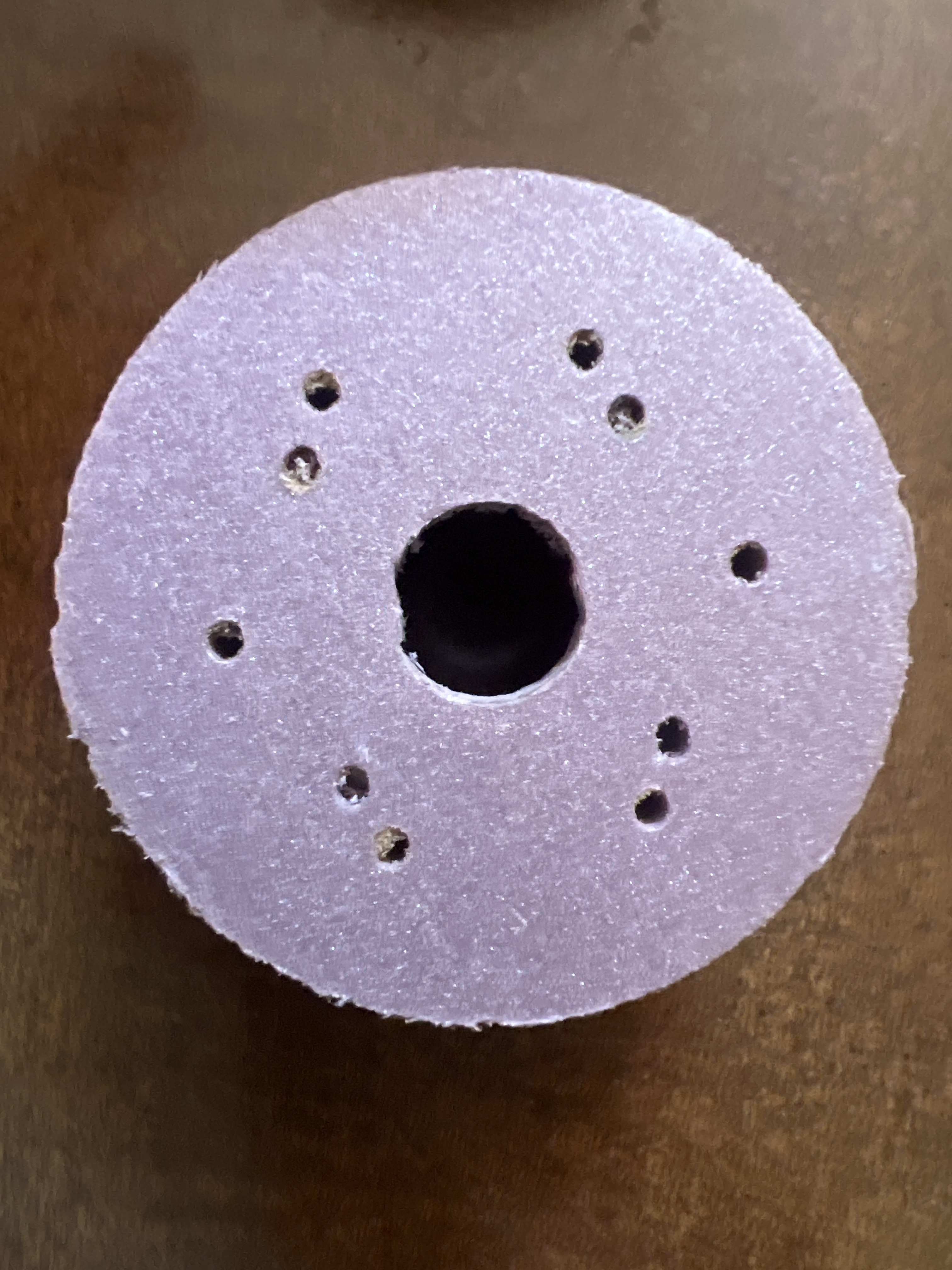
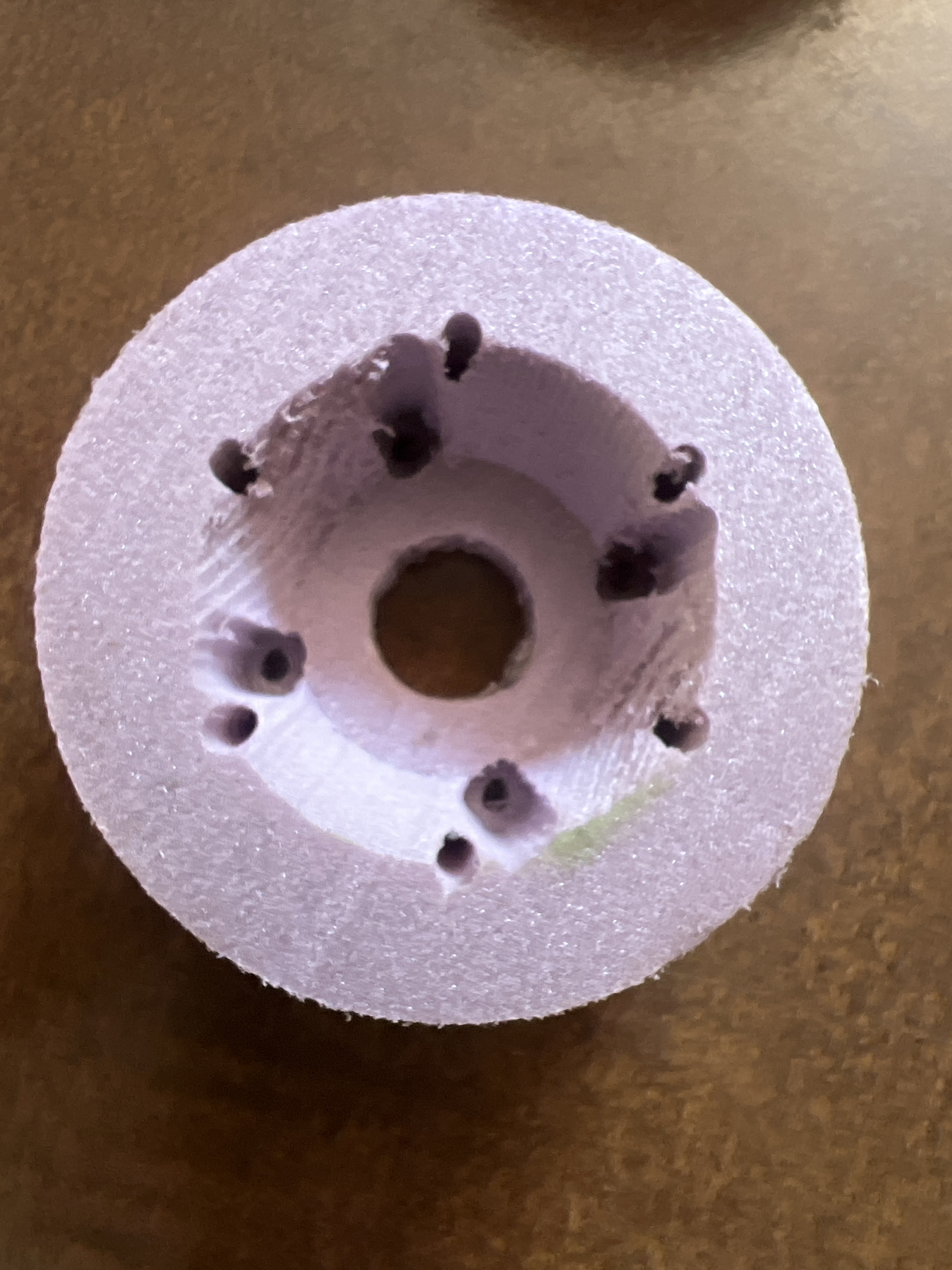
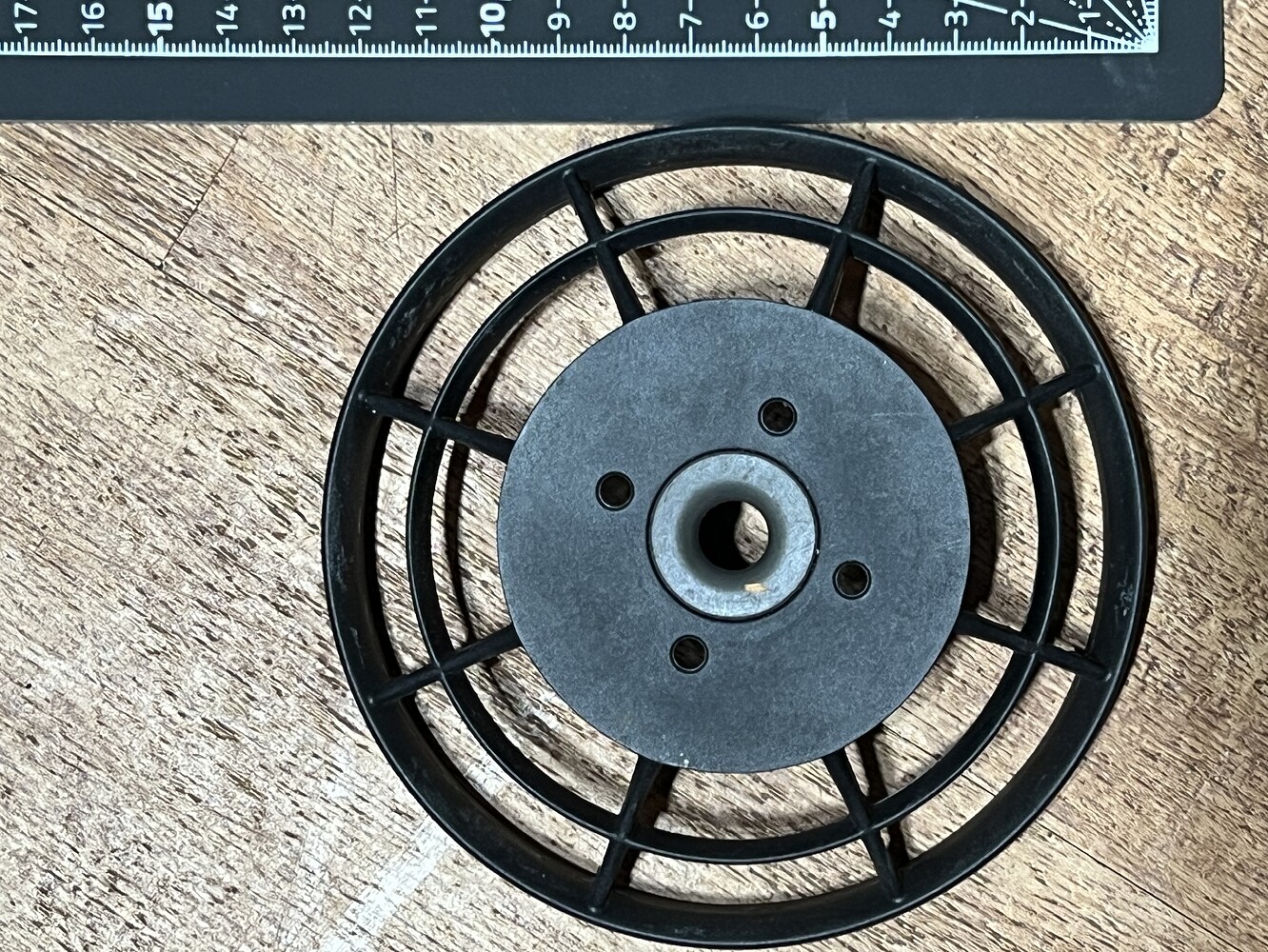
Sure. The big hole is 12mm. Smal hole is 6mm diameter. Smaller hole starts at a depth 28.3mm below the plane of the big hole. I have a solution in the works that seems to pencil out let me share it…
1 Like
Going to mill the mount out of POM plate. The other parts are all from Amazon and just need to be tweeked, knotched, etc. I will elaborate once I confirm it all works!
1 Like
I was thinking of the same kind of thing as the attachment of duct to motor body. ![]()
I have an stl of a duct that I got from someone here on forum for this motor.
I stopped using the duct but I used the motor end section to create another stl that I use as a filler between motor body and Flite prop I use now.
Are you thinking of machining the part from metal or 3D printing it?
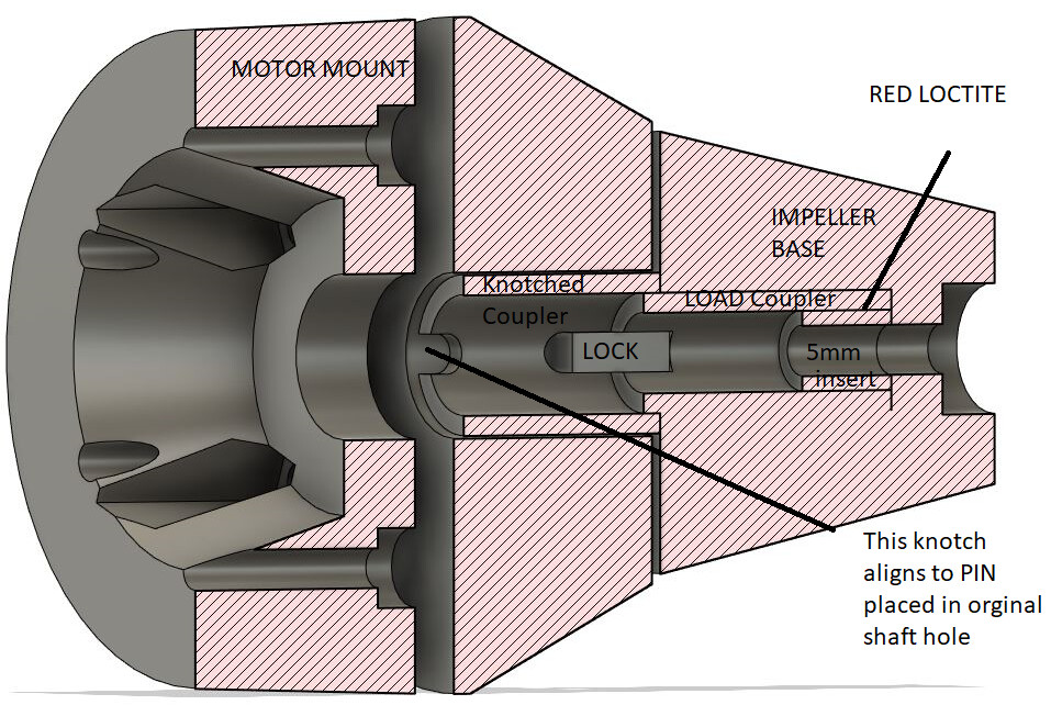
The solution I have requires no changes to the motor, shaft, impeller, and just needs to cut two knotches in lift jet housing on the side that mounts to the motor (so it can pass over the 4mm lock pin that is installed in the shaft before putting the impeller “assembly” together.
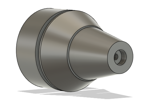
The assembly is a concoction of stainless steel couplers and inserts and two opposing locks that tie the forces from the shaft pin to a shaft extension that has a receiving hole for the original Lift Jet impeller.
The only problem I see is it adds about 16g of mass at 40mm further away from the motor so I am not sure if this is good news for the life of the motor and and imperfections and imbalance from hand slotting some of these peices may make an eccentric mass and amplify vibrations…
Thanks again - you are very generous by sharing this info😀
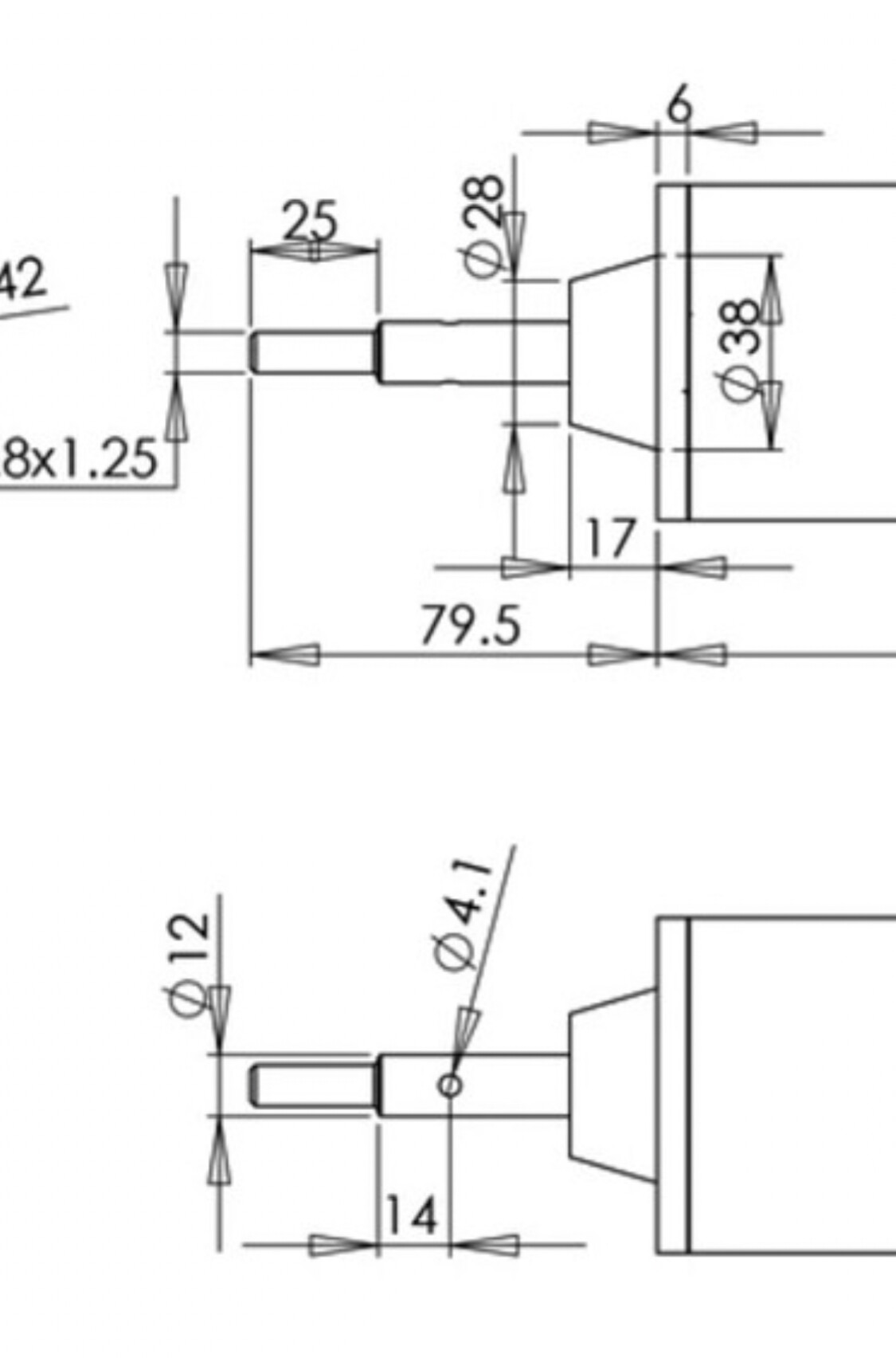
So prop would fit over Flipsky motor shaft at the 12mm section and the pin slot is already there.
I don’t have the machining skills or knowledge that you have displayed in your plan so I might have to go a little basic and ream out the 6mm section to bring the M8 threaded section of the motor shaft into play.
I need to spend some time trying to lay this out before saying much more and causing confusion.
You seem to be well on your way to making this work and I’m getting closer to making the financial commitment to get a unit as well. ![]()
No worries let me get this sorted and I can share the STL of the pieces you can take what you can’t do at home to online cnc shop. ![]() You might be able to 3D print the mount plate but I want it rock solid and didn’t want to take a chance of screws ripping out etc.
You might be able to 3D print the mount plate but I want it rock solid and didn’t want to take a chance of screws ripping out etc.
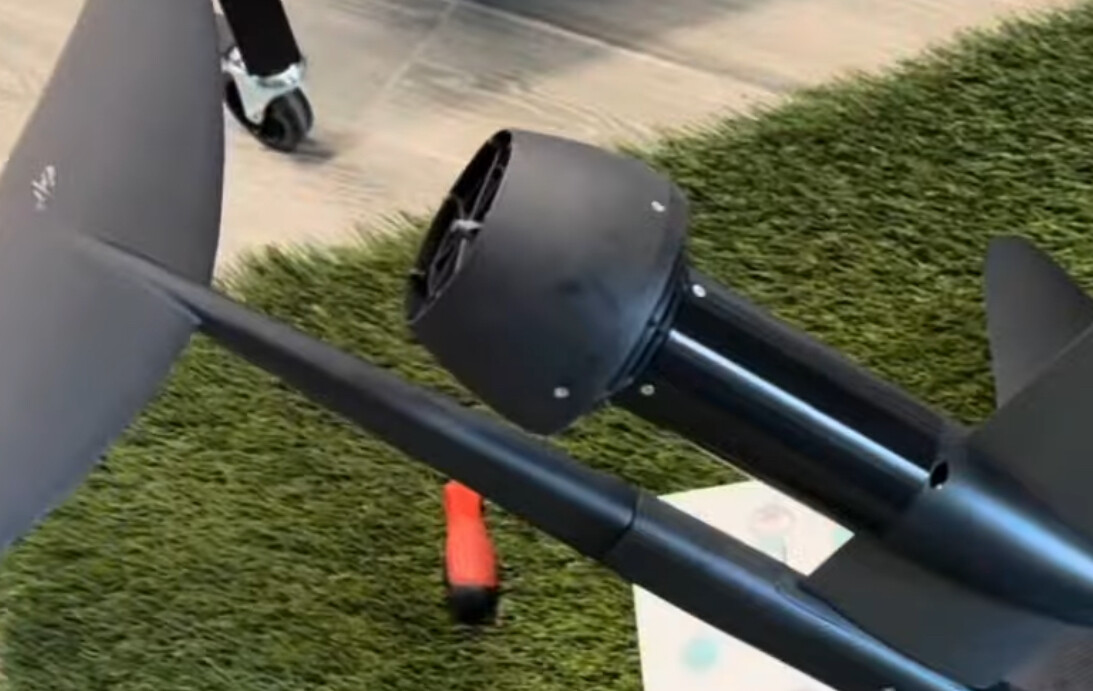
I’m trying to better understand the shape of the duct section where the water exits. Not that there is any need for modification although I will likely lose those 4 little retaining screws with my clumsy hands ![]()
In some camera angles there appears to be a small curved flare and in others it looks quite straight from the attachment end to the outlet. I’m also interested in the diameter of the outlet.
In this photo it looks “curved - flared”

In this photo is looks quite straight
Would the simplest solution not be to:
-
Machine out the part of the duct shown here so that it sits closer to the motor, and thus exposing more shaft.
-
Drill the 6mm hole in the prop to 8mm.
-
Mount the prop on the shaft and use a 8mm bolt on as standard.
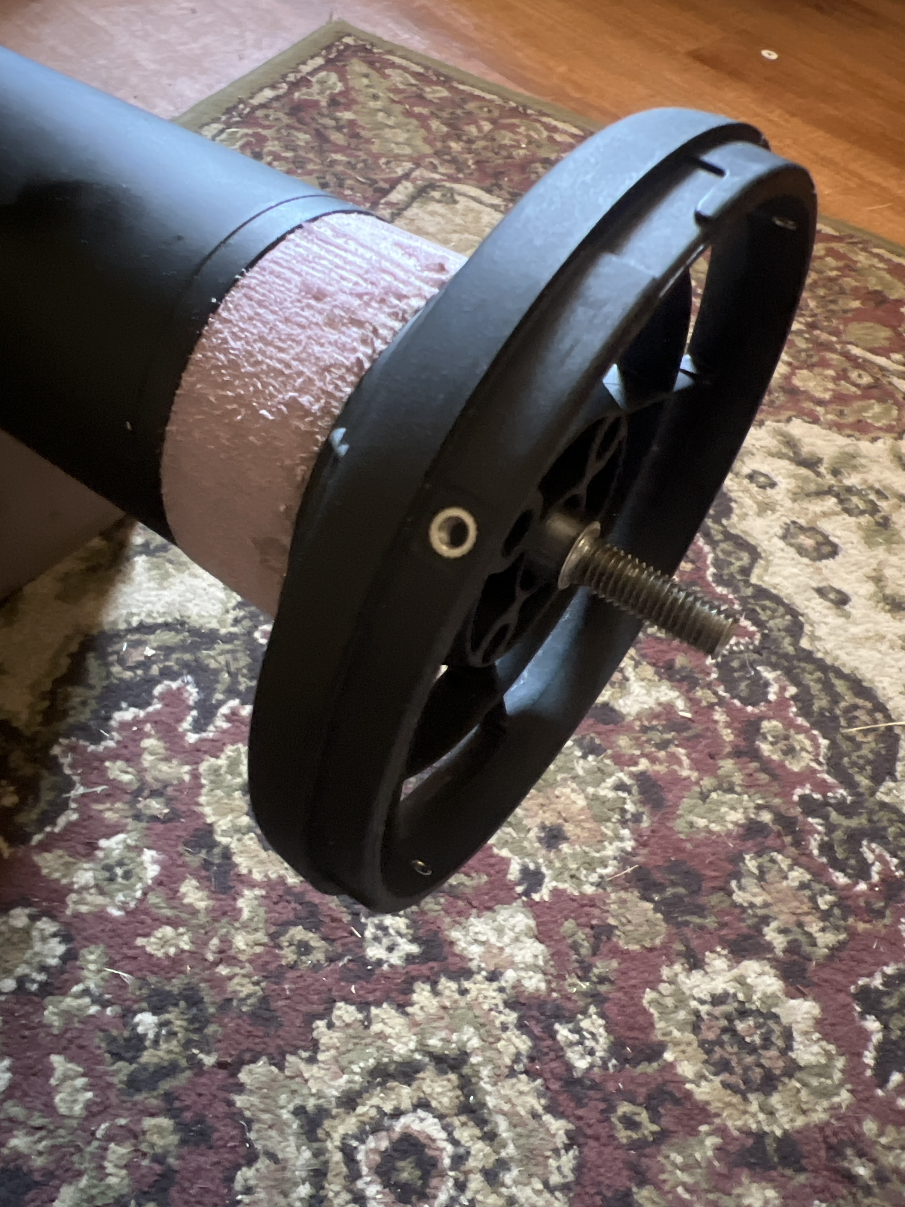
Just trying to follow along, you’re suggesting cutting into or boring out this surface that would normally be flush against the Lift motor? And this would allow a shorter spacer and more motor shaft to be available.
Correct. A stepped drill might work and would keep everything aligned.
By using a stepped drill bit like this. You don’t need to get it flush, just enough to expose the pin hold in the shaft.
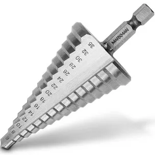
2 Likes
I have not used one of these but get the concept now. Thanks. ![]()
I’m not sure of what material the center of the duct is made of but I assume it’s stainless given the color and that’s what Lift chose for the center or the prop.
A quick web search reveals some of the stepped bits are titanium coated and others are high speed steel.
What material should the bit be to handle the stainless?
FYI @Foilguy, if you’re wanting to modify your own Lift Jet, Houston kiteboarding has them on sale: Lift Jet Efoil Propeller System - houstonkiteboarding
1 Like
The price on Lift’s site is $399 so I’m not sure where Houston gets the $566 starting point. Their reduced price is better though ![]()
Thanks for the lead!
I’m not sure of design/ engineering reason for the stainless insert, does it serve a purpose?
I would knock it out and then just drill the plastic. Drilling the stainless would most likely just cause it to spin anyway.
I’m not sure it is stainless - the why can only be answered by Lift and I doubt they would share.
Perhaps the forces on the aluminum were too great and the prototype cracked so they inserted a piece that wouldn’t. How’s that for a wild eyed guess from someone with little engineering skill? ![]()
It’s stainless and it’s moulded in because of the amount of pin exposed to it. It won’t spin if you drill it.
Does the pin rub on it ? Seems odd to have metal on metal.