Greate work!
I´ve also tried with this method for my kite hydrofoil wings. I copied the outline of Moses Onda 633 wings and designed it in F360. It was quite a challenge for me as this was one of my first work in a real CAD program. I did also some analysis in XFLR5 to test the airfoil and area of the wing.
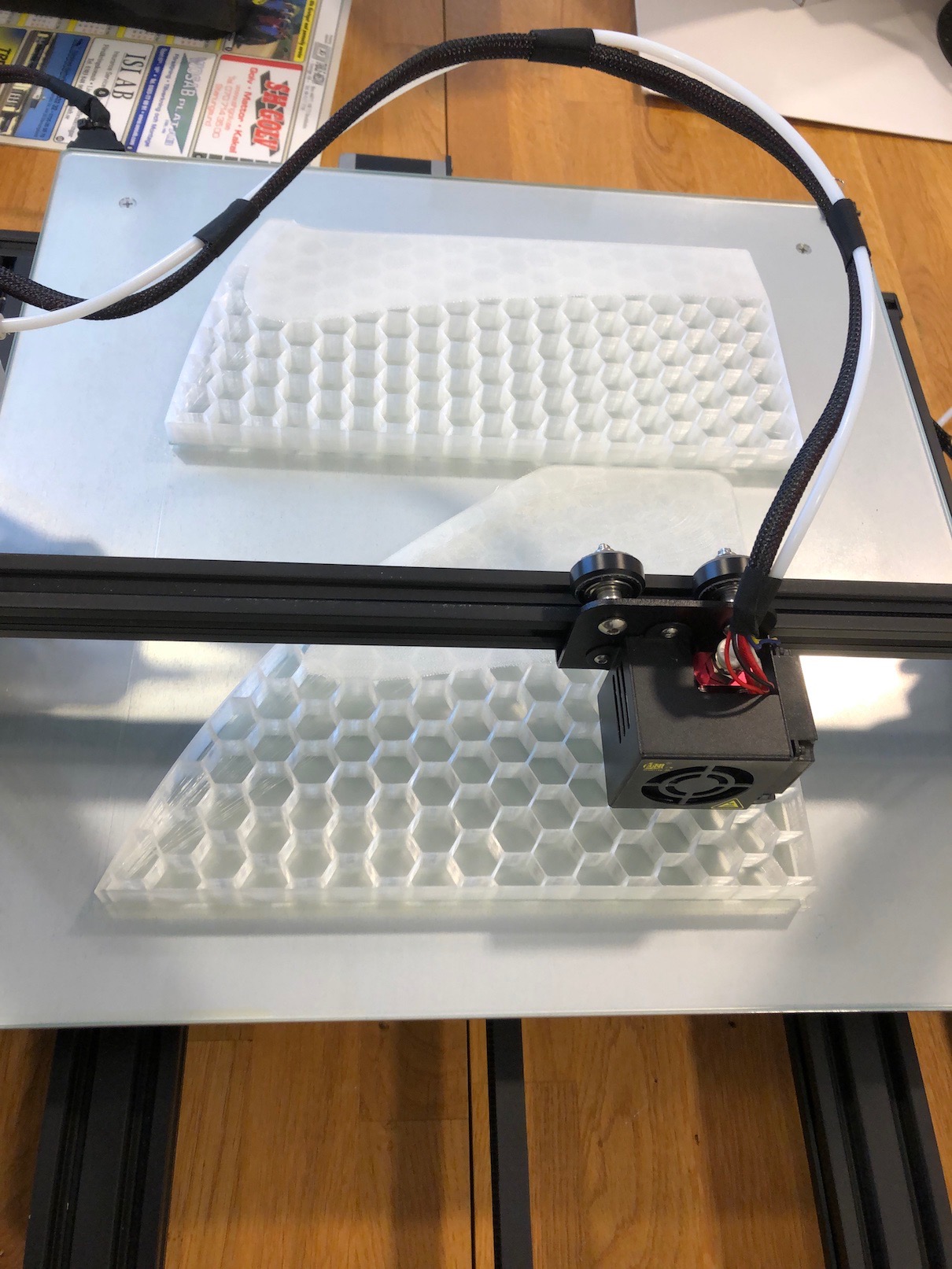
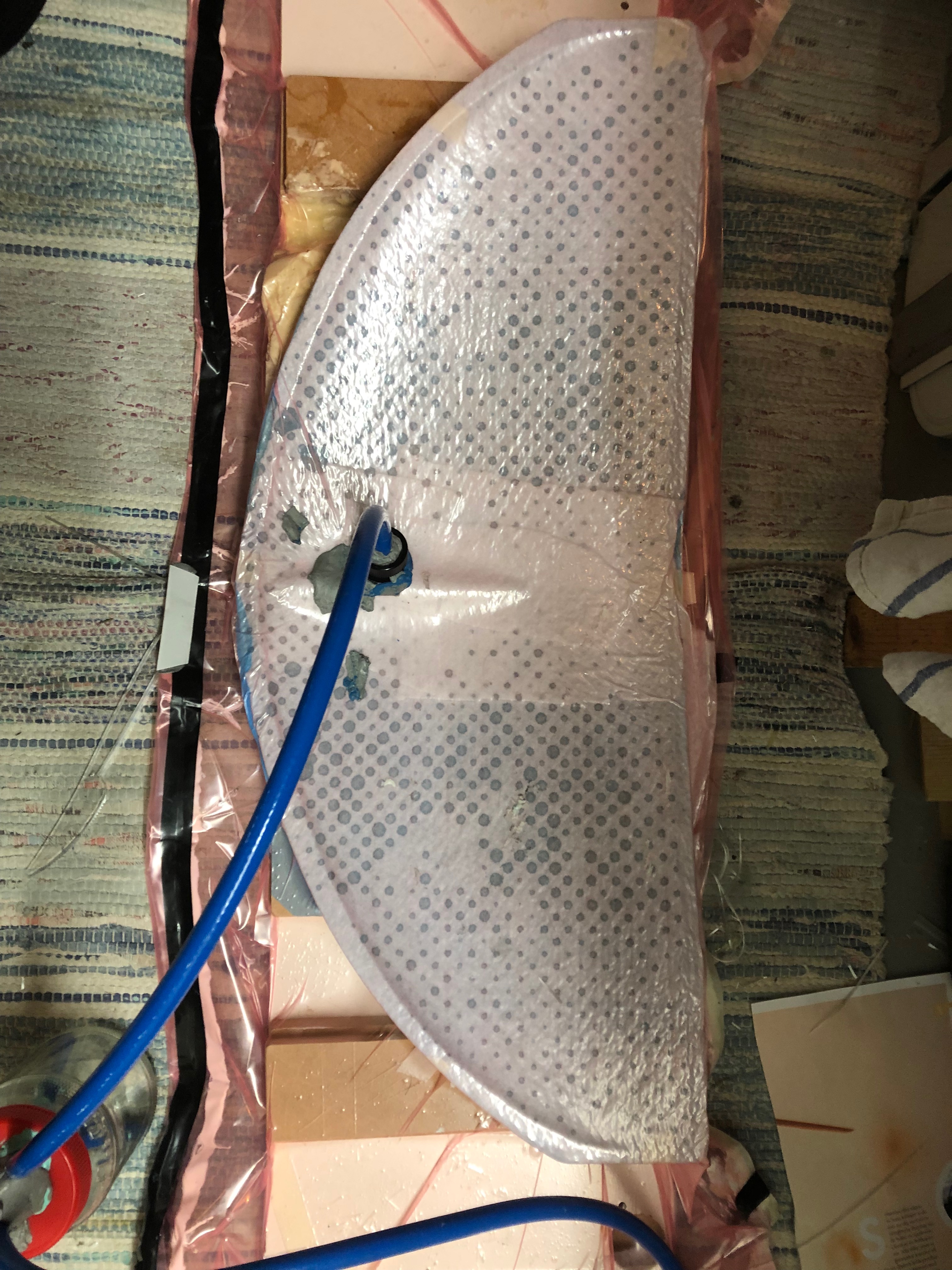
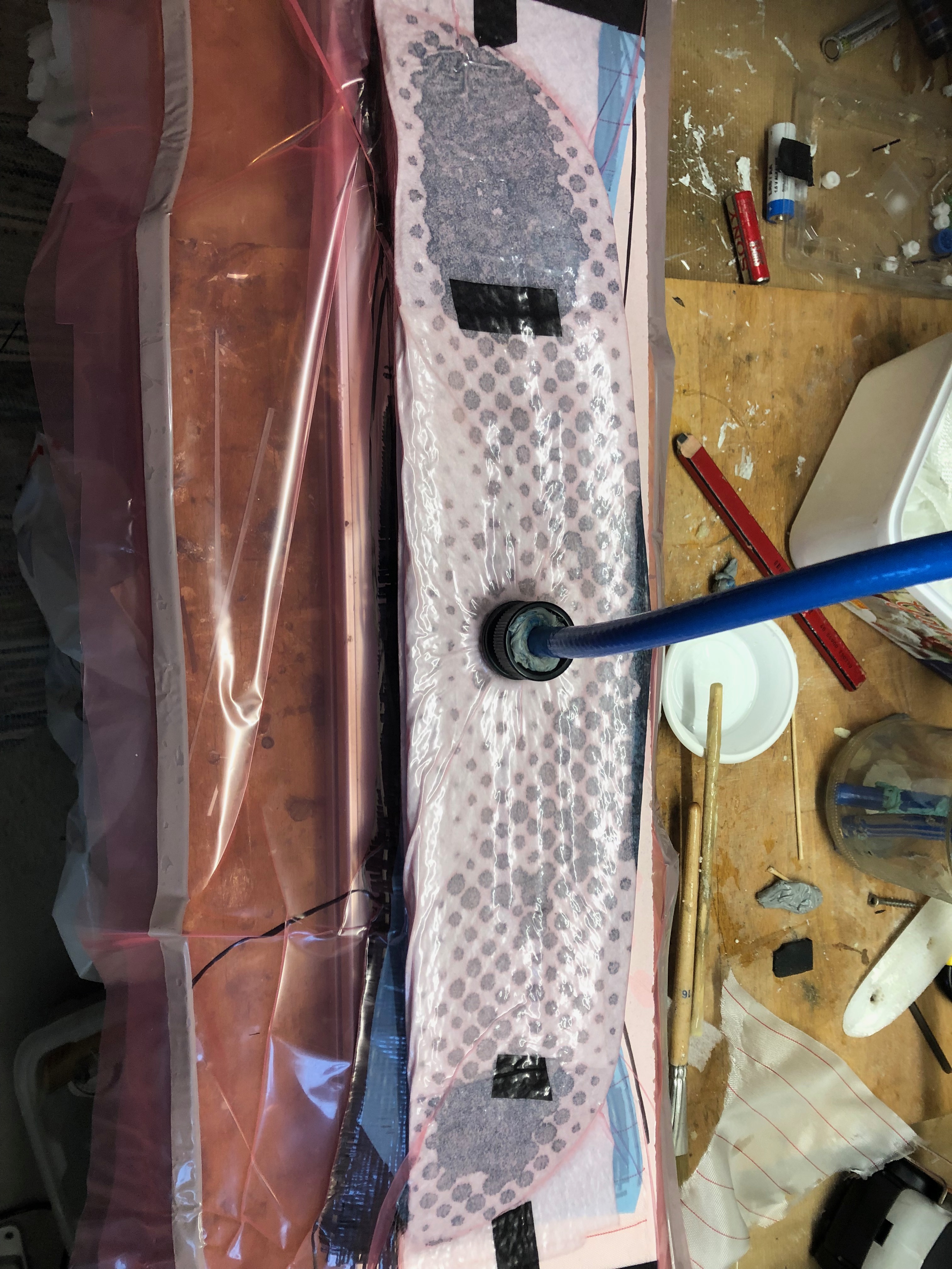
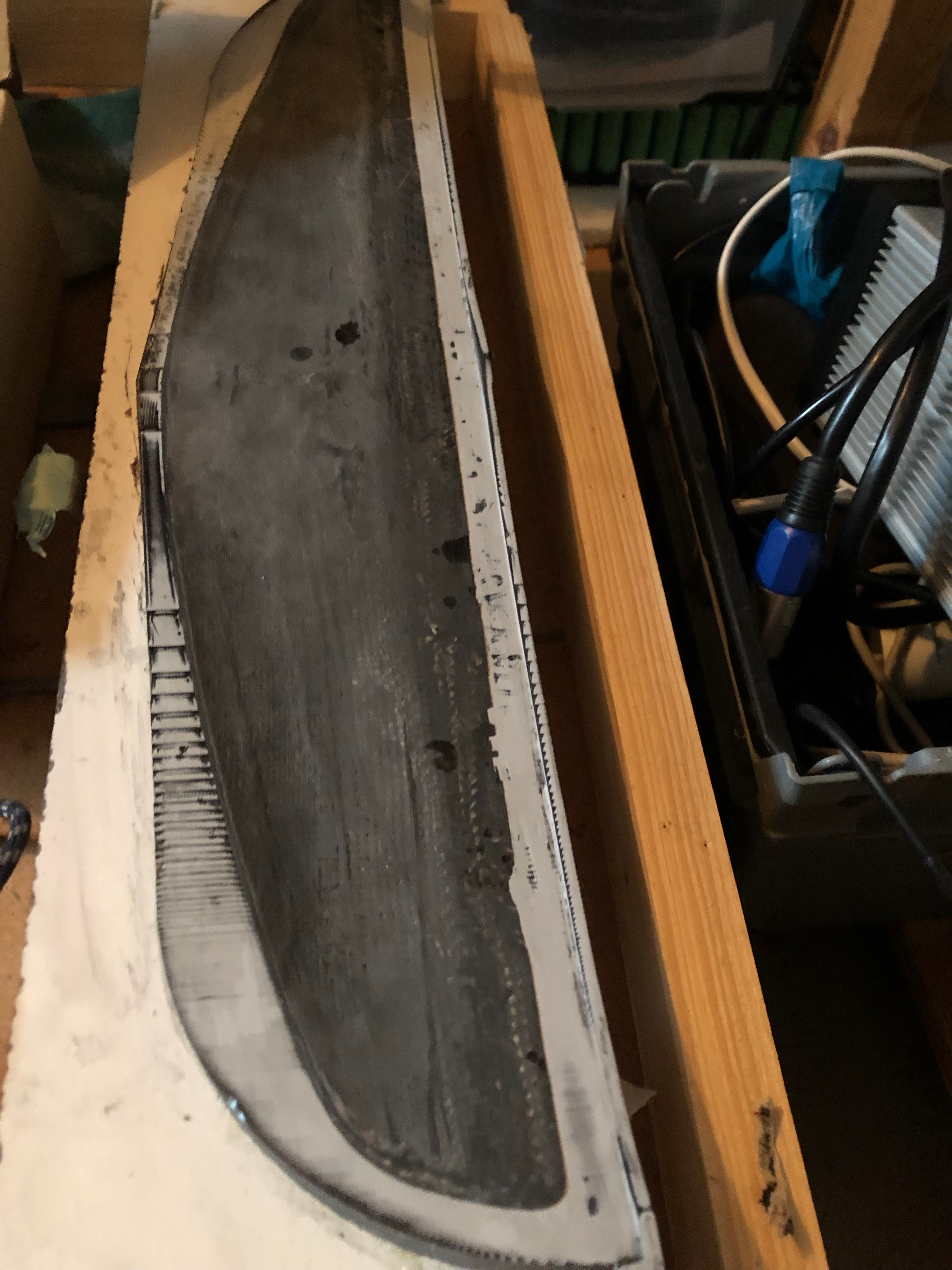
I printed mould of these wings splited in middle and I divided it in multiple parts that I glued together on a flat board. I used small woodparts as distance so I did´nt have to waste so much filament.
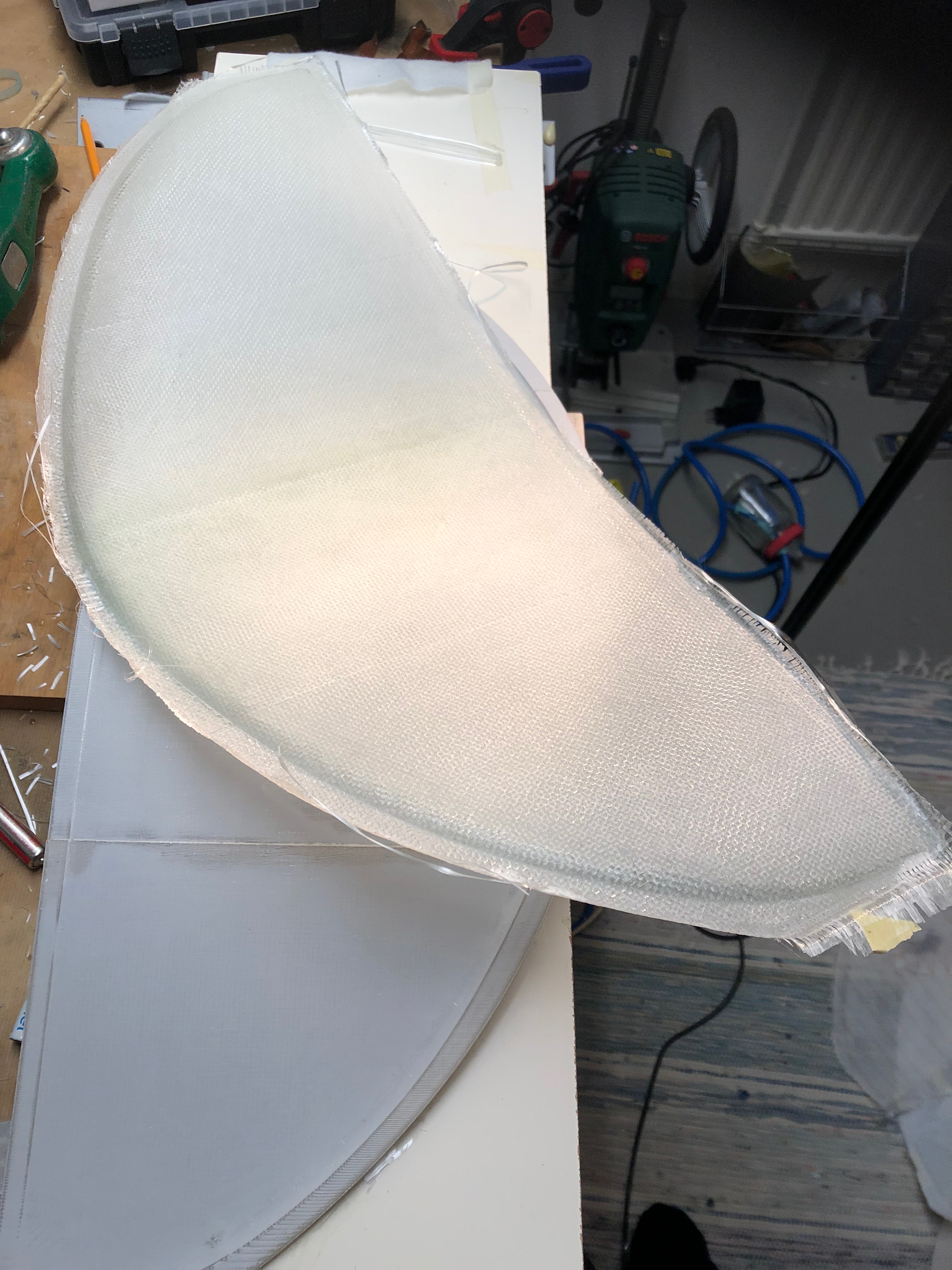
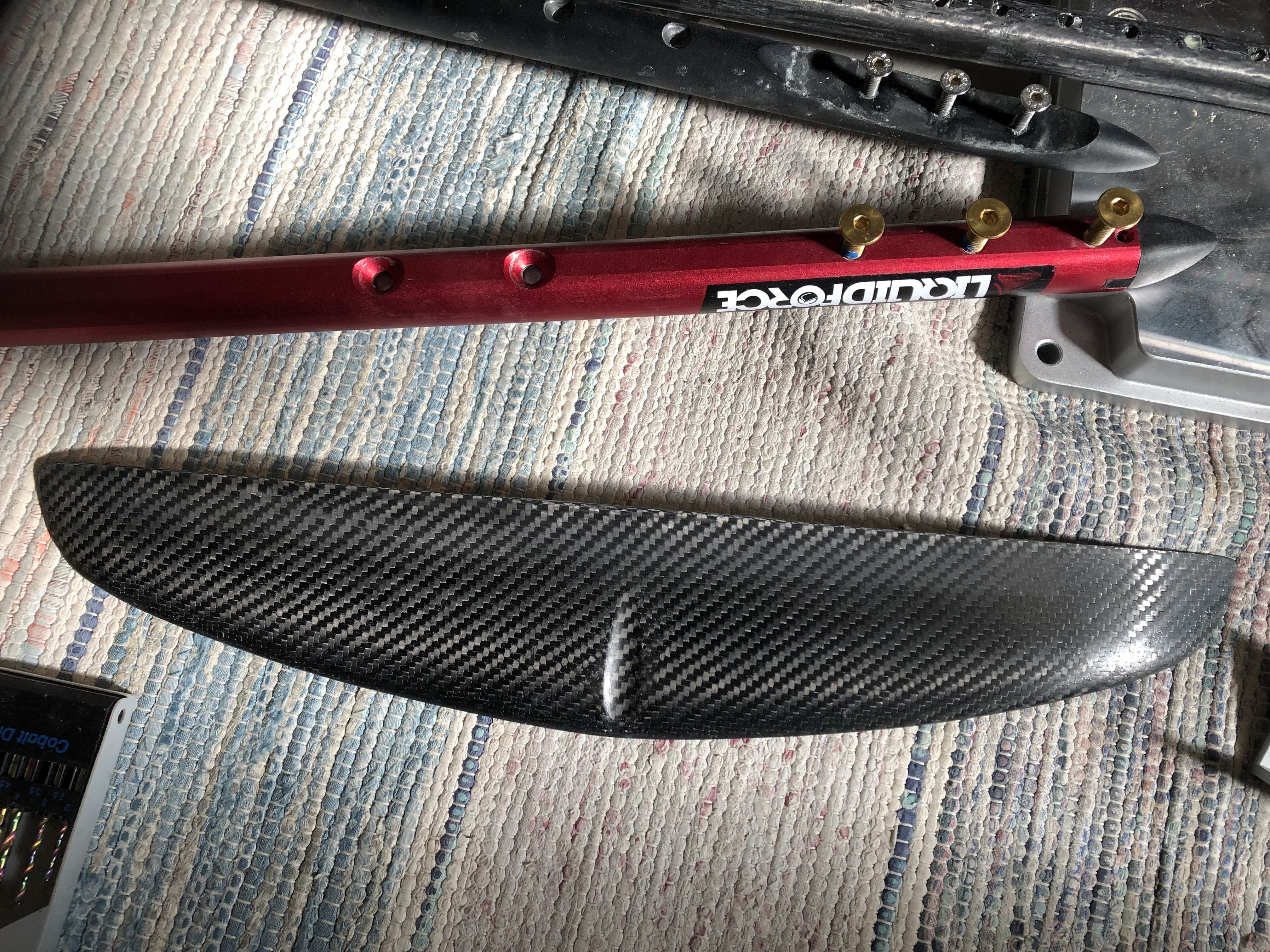
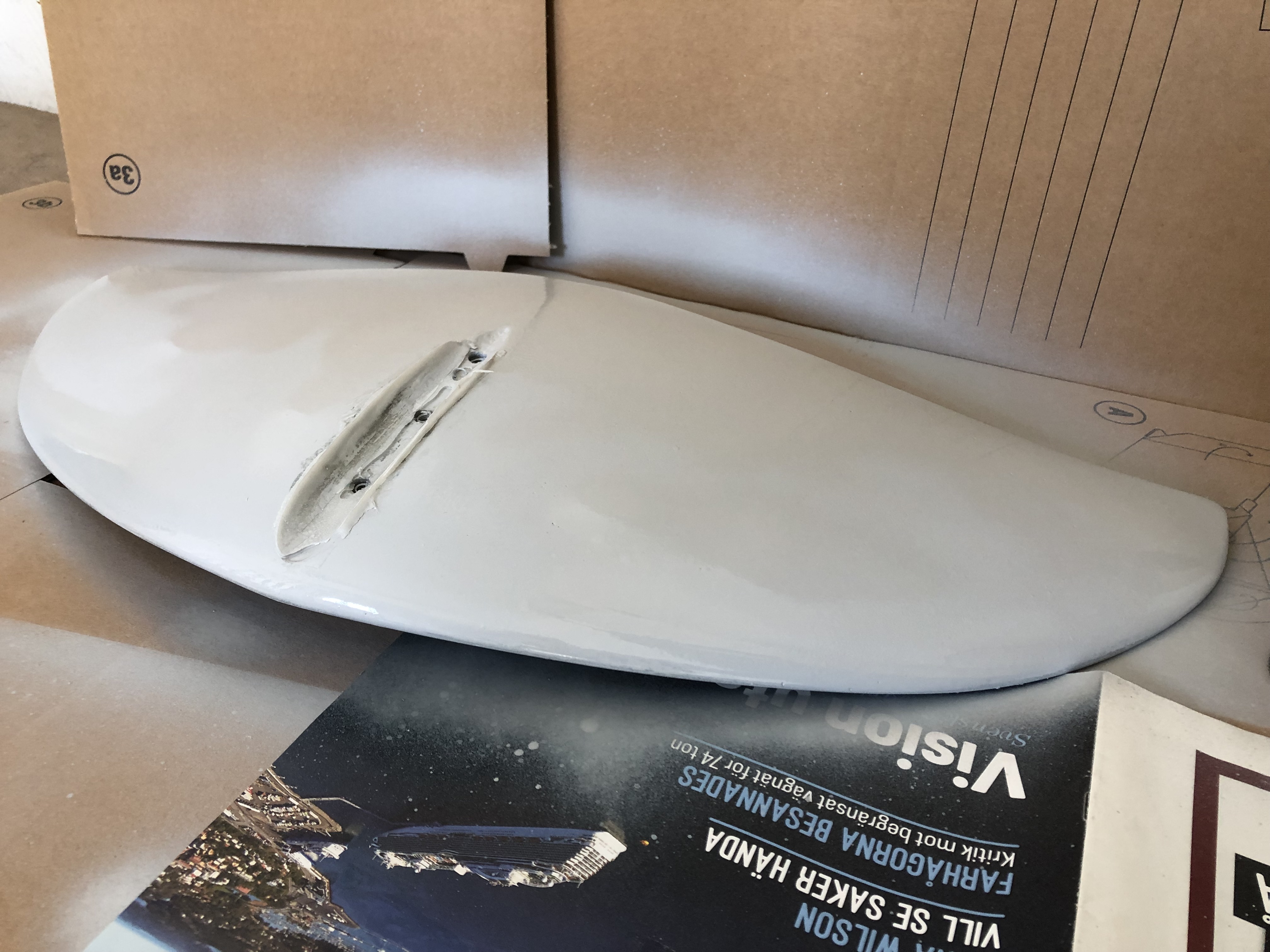
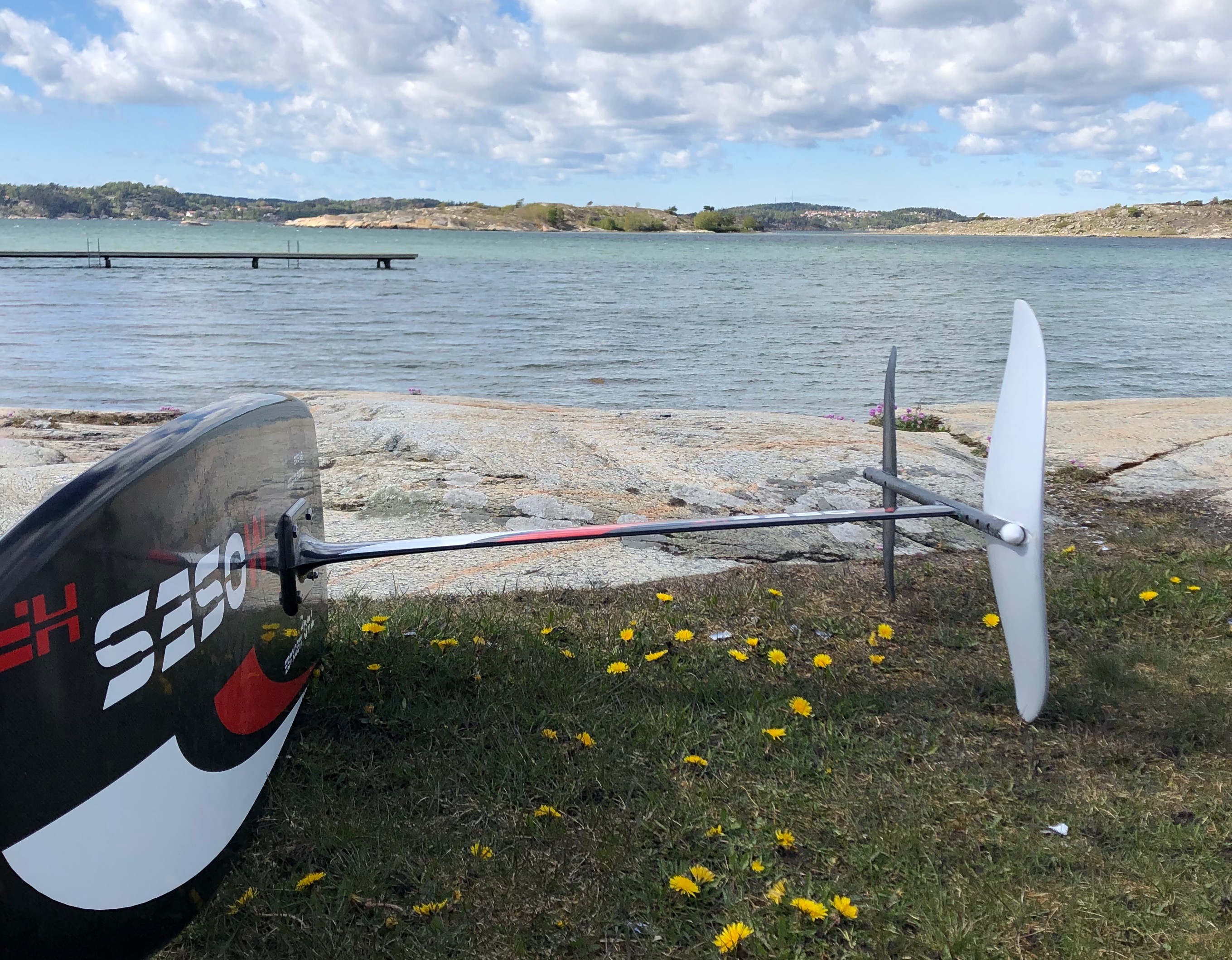
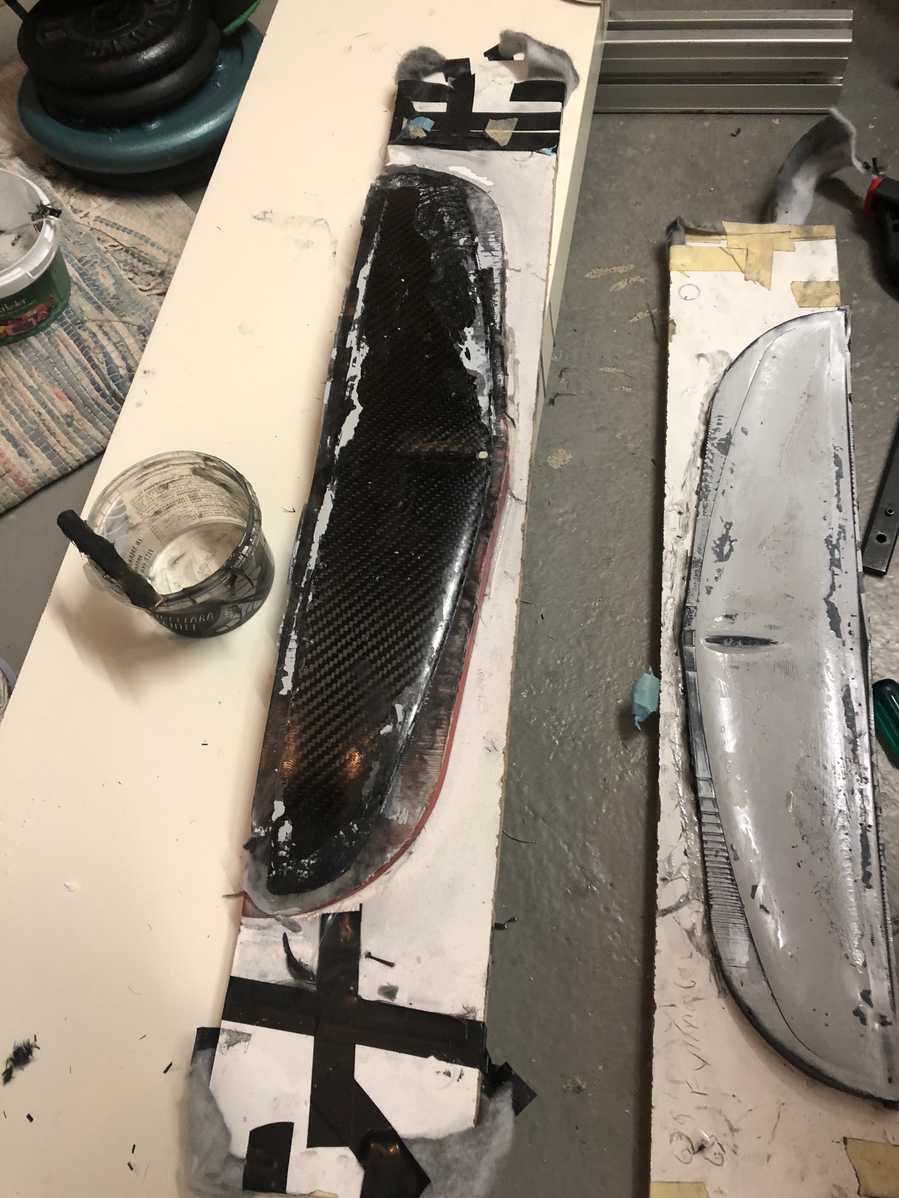
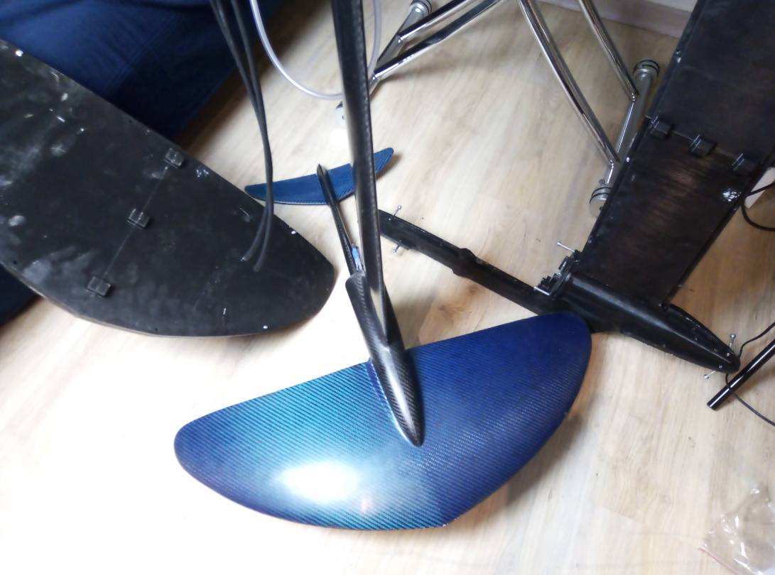
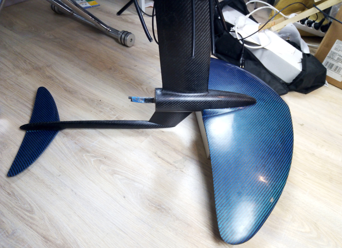
The mould was sanded and prepeared it with wax and release agent (PVA). I laminated the front wing with glas and the backwing with carbon as it so thin and its harder to get it stiff. I filled the front wing with hard polyuretan foam and the backwing with epoxy and carbonfiber flock. Then I joined them together using the mould to fixate them. The result is really good and the durability is also good. I´m jumping with it each session and there is no sign of damage. The only problem I had was when I got a little to aggressive in a rellay tight turn and ventilated half of the wing which got the 3 screws to bent and riped out from the wing. But because it is so light it also float and it was not hard to fix with some carbon fiber flock. My weight is 100kg so there was probably a lot of force only on one side of the wing.
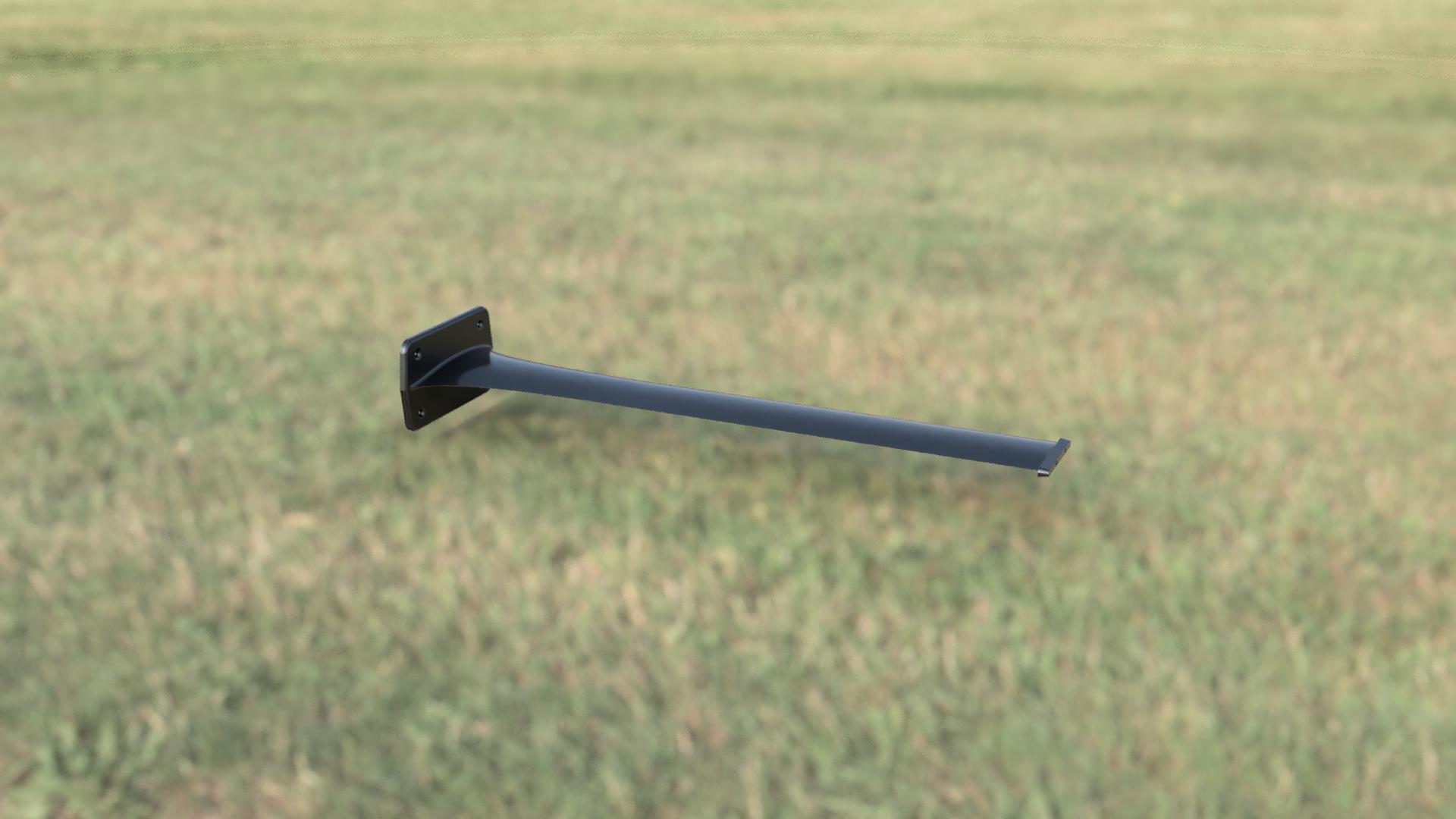
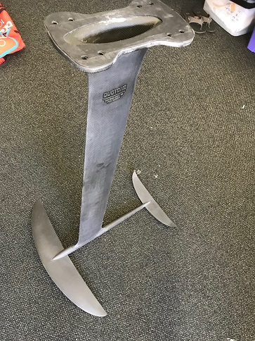
First I tried to make my own fuselage with a broken windsurfing carbon bom and some carbon battens from sails. It was hard to get it stiff in the joints between the mast so in the end I converted the wings to fit my Moses Vorace setup with alu-fuselage and carbon mast. I learned how big difference the shape of the FL has. The performance was so much better when I´ll switched to the Moses Vorace FL.
I´m really happy with these wings and specially now when I tested the “real” Moses Onda wings. I´ve used these wings for a year now mostly in waves and freestyle condition and switch over to a Banga foil when it´s time for racing. Those setups are really the opposite to each other.
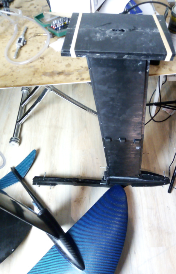
I´m gonna try these wings for my efoil as it is has early lift and easy to ride. It is much better then my Liquid Force foil that I´m using on my efoil today. So now I´m building a carbon mast with the same method. This mast will have a built in motormount and 3 glasfibertubes for the wires and one carbon tube for the cooling water. I will also try to fit a loadcell to measure the thrust.
Nice work ! With a wing that thick you can have enough stiffness from fiberglass for sure. You can use a thick biaxial cloth, it will give you more stiffness than woven fabric and cost a lot less than carbonfiber. I have also used this method of sanding + primer + pva at the begining, but this method have a lot of demoulding issues that I could not solve.
Yeah I also used biaxial cloth for the backwing but for the front wing I took regular glas in 45 deg patterns. One problem is the primer used on the mold to get good surface. Sometimes it stucks on the laminated wing. And also tricky to find the edge of the mold on the laminated pieces. Specially for the backwing. So this is something that i will try to do better on the next mold that I do.
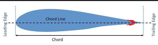
I use to have this problem, just add a small semicircle at the trailing edge (I would say at least 1-2mm in diameter) with the center of this semicercle at the chord line. Don’t make it too small because at the tip of the wing it will be even smaller and the 3d printer don’t have enough resolution to print it. Then it’s easy to find the edge
I think it will be much easier to 3d print if you turn the part at 90°. You will have more precision especially at the edges. Hope I helped you !
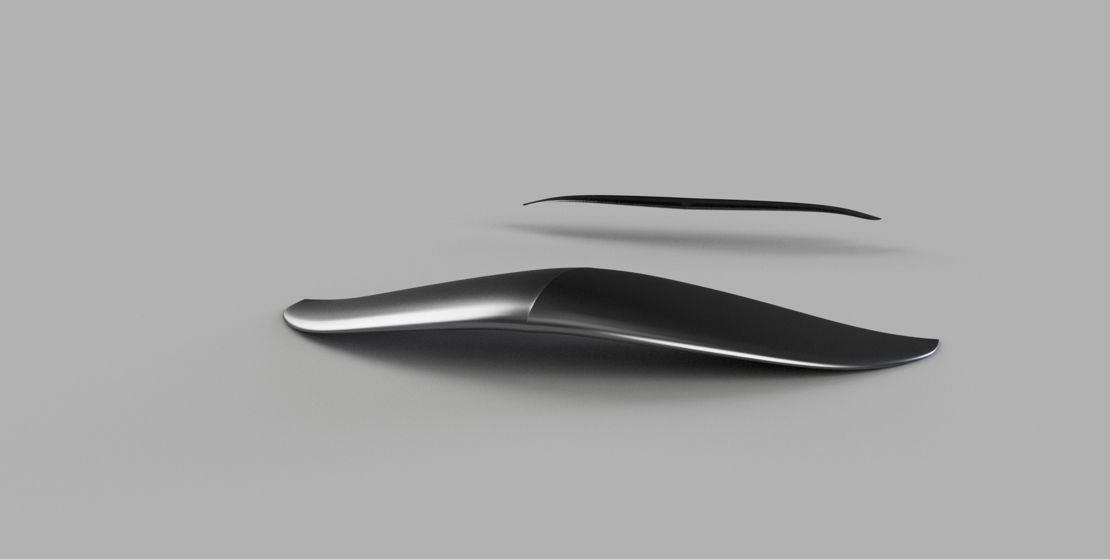
When you design the wing, you should add some curvature at the trailing edge so that you can see it on the mold (and the laminated part).
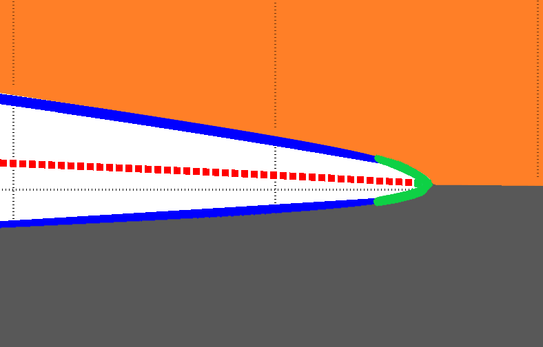
If we take a cross section of your mold (top side in orange and bottom side in grey) it should look like that (at the trailing edge). You can see that I added a curvature at the trailing edge of the wing (in green). It’s up to you to choose what curvature and thickness you want depending on the 3d printer resolution, how “sharp” you want it to be (for safety and performance), etc.
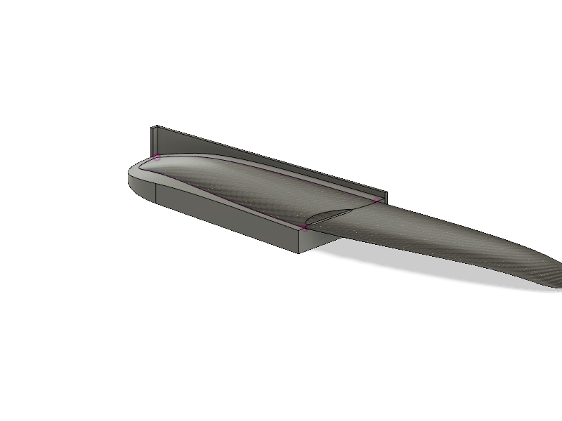
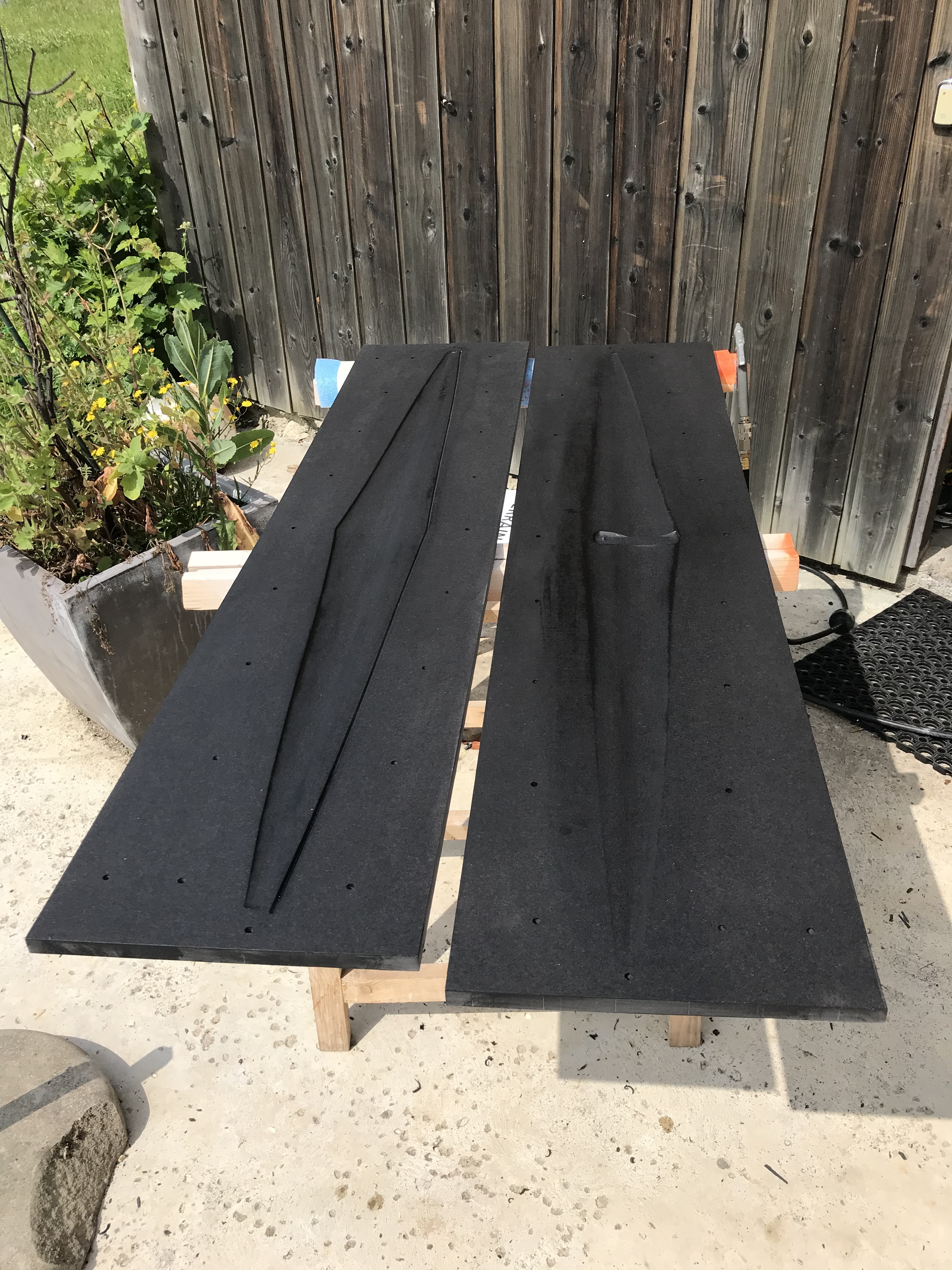
I did a small v along the trailing edge just out of the profile and on one side of the mold. That way your edge can be extremely thin and will « sing « less at high speed. After de-mold, just cut following the little v. Not easy to see on the photo, but one side of the mold you can see it.
Nice work on the wing mold Clarin ! what material and process did you use ? it looks like it was CNC machined on a wood board. For a 3d printed mold you can use a 0.25 mm radius on the trailing edge, and you should be able to see it depending on how you 3dprint the mold. It’s the thickness of a layer of carbon fiber or fiberglass (at around 200gr/m²), so I didn’t try to add a groove. It’s only about safety and perfomance I guess.
Yes I guess it should be possible, the only way to really know is to try. It could be too weak with this technique if you have only mechanical bond. My mast+fuselage isn’t hollow and the weight is about 2.6 kg. The height from the axis of the motor to the top of the mast is 75 cm (and the total length top to bottom is around 90 cm). You can pass the cables through 3 tubes inside the mast. Why do you want to put the connectors inside the mast ?
That is a good question: saving some room in the compartment, simplicity, extra level of waterproofness if the cables are sealed (silicon ?) at board bottom level with hanging connectors. Maybe forum users out there could see other reasons…
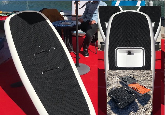
I’m not sure because if the area between the board and the mast is not sealed properly you will have water inside the mast ! The way I designed the board is one fully sealed box with all the electronics and the battery (under the board for safety) and a small “connection” box on the top of the board to charge the battery, etc.
I did that because I don’t plan to change the battery and to reduce cost. If you want to have a hatch and change the battery you need to make everything fully water proof (including the battery).
We could also imagine everything but the battery inside the top part of mast (mini ESC like the @nickw1881 one (106 x 54 x 26 mm) , radio, possibly with a no-pump but short water cooling loop ala LIFT/Flying Rodeo) … just saying.
Then, a DiYer would just need to concentrate on a small battery case like Sailfin Plurato does…
That would also mean only two XT connectors between board and mast.
Can anyone pitch in how many layers of carbon would be required to get this working? It’s easy enough to do with a xps foam core that you can melt away with acetone after laminating or using a core that you pull out afterwards (like filament winding mandrels) just needs a taper to it which is easy enough. I like the idea since you can machine an aluminium case for the ESC that is waterproof and have the esc in the strut. Carbon doesn’t have the best heat transfer coefficient but one could use the strut as a heatsink.
For maintenance purpose, I was thinking about an extractible ESC on rail with case as computer hard drives… … a rack connection style, no wire connected to ESC but 3 between lower part of ESC outer case and motor
Totally possible. That apd esc I will be using is compact enough to fit in the top of the strut just needs a casing around it that follows the inside of the strut.
I would be interested in trying it out. Just not sure about the laminate buildup.
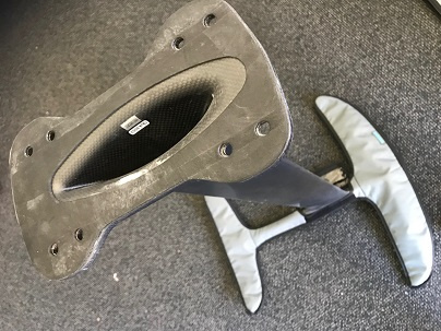
Hi guys ! I have been working hard the past 3 months sorry I didn’t post anything. But I think you will like the result (I hope haha). I have redesigned the fuselage&mast and the front wing. I also improved a lot the process of making 3d printed molds. It’s much cheaper now with better result!
Outstanding finish quality. Looking forward to the first water tests and more information about how you achieve such results.
Do you vacuum ?
Mold life cycle: how many pieces per mold can you achieve while maintaining a good quality ?