That is a good question: saving some room in the compartment, simplicity, extra level of waterproofness if the cables are sealed (silicon ?) at board bottom level with hanging connectors. Maybe forum users out there could see other reasons…
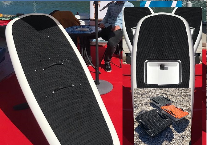
I’m not sure because if the area between the board and the mast is not sealed properly you will have water inside the mast ! The way I designed the board is one fully sealed box with all the electronics and the battery (under the board for safety) and a small “connection” box on the top of the board to charge the battery, etc.
I did that because I don’t plan to change the battery and to reduce cost. If you want to have a hatch and change the battery you need to make everything fully water proof (including the battery).
We could also imagine everything but the battery inside the top part of mast (mini ESC like the @nickw1881 one (106 x 54 x 26 mm) , radio, possibly with a no-pump but short water cooling loop ala LIFT/Flying Rodeo) … just saying.
Then, a DiYer would just need to concentrate on a small battery case like Sailfin Plurato does…
That would also mean only two XT connectors between board and mast. ![]()
Can anyone pitch in how many layers of carbon would be required to get this working? It’s easy enough to do with a xps foam core that you can melt away with acetone after laminating or using a core that you pull out afterwards (like filament winding mandrels) just needs a taper to it which is easy enough. I like the idea since you can machine an aluminium case for the ESC that is waterproof and have the esc in the strut. Carbon doesn’t have the best heat transfer coefficient but one could use the strut as a heatsink.
For maintenance purpose, I was thinking about an extractible ESC on rail with case as computer hard drives… … a rack connection style, no wire connected to ESC but 3 between lower part of ESC outer case and motor
Totally possible. That apd esc I will be using is compact enough to fit in the top of the strut just needs a casing around it that follows the inside of the strut.
I would be interested in trying it out. Just not sure about the laminate buildup.
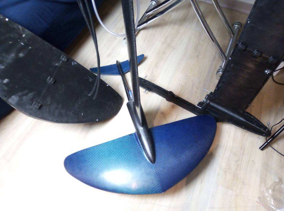
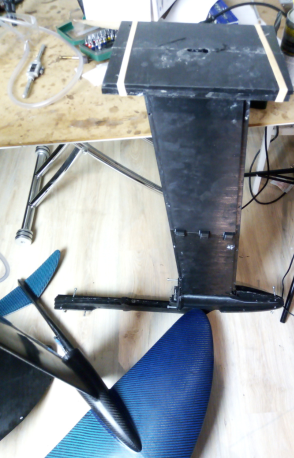
Hi guys ! I have been working hard the past 3 months sorry I didn’t post anything. But I think you will like the result (I hope haha). I have redesigned the fuselage&mast and the front wing. I also improved a lot the process of making 3d printed molds. It’s much cheaper now with better result!
10 Likes
Nice work, I love it 
Is the mast also full carbon fiber ?
1 Like
Outstanding finish quality. Looking forward to the first water tests and more information about how you achieve such results.
Do you vacuum ?
Mold life cycle: how many pieces per mold can you achieve while maintaining a good quality ?
1 Like
Thanks man! Yeah it’s full carbon, and filled with a carbon fiber filler (I prefer safety). But you can make it hollow too.
you can find more details here https://www.easy3dcomposites.com/pages/efoil and here you can see the preview video https://www.easy3dcomposites.com/products/efoil
My website isn’t finished so there are maybe bugs in some pages… (it doesnt work well with internet explorer) My goal is to make everything free for efoil builders if they post a positive review and a picture to help me with the website (and I reduced all the prices by half during this time). I will help them with their build. Find solutions to their problems and share with everybody.
4 Likes
Yeah in the beginner course I show how I make a cheap (less than 100$) and user friendly vaccum bagging system easy3dcomposites.com Because standard vacuum bagging system can be super expensive and not easy to use… You will find all the info to make reusable 3d printed molds in the beginner course and like I said if you post a positive review with pictures I will give a full refund so it’s actually free.
Mold life cycle will depend on so many things : how well you build your mold, how “aggressive” the resin you use is, if you use the mold properly, etc. If you do 0 “maintenance” (cleaning the mold, good storage, applying some layers of release agent after each “pull”, etc.), the lifecycle will be much shorter. I haven’t done destructive tests yet (to see the maximum parts we can make)
I only used the same mold 5 times. And the surface still looks great, it didn’t feel more difficult to remove the part from the mold. So I believe you can make a lot of parts from these molds if you use it properly.
1 Like
Good deal… will buy it. Hope it will save lot of my time…
1 Like
Hello
I have it do and with paypal buyed. Where found i the STL ?
i will test it 
Greetings frank
Hi there. I’ve paid and downloaded and watched and read everything. Thanks a lot for making it available. I’m wondering if you or anyone else can share some insight into the performance of this set up. Both Delta and High Aspect wings too if possible! Cheers
1 Like
It takes me a few more days …
Greetings Frank
Hi Mattygsa!
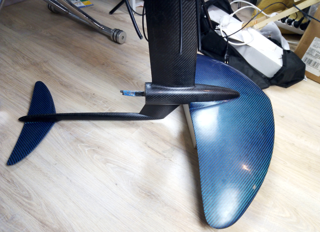
The performance will depend a lot on how you build each parts (flexibility, porosity on the surface, thickness of the trailing edge, etc.). Also If the mold is not properly done or if you crush it during the laminating process (because of pressure and/or heat), the final part will have a different geometry. But you can expect more lift (and more drag) from the delta wing. It will be also more maneuverable than the high aspect ratio wing. The high aspect ratio wing should be more efficient (but maybe not the best for beginners). the delta wing has a surface of around 1600cm² and the high aspect ratio wing 1050cm².
2 Likes
That looks very nice
1 Like
Thanks!
I’m working on a different way of making the wing using 3d printed honeycomb structure. It will increase stiffness and reduce the weight. It’s better for people who wants to make the wings from fiberglass to keep the cost very low (if you use carbon fiber you will have a lot of stiffness without the honeycomb structure)
Our efoils can be qualified as “Low Reynolds” because they mostly work at speeds less than 500.000 Re numbers.
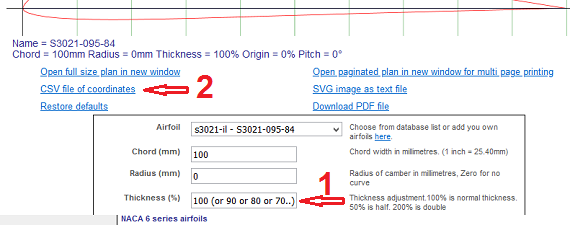
Here are a few “flat bottomed” candidates with a fast/low drag/pitch tolerant reputation that can be slimmed down in the Airfoill Plotter section of Airfoiltools.com . For example, let’s consider a S3021 section whose initial thickness to chord ratio (TR) is 9.5%. If you write 84 in the “Thickness” field, the resulting section will be thinned down to 9.5 x .84 = 8% which is the TR of a fast and still tolerant wing.
1 - get the .dat file data in the S3021 “Detail page” S3021-095-84 (s3021-il)
2 - click on “Send to airfoil plotter” to play with the thickness Airfoil plotter (s3021-il) and download the .csv file to import into your 3D design SW (F360, SW, …)
A big advantage for mold making: the lower section (intrados) is flat or nearly flat:
Airfoil section name and TR (%) - ( R/C Soaring world comment)
S7055 10.5% S7055 (10.5%) Flat-Bottomed (s7055-il) (“doesn’t build up speed too quickly”)
S3021 9.5% Airfoil plotter (s3021-il) (“builds up speed quickly”)
E205 xxxx (“builds up speed quickly”)
RG 15…
CLARK Y…
CLARK W…
To be cont’d …
2 Likes