Hello
I have it do and with paypal buyed. Where found i the STL ?
i will test it 
Greetings frank
Hi there. I’ve paid and downloaded and watched and read everything. Thanks a lot for making it available. I’m wondering if you or anyone else can share some insight into the performance of this set up. Both Delta and High Aspect wings too if possible! Cheers
1 Like
It takes me a few more days …
Greetings Frank
Hi Mattygsa!
The performance will depend a lot on how you build each parts (flexibility, porosity on the surface, thickness of the trailing edge, etc.). Also If the mold is not properly done or if you crush it during the laminating process (because of pressure and/or heat), the final part will have a different geometry. But you can expect more lift (and more drag) from the delta wing. It will be also more maneuverable than the high aspect ratio wing. The high aspect ratio wing should be more efficient (but maybe not the best for beginners). the delta wing has a surface of around 1600cm² and the high aspect ratio wing 1050cm².
2 Likes
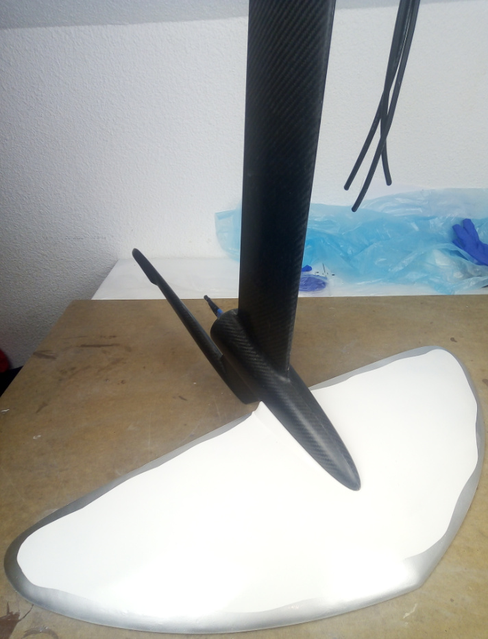
That looks very nice
1 Like
Thanks!
I’m working on a different way of making the wing using 3d printed honeycomb structure. It will increase stiffness and reduce the weight. It’s better for people who wants to make the wings from fiberglass to keep the cost very low (if you use carbon fiber you will have a lot of stiffness without the honeycomb structure)
Our efoils can be qualified as “Low Reynolds” because they mostly work at speeds less than 500.000 Re numbers.
Here are a few “flat bottomed” candidates with a fast/low drag/pitch tolerant reputation that can be slimmed down in the Airfoill Plotter section of Airfoiltools.com . For example, let’s consider a S3021 section whose initial thickness to chord ratio (TR) is 9.5%. If you write 84 in the “Thickness” field, the resulting section will be thinned down to 9.5 x .84 = 8% which is the TR of a fast and still tolerant wing.
1 - get the .dat file data in the S3021 “Detail page” S3021-095-84 (s3021-il)
2 - click on “Send to airfoil plotter” to play with the thickness Airfoil plotter (s3021-il) and download the .csv file to import into your 3D design SW (F360, SW, …)
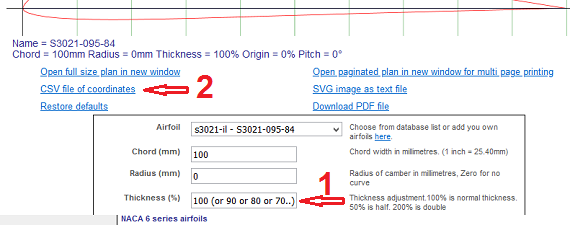
A big advantage for mold making: the lower section (intrados) is flat or nearly flat:
Airfoil section name and TR (%) - ( R/C Soaring world comment)
S7055 10.5% S7055 (10.5%) Flat-Bottomed (s7055-il) (“doesn’t build up speed too quickly”)
S3021 9.5% Airfoil plotter (s3021-il) (“builds up speed quickly”)
E205 xxxx (“builds up speed quickly”)
RG 15…
CLARK Y…
CLARK W…
To be cont’d …
2 Likes
So a flat bottom wing tend to better for hydrofoils ? I’ll do more research and try to make better wings! You could run into some problems if you import the CSV file but it will be more precise for sure. You can use splines and try to be as precise as possible (don’t expect too much precision from the 3d printer anyway).
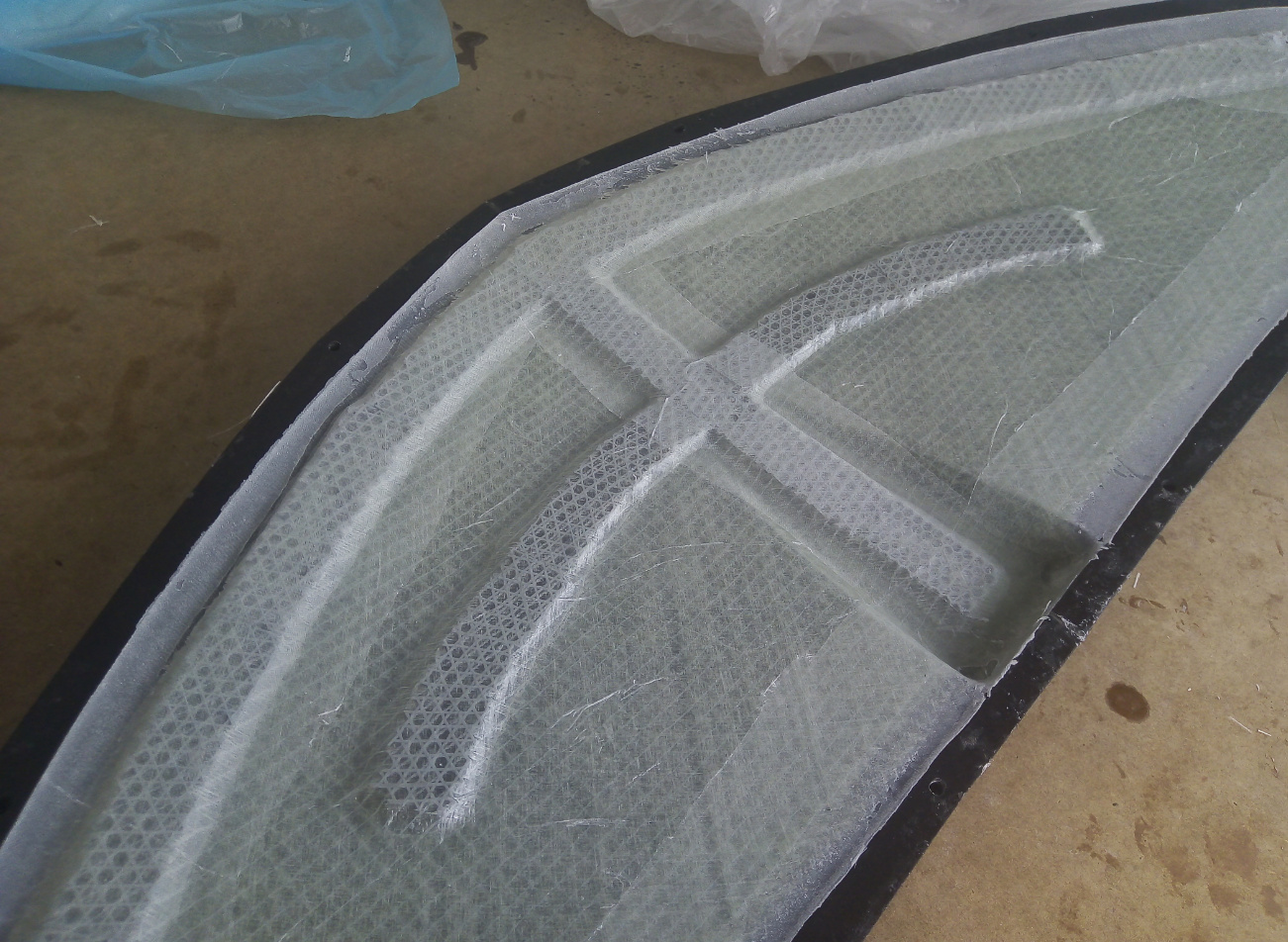
I tried to use 3d printed honeycomb material on this fiberglass wing. It definitely increased stiffness! The joining process is different and stronger too so the wing is lighter (it weighs about 930 grams so you save about 250 grams - 300 grams of weight).
Not sure about the painting tho lol maybe I should make it black and white or just plain white.
Adding the honeycomb structure helps a lot for fiberglass wings (I removed one backing layer of fiberglass because it already had enough strength).
3 Likes
The files are update! I guess you could use a similar method to make the fuselage&mast hollow but I would not recommend it (better to make a mast as strong as possible to make it as safe as possible). Also this wing cost almost nothing to build (around 25$) because the same materials are being used. I will try to improve the method for the mast&fuselage too (to make it stronger, lighter and also easier to build).
The more a profile is curved, the more it translates small variations of AoA into strong lift changes. Therefore many brands choose to have low to zero curve to have a more controllable foil that doesn’t breach the surface too easily at high speed because breaching often means falling.
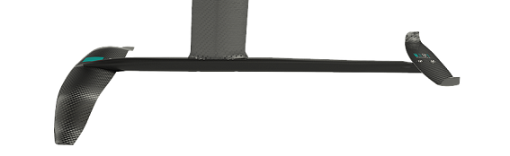
A friend told me that the Taaroa Noe 2020, a high AR freerace windfoil, uses the S7055 airfoil section or something very similar.
Manufacturer description:
A extremely rigid and stable foil optimized for power and speed. For riders who look for performance with serenity.
a little bit of topic, but still 3D and CF related.
I’m thinking of 3D printing some parts for my jet board (with PLA), and I would like to “wrap/cover” them with CF (maybe 2 layers?)
Question. Does CF when curing get hot, and will it destroy the 3D PLA created shape?
Thank you for any info on this.
It’s no Problem with Epoxy.
Greetings Frank
Yes that’s right, you will get more difference of lift for the same variation of angle of attack. I analyzed 3 profiles (RG15, E817 and AQUILA 9.3%). I preferred to choose known profiles that have already been used. I wanted to create a wing that can provide enough lift at low speed (and at a “higher” angle of attack), but also to be able to go faster if we want to (at low angle of attack). The AQUILA 9.3% is great too (very similar to the S7055) but I couldn’t find a better wing shape (delta shaped) with a good AR and surface area that creates enough lift at low speed (and higher AoA) and not too much lift at higher speed and low AoA (to go faster).
But I was planning to test each wing myself to be 100% sure even if any wing works. It would be nice to optimize it to make nice and easy to use.
If it’s only 2 layers the epoxy will not release enough heat to soften the 3d printed part. If you try to make a super thick (+5mm) part at once (and you use a fast hardener) then yes it will be most likely too hot . Do you know which CF cloth you will use ?
1 Like
I am thinking of using 245 g/m² CF cloth (link to Dutch website: https://bit.ly/3i7LQKD )
Thickness 0,393 mm
What about 90 degree corners? Will this work, or do the corners need to be rounded (like for glass fiber)?
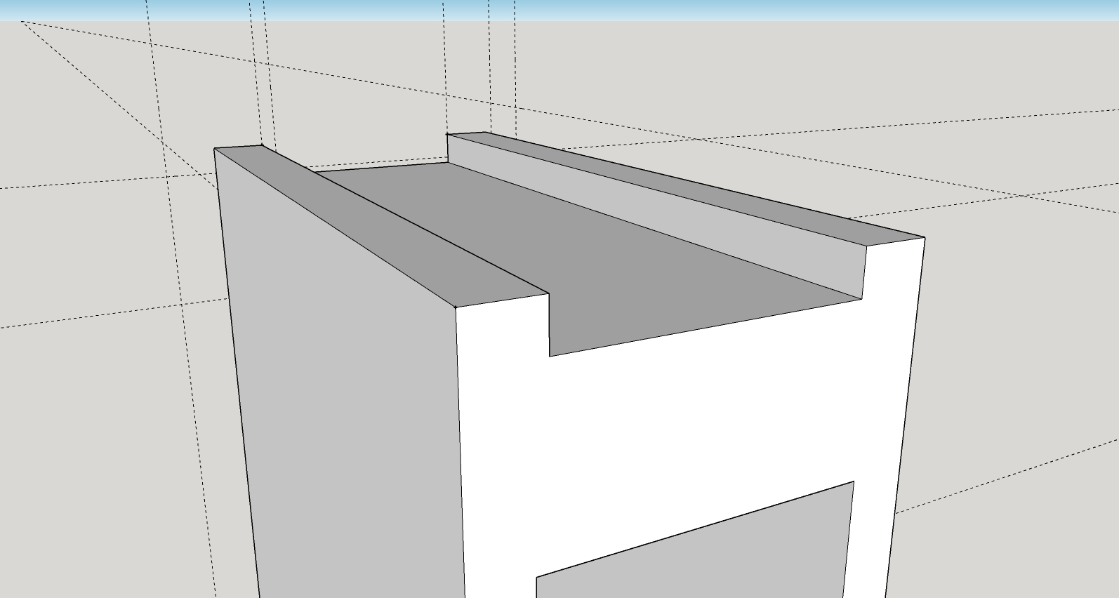
The rubber gasket groove will be 3 mm deep and 90 degree corners at the top of the groove.
I will be using a vacuum bag!
If you want the CF cloth to be in contact against the surface then yes it needs to be rounded. Usually you need at least a minimum of 3mm (or 1/8’’) corner radius. The part seems very small, you may have a hard time warping it with CF!
Yes this part is small. It is for the rubber sealing (gasket).
I’m going to leave it as is (PLA), and maybe just put some hardener on it.
Anyway. Thank you for the information. I’m 3D printing the needed parts now. It’s going to take a long time…
1 Like
Hi I have problems with the operation to access the course. The link is corrupt
https://easy3dcomposites.thinkific.com/users/sign_in

I tried to open a helpdesk, I wanted to find out if any of you have the same problem.
Could you give me a hand to unlock it?
Thank you