awesome mate! what about this one?!
Not at the city but Very near St André de cubzac N10 direction Angoulême 
i ride a home (private lake ) or in local river or at sanguinet lake (no salt water ) we rent boat in summer at sanguinet marine🤙 maybe ready for the océan with salt water the next year because i Never pratice foil before efoil like you ,and i think i needed pratice befor erinding thé waves😆
1 Like
I’m in Bassens! !!!
Carement pas loin cool …si un weekend ou il fait beau tu veut venir voir comment sa ce passe j’aurai pas mal de conseil à te donner en direct Live hésite pas en mp pour pas pourire ton fil 
2 Likes
Guys, I’m moving. I’ve ordered the P42 cells 
I need now to decide on the ESC, remote & props !
1 Like
Or the Gong carbon Tbar with 150kg high density PU foam core to be drilled …
'Efoil V3 - STL files for Gong foil and Flipsky motor 12mm - Parts list - Schematics - #201 by jeffM
Thanks and big up to you all. Thanks a lot Tibo ! I’m moving forward
Ordered
- 130 P42 for a 14S9P (with some spares) + 0.20mm nickel
- MakerX HI200 + BLE module v1
- Flipsky 65161 120kv
Remaining electronics
- Remote
- Dual 7S charger
For the remote, it’s either the Flipsky VX3 or the Maytech one
1 Like
Update of the day. Slowly but surely (my money is going away)
I’ve ordered various parts for the eFoil.
some AWG wires (22 AWG / 12 AWG / 10AWG)
https://fr.aliexpress.com/item/4000009001537.html?spm=a2g0s.12269583.0.0.53c33f1crkYKW7
a male DB15 connector that I will put on the charger side (I plan to use a 14S BMS located outside) and will be using the 14S charger from my eBike.
https://fr.aliexpress.com/item/1005002087989164.html?spm=a2g0s.12269583.0.0.7c916b3fMrMel2
a female DB15 connector with cables already wired. I will use this one on the battery box and connect the wires to the negatives poles of my series block of cells.
https://fr.aliexpress.com/item/1005003028713390.html?spm=a2g0s.12269583.0.0.6675474bTTiLZo
two blocks to water-cool the ESC that I will connect in series (big up Tibo!)
https://fr.aliexpress.com/item/33047268959.html?spm=a2g0s.12269583.0.0.48045b468kVdV8
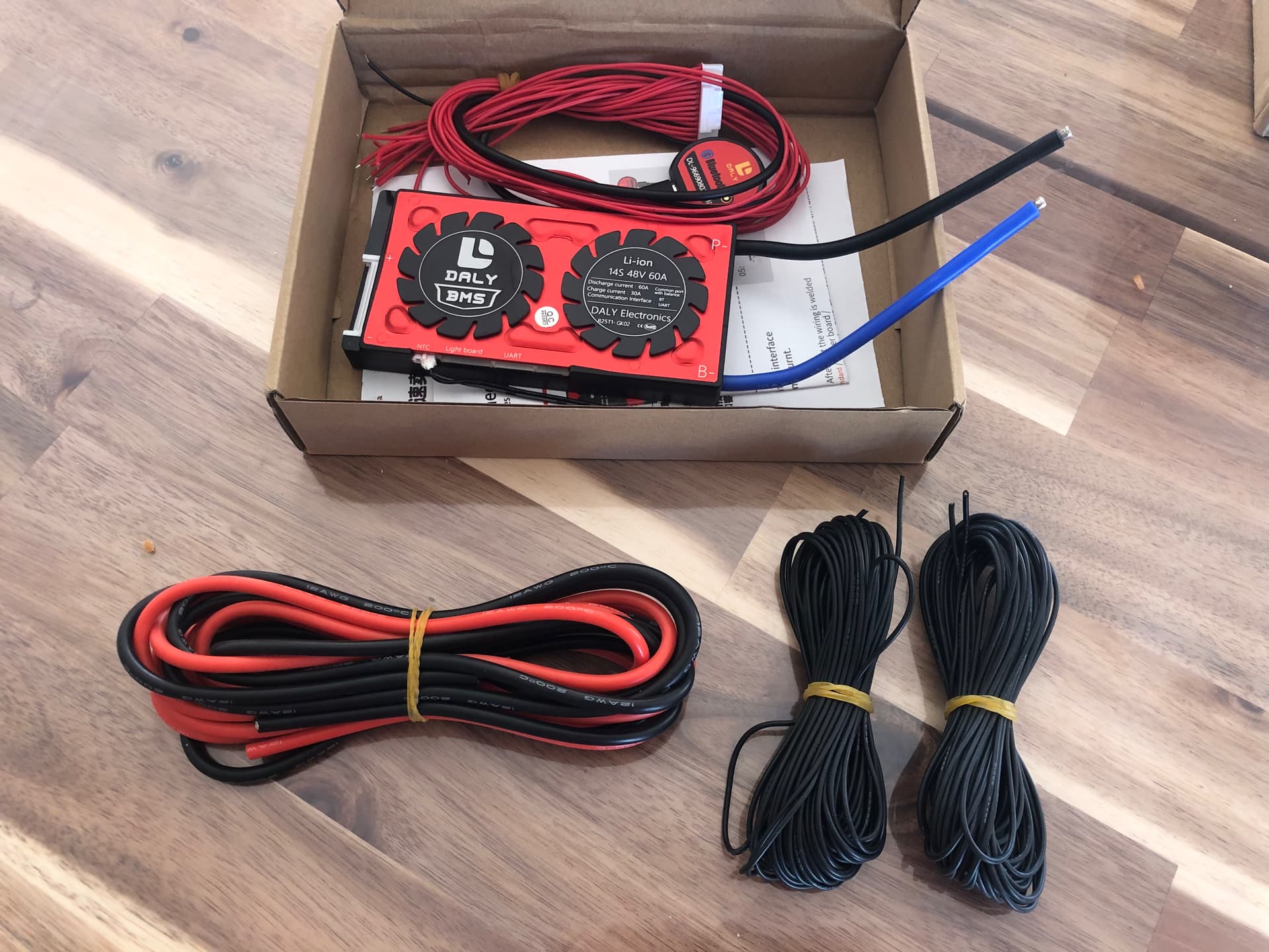
the 14S BMS that will allow me to charge the 14S9P pack (it will be located outside the box) and will connect to the female RS232 cable to balance the cells.
https://fr.aliexpress.com/item/1005002205134036.html?spm=a2g0s.12269583.0.0.42c36ac07K8ri4
Previous order list
- 130 P42 for a 14S9P (with some spares) + 0.20mm nickel
- MakerX HI200 + BLE module v1
- Flipsky 65161 120kv
Remaining electronics
- Remote
As soon as I got the cells, I will design and 3D print the battery enclosure out of PETG. I believe 5mm wall thickness reinforced with carbon fiber on the outside should be enough and keep it strong while ensuring its water resistant ability. Not 100% sure I will put epoxy/carbon to close the battery box like @Wardy did, although it seems to be a very good option. I may use sikaflex 11FC joint and some black duct tape to reinforce.
Update of the day, I’ve ordered
- 4 Surlok Amphenol 8mm connectors (female) and 2 female connectors. That’s another 120 euro going away.
- 2 Fliteboard propellers (2x35e = 100 euros including shipping & taxes)
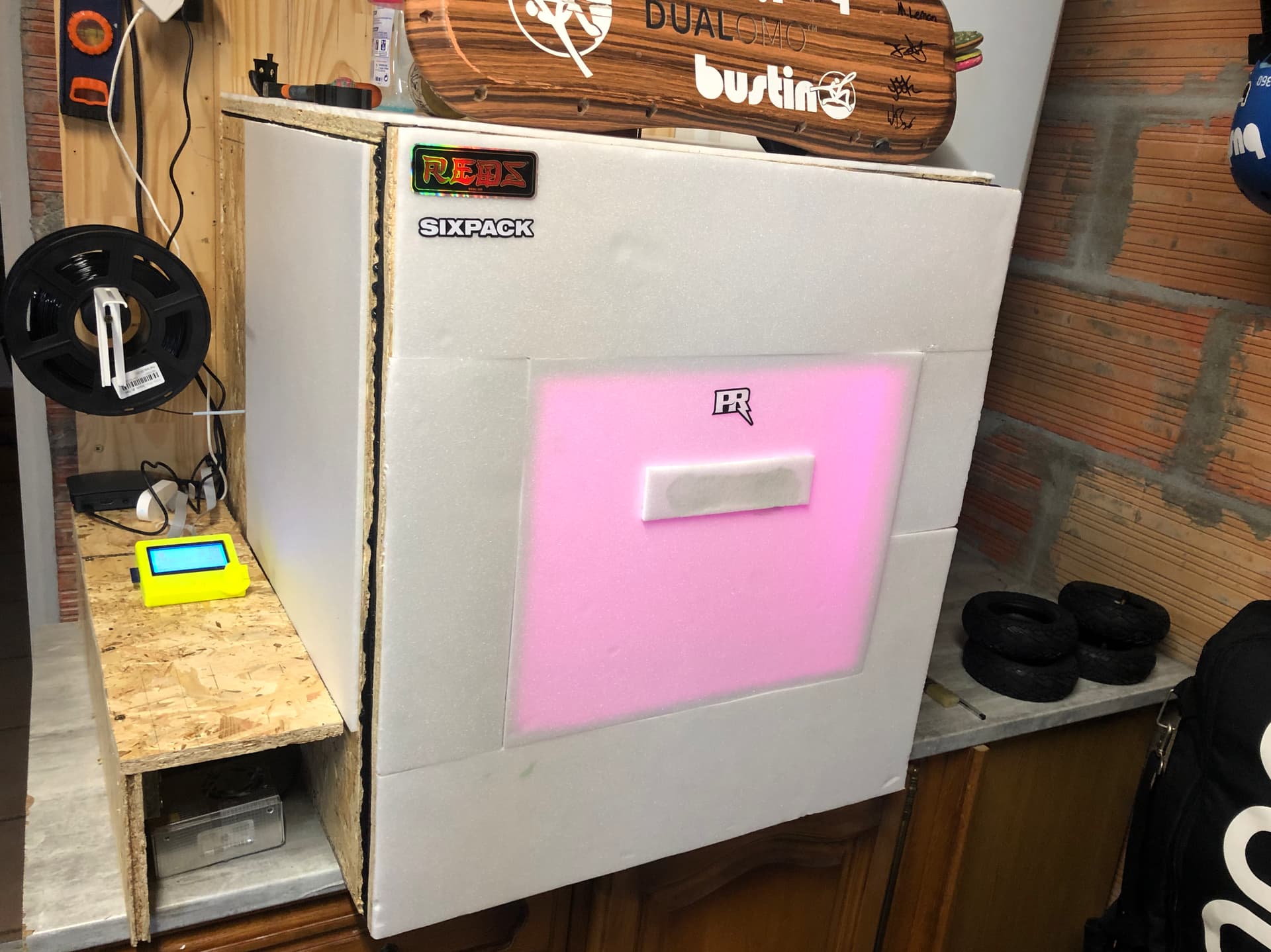
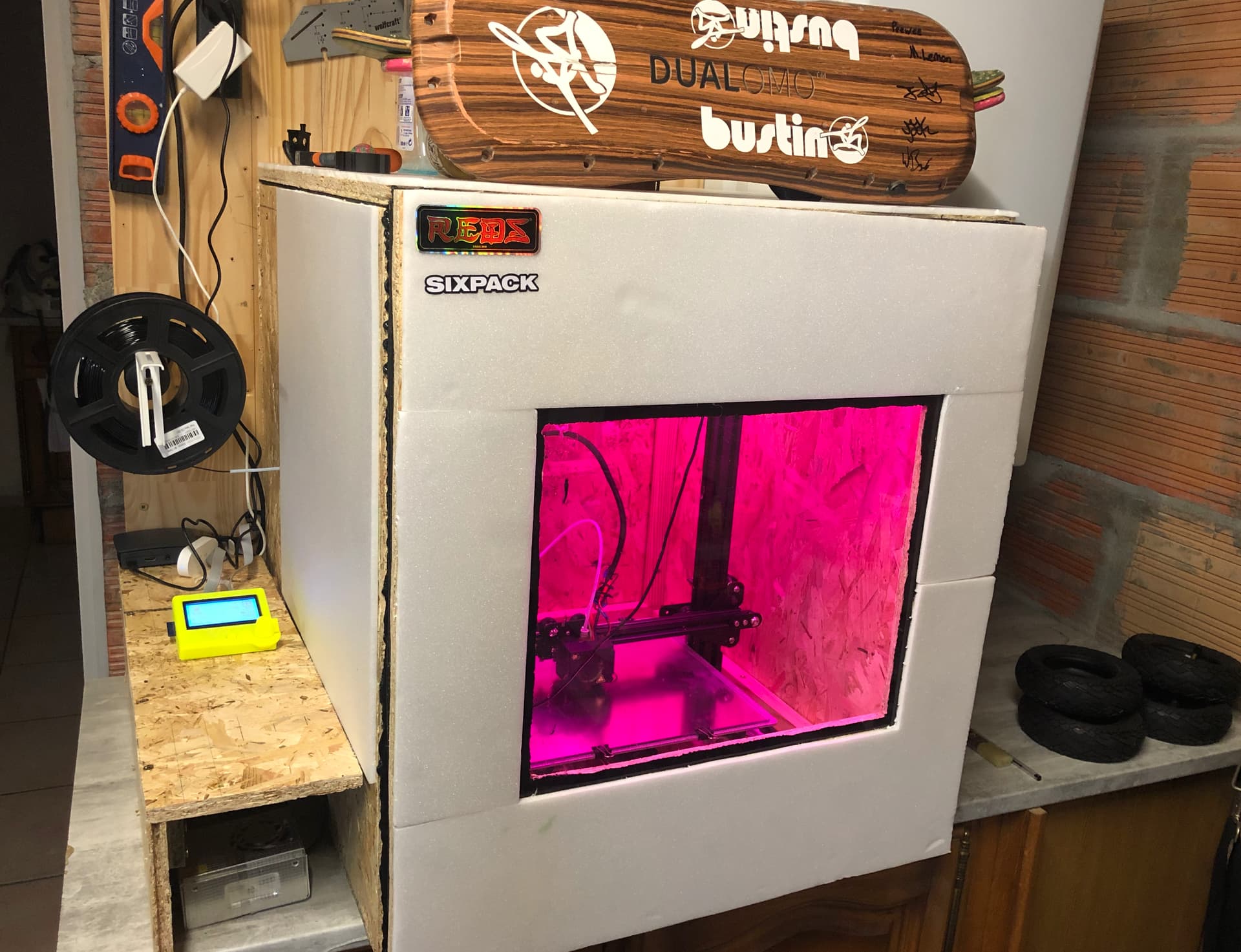
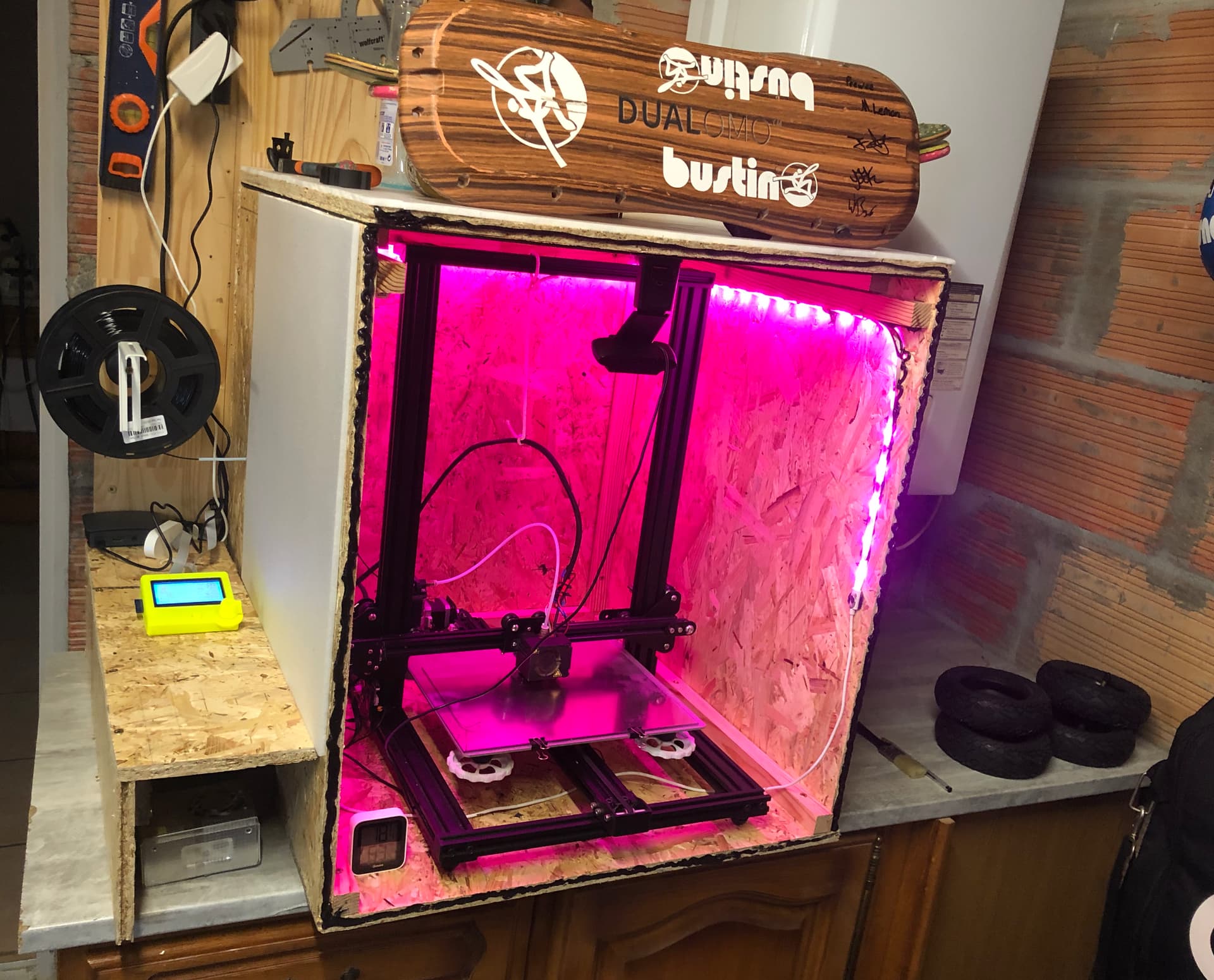
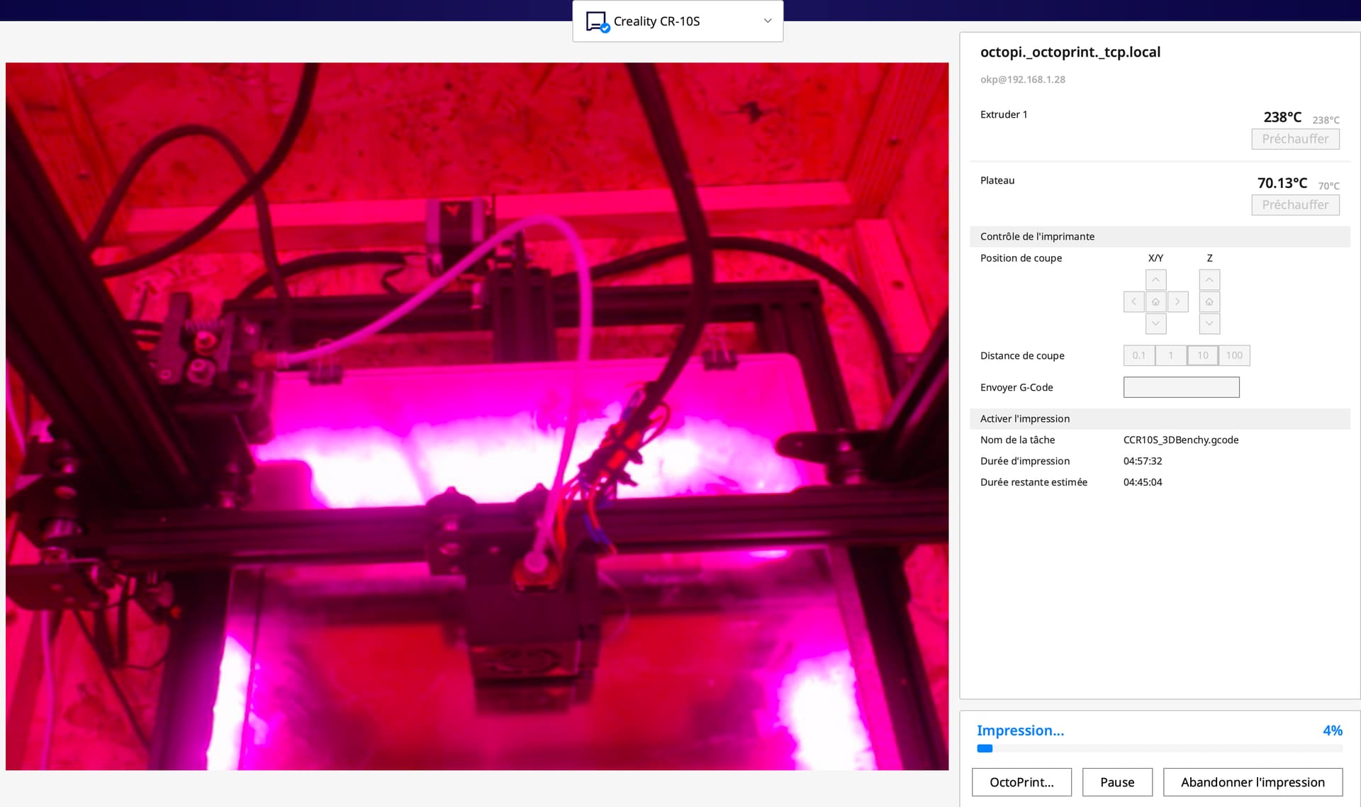
I’m also fine-tuning my 3D printer and made a wooden enclosure for it, especially when 3D printing from my garage (and it’s necessary for the ASA, I’m using PETG for the box)! I’ve also connected octoprint with cura to make the printing exercise a more friendly experience! As soon as I got the cells, I will start the box design and launch the print!
For the bottom & top of the battery box, I was thinking of using 7mm EPS that I will carbonfiber/epoxy to the “walls” made our of 40% infill PETG
Thanks a lot guys for the support and advices
2 Likes
Hope you don’t heat up too much, as I did the same to print in L “ABS” and burnt components and warped some parts of the printer, this type of printer is really not intended to be locked up!
1 Like
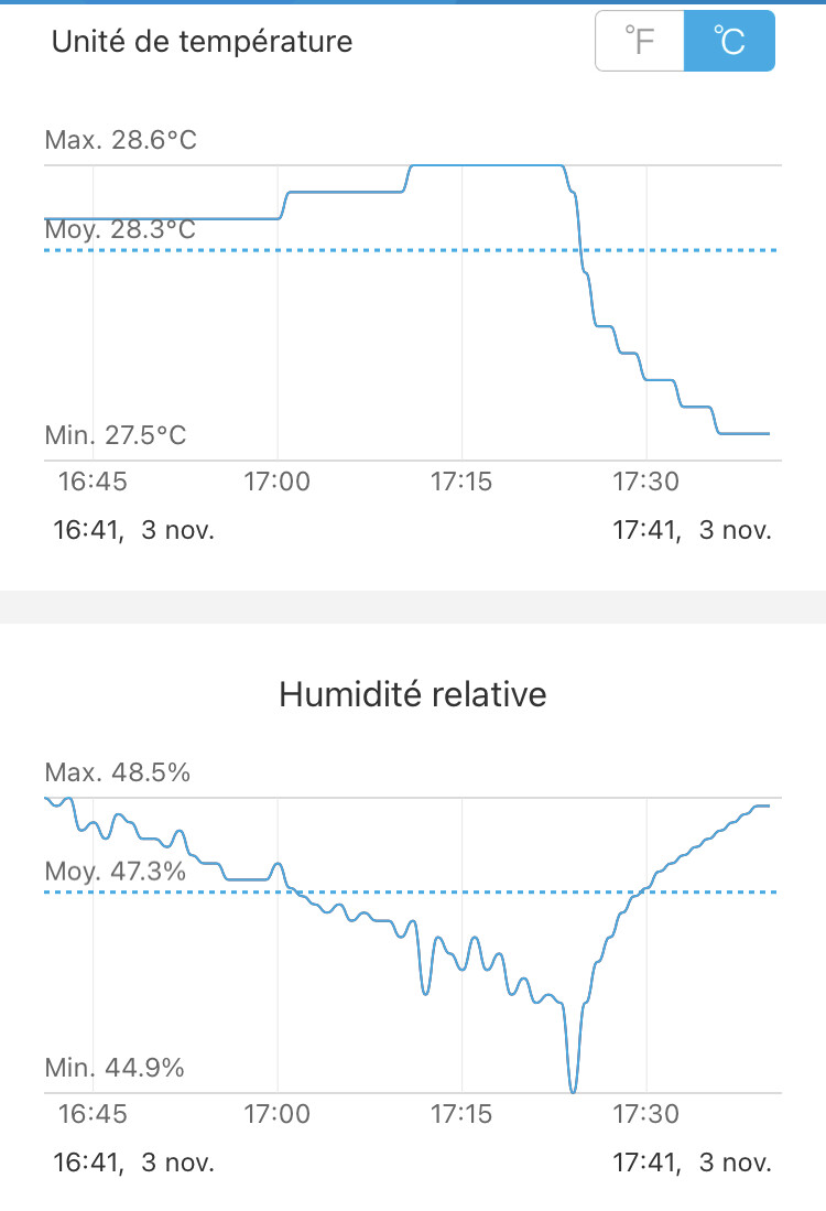
hey @philippe all electronics are outside of the chamber. Maximum heat so far inside the chamber is less than 30°C after 4 hours of print of PETG (Bed:70°C / Hotend : 238°C). I also have a 120mm fan on the top that I will setup with a temp detector at a certain value to extract air if needed.
all good
so, that’s very good 
1 Like
Update of the day - I’ve ordered two propellers frome Fliteboard. That’s another 108 euros shipped to France.

Now waiting for all the goods to come. The Maker X ESC has still not been sent. I’ve email David to know more about it.
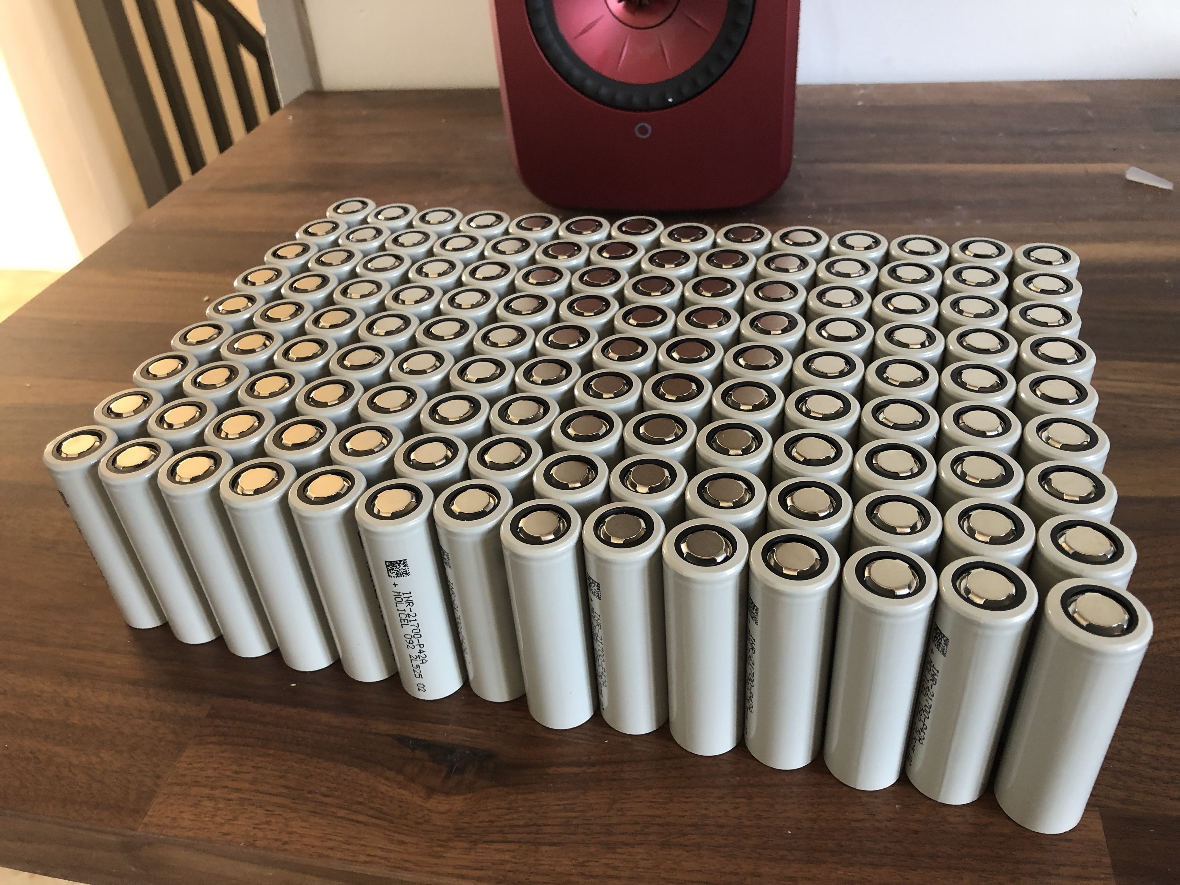
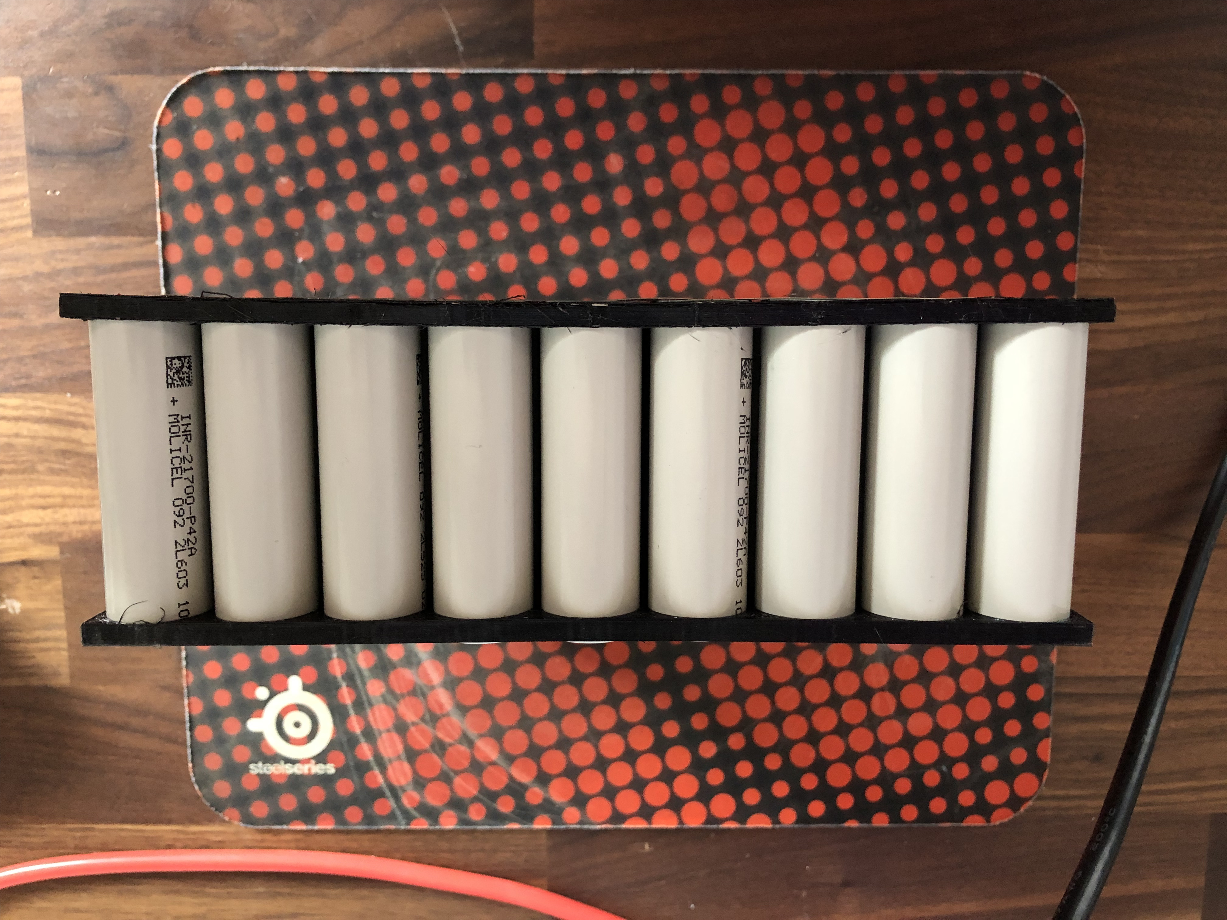
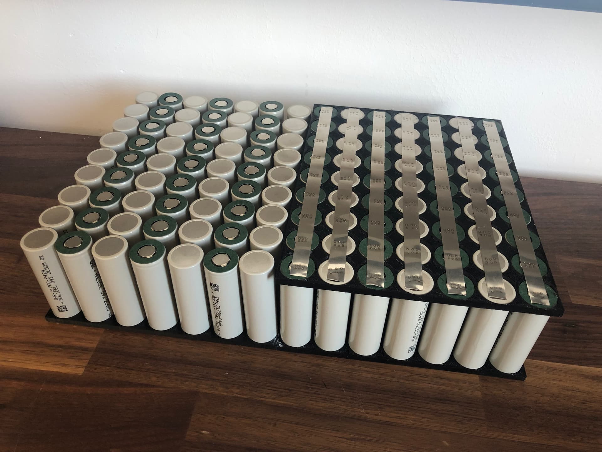
this will do the job ! two more and I start to weld!
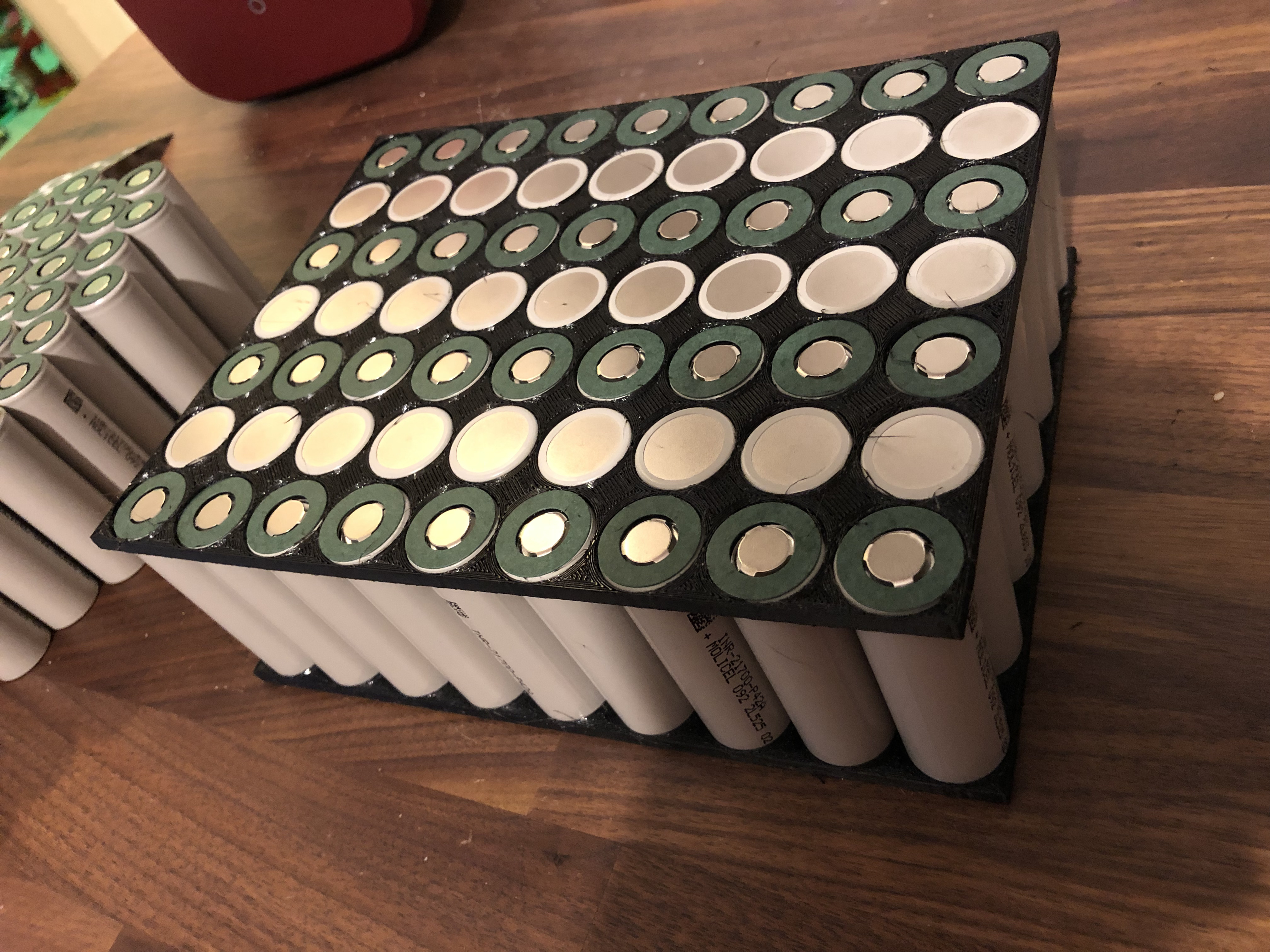
I’ll use 0.20mm nickel and thicken it with desoldering braid, everywhere.
3 Likes
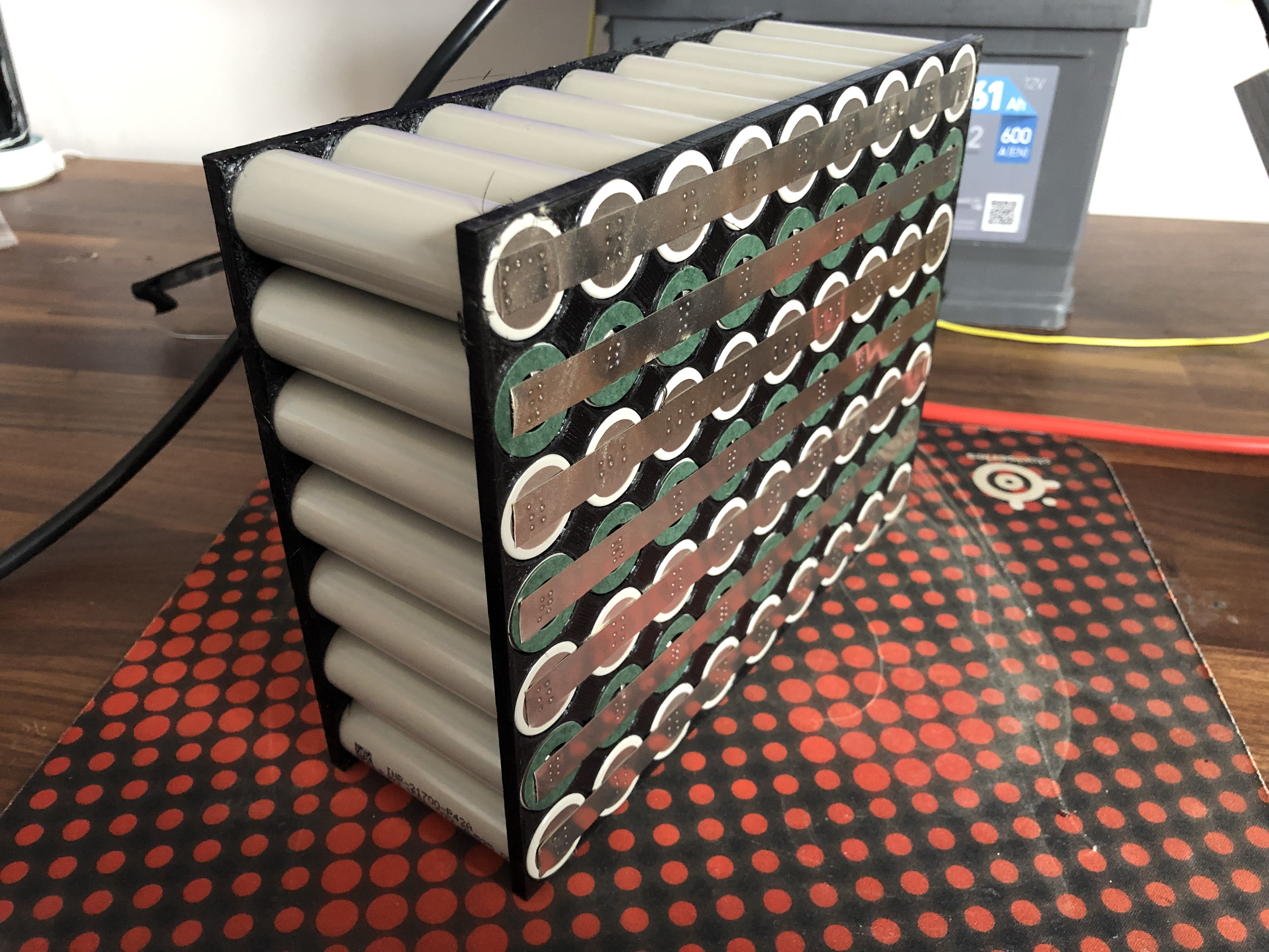
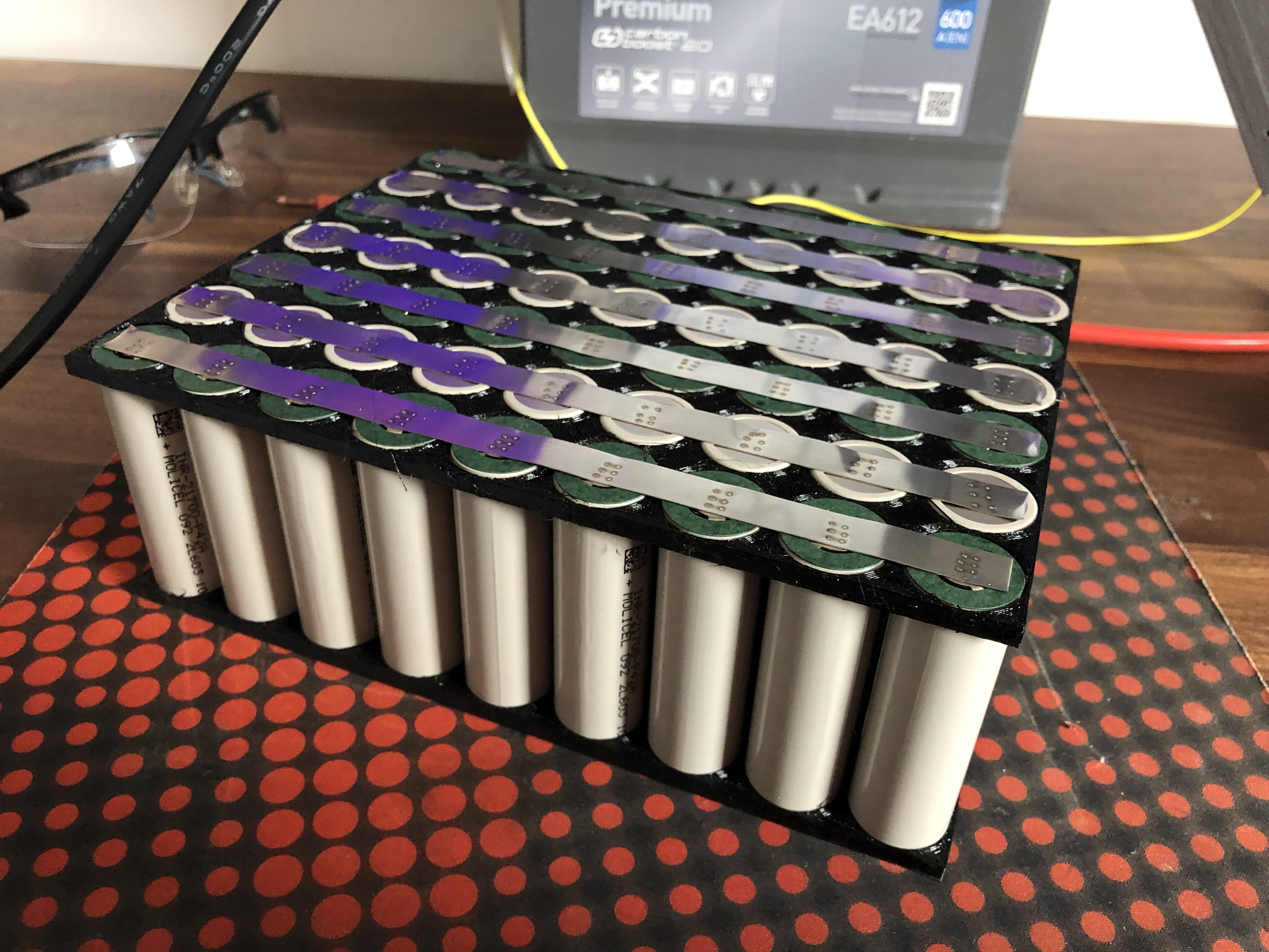
Starting with parallel junctions. 0.20mm / Weld Pulse Duration 0.24mms on my Maletrics Spot Welder. Welds are strong. I forgot how time consuming it was to make batteries.


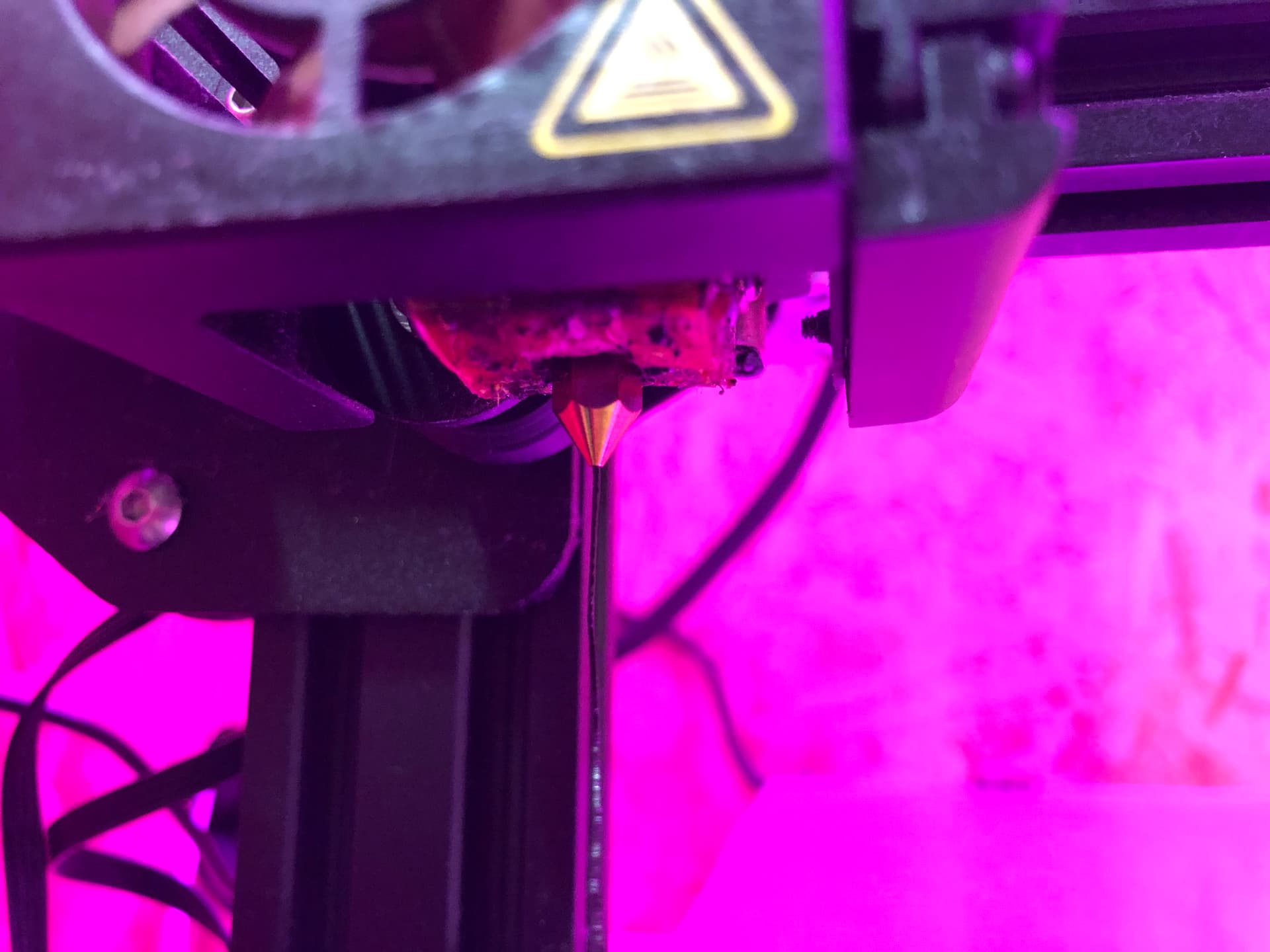
I also took the opportunity to replace my 0.4mm nozzle and replace my old tube with Capricorn one.

6 Likes
hey, slow move is better than no move!
I’m having some challenges with my 3D printer and the PETG filament. Maybe he’s a bit too old but I’ve ordered a new PETG filament and see how it goes. It just delays a little bit my battery building but time is on my side.

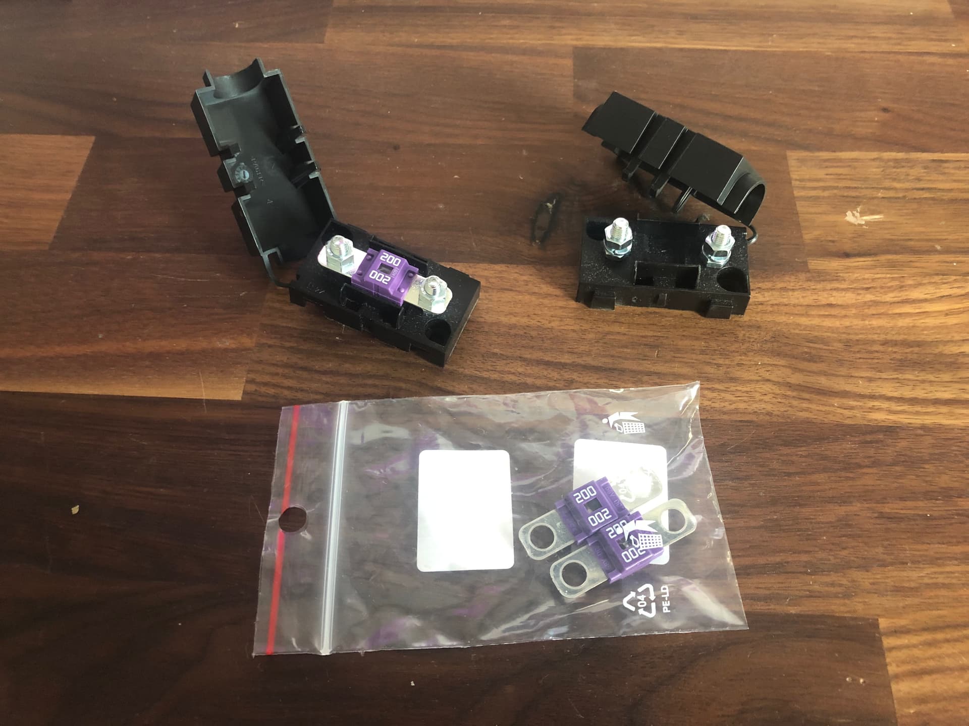
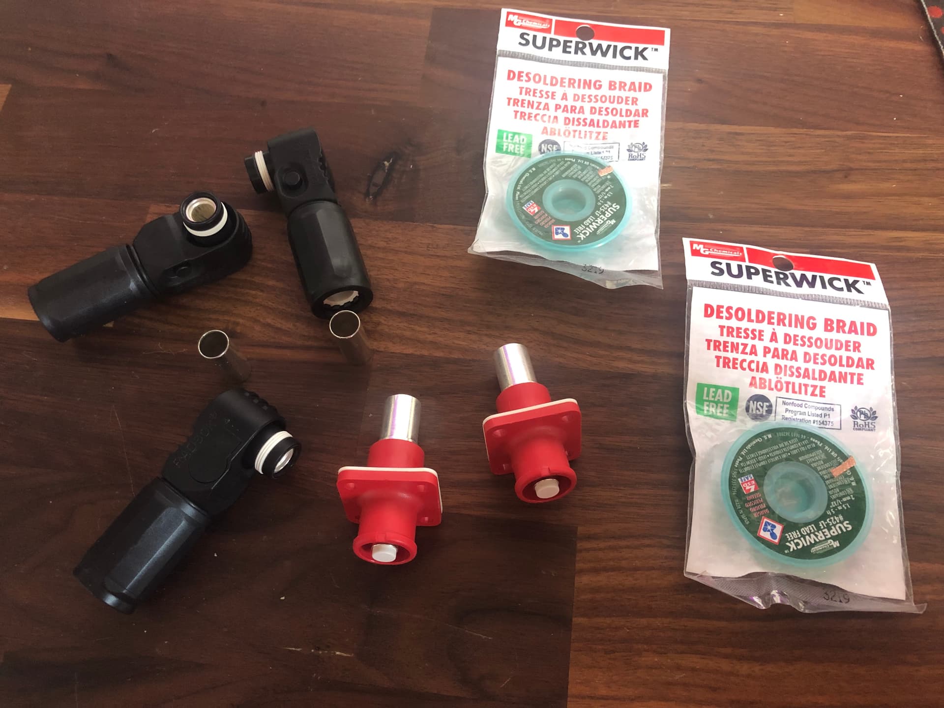
In the meanwhile, I’ve received some parts.
- 200A Fuse & Fuse holder
- Desoldering braid (to reinforce my batterie series connection)
- Amphenol connectors
4 Likes
I managed to print the bottom layer and get the PETG prints working again and I’ve also received some cables (not the AWG8 yet) and the 14S BMS
the top cell holder is being printed and once done, I’ll move to the overall battery enclosure box design.
2 Likes
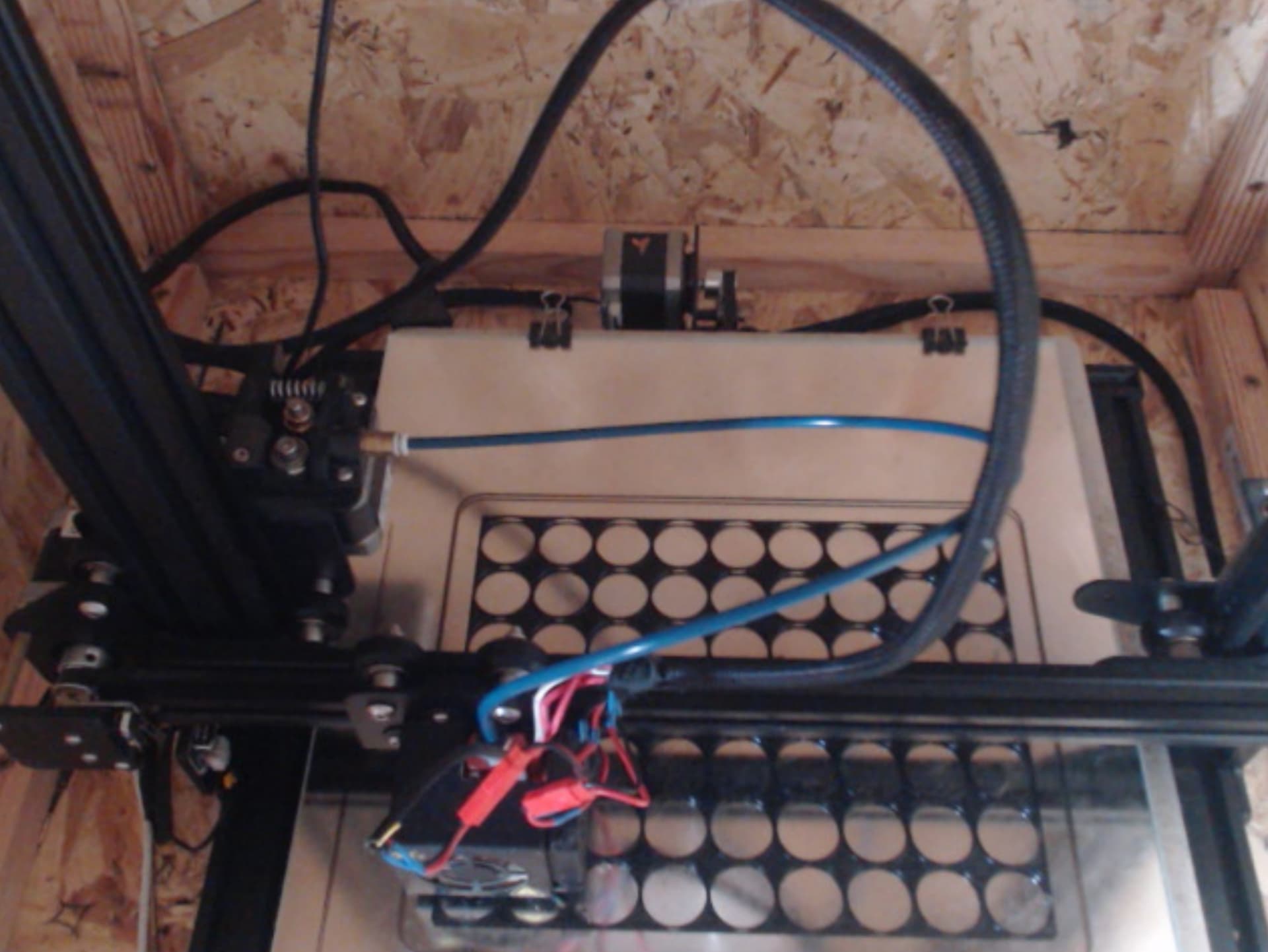
I’m following a similar approach regarding the esc, but instead of leaving it outside, I will leave it inside (see attached pic).
I want to do this since this way I still get the single-cell low voltage cutoff.
I connect the output of the bms to the receiver, in series with a reed switch , attached to a leash+magnet, so that if either a single cell falls below the min voltage or the leash is disconnected, the rx loses power and the motor is turned off after 1 sec. In the future I might replace this with an arduino so that there’s not a 1sec latency between signal loss and motor cut off…
2 Likes