I limited the current with “Current Protection” feature in Blheli. I use the Xcross 160 amp.
I don’t use any fuse, I’ve never had any issue which would have required a fuse until today.
I limited the current with “Current Protection” feature in Blheli. I use the Xcross 160 amp.
I don’t use any fuse, I’ve never had any issue which would have required a fuse until today.
Thanks - What happened today?
Just a bad translation. It is still my daily driver ![]()
I use the connectors that @hangloose made. It uses 6mm bullet connectors in a 3d printed housing and filled with epoxy and 3d print a mold to make a gasket out of 2 part silicone. It might be a bit bulky for what you are trying to do.
https://www.printables.com/model/675063-lmt-6-waterproof-connector-400a
If you can’t print the hangloose connector, See NEW DIY Foil Drive Assist KILLER from Austria - #9 by heiguga
Looks great - what plugs are these?
Just had a quick look at your website - wow you’ve done an amazing job!
The plugs are XT150. They are extremely strong with peak curret up to150A.
At moment I’using them just with dielectric grease in the water.
I’ll design a seal soon
FD released motor stator with MT60 connector inside
Interesting that he says at minute 1 that grease adds resistance to a connector. I haven’t found a proof for that…
So interesting to see their build using MT60’s and fairly low AWG wire. I’m sure they’ve tested the limits in and out of the market. Wonder how close to the limits this pushes things. Very tempted to follow this honestly for a low stress foil assist build. It would certainly make a through-board connection a lot easier. Hmmm…
Yeah I was thinking the same. I did chat about this with a friend who is an engineer and he said it was possible because of it being underwater… it keeps things cool and allows it to handle the current.
I am also trying to figure out a good waterproof solution to passing a cable through.
Was thinking of just passing wire through, with no plug, and moulding resin or sealant around it both sides of the container, maybe with 3D printed surrounds.
Do we know what gauge wire they’re using for the 3 conductor cable up to the ESC? Seems the motor comes with 12AWG but I could swear I saw someone/somewhere mentioning 14AWG?
Yeah FD use AWG 14 (2.5mm2) for phase wires.
My friend who knows this stuff well says the following:
I don’t agree on removing the capacitors, they are on the battery side and needed. It never hurts to use a thicker cable, reduces loss and risk of overheating. It’s a compromise between weight/size and heat/loss. The cable should also match the connector, it doesn’t help to use a large cable on a small connector that overheats and de-solders itself.
Several MT 60 connectors along the route to the ESC, combined with a small cross-section wire, greatly increase your chances of getting a de-soldered phase wire.
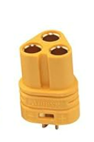
I checked MT60 and they seem to be all arranged in triangle pattern, however FD’s one is flat, are you sure these are MT60?
 vs
vs

The flat one one is the MR60
Yeah i wasnt 100% sure what he meant about capacitors.
And i agree that using 2 x connectors will add additional resistance. My initial version will probably not have any connectors for the phase wire (just solder both ends ) and will use an off-the-shelf waterproof gland to pass the cable through the (under board) box.
I have further optimized my MTW-60.
This time it is only plugged in without a screw connection.
The female side can be installed in the board or on a box. I have created a ring for the built-in socket to glue to the board, for example.
The socket is then screwed on.
!