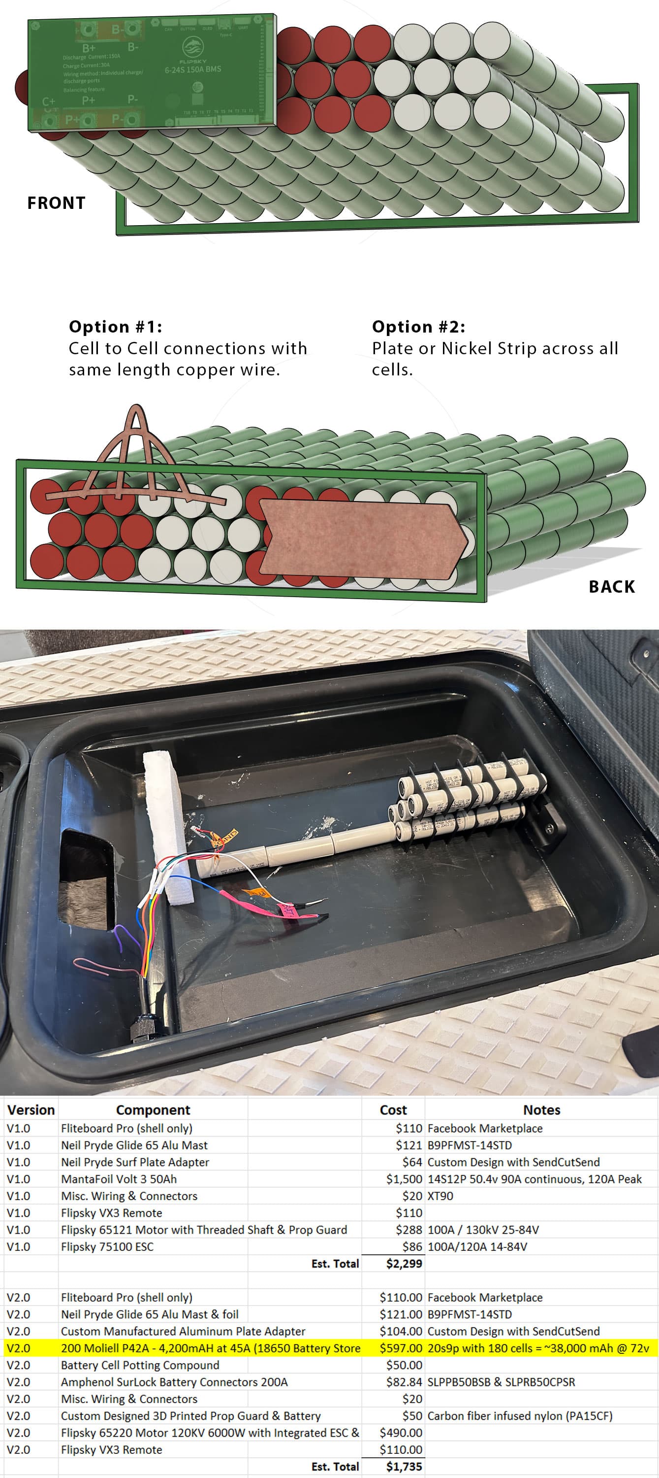
I’ve built an efoil with 18650’s that was slightly underpowered for my weight and board (or I couldn’t figure out how to tune the ESC), and I’m making a v2.0 update with 180 21700 cells in a 20s9p configuration. This configuration requires a connection between 2 sets of 9 cells, with each set adjacent to eachother. I would normally just connect the two sets with a metal plate or nickel strip (as shown in image Option #2), but I am wondering if this may cause too much strain on the interior cells since electricity will tend to take the shortest path through the closest cells in the set. Would it be better to add a plate connecting each set, and then add wires (with the same length) to different parts of the corresponding set so that the electricity has the same length of travel between different areas in the set (as shown in image Option #1)?
Sorry if this is a dumb question, but I’ve never had to wire a battery with this type of configuration.
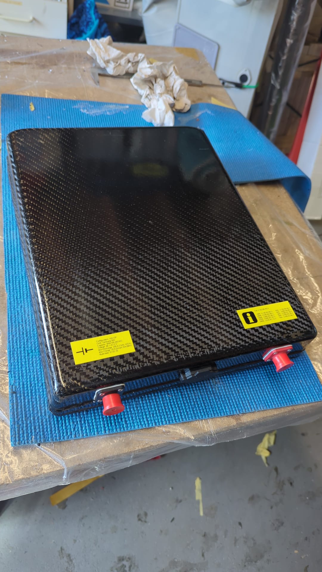
If I’m correct that’s a series 1 board right, can you measure the height within the mainbox?
Why do you position the cells as such? If I’m not mistaken you have 80mm. And the cells are 70mm
Just wondering, why do you want 20S?
Currently also building a pack for my fliteboard.
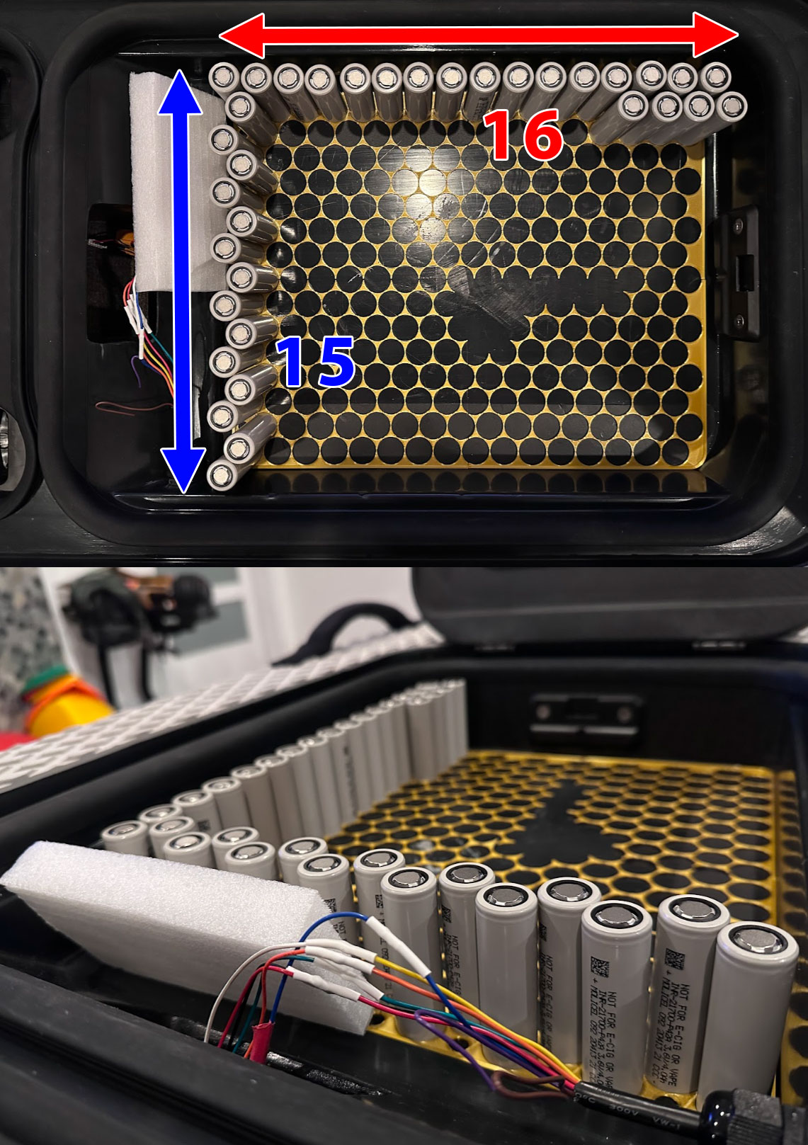
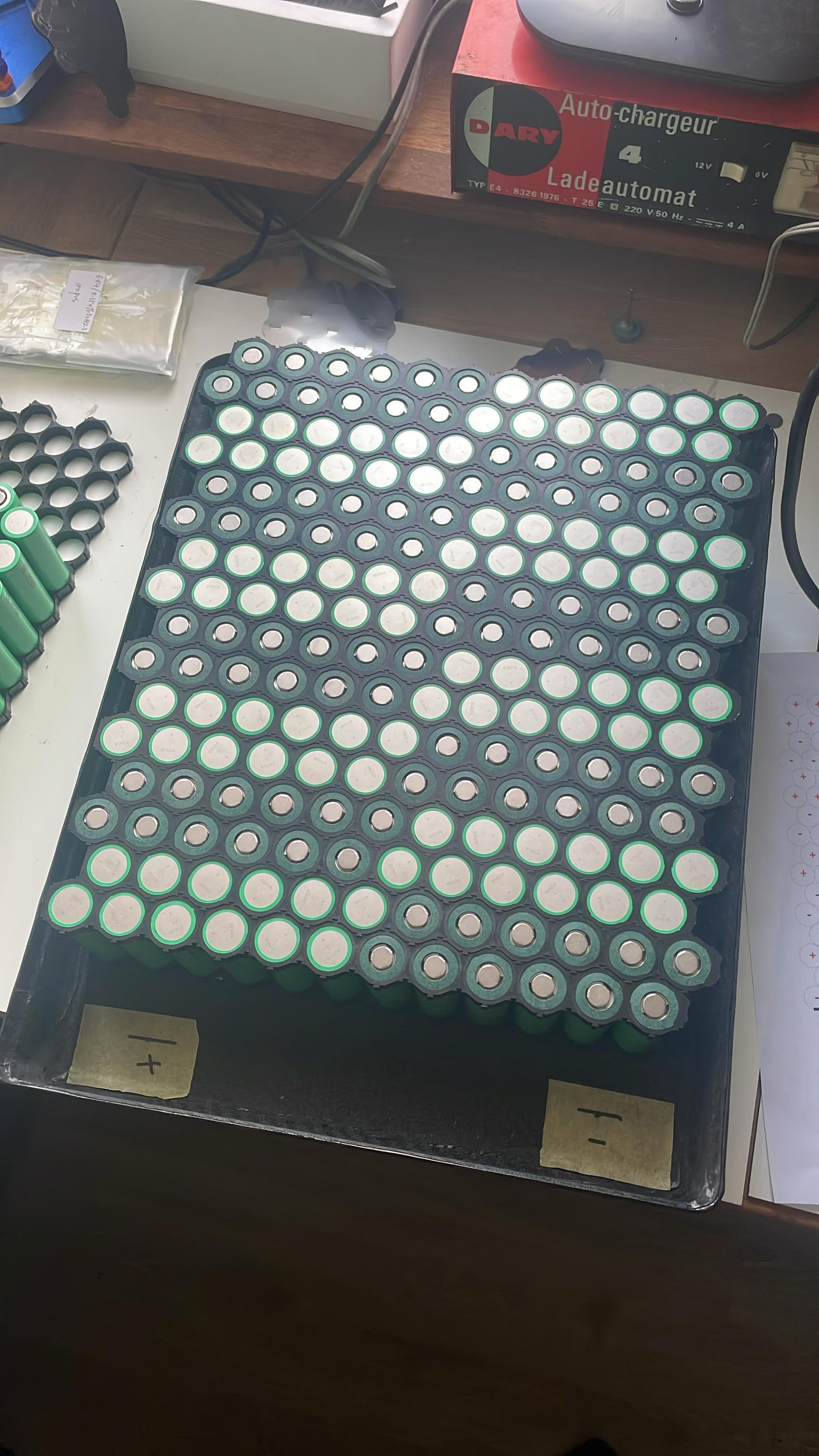
This is a 16S12P. 192 cells in total.
I run my Fliteboard with diy parts on a 10S pack, even that 36V has enough power. Most commercial Efoils use 14S. I think 20S is unnecessary and as @Kian mentions there is more of a shock risk. Just imagine you are all wet after a ride opening the hatch, maybe a bit of water leaked in, and then unplugging this high voltage battery. I think the higher voltage is just more risk than necessary
Regarding your question about the series connections, here is an example that is a bit similar: DIY 14S7P battery build in a Pelican case
I would build a pack in more of a grid and rows style, like @DutchFoiler posted. It should fit in the Fliteboard, but don’t go over 80mm in height! But you could also do an approach that mixes Options 1 and 2 where you run maybe two wires from the middle of one nickel plate to the middle of the next.
Thank you Dutch and others for your helpful feedback. Due to the overwhelming response, I’ll re-think my plan and go with a lower voltage. My original plan was to go with the same design you have, but I was concerned about the clearance and how much room I would have for nickel strips, potting, padding, and the outer layer above and below the cells.
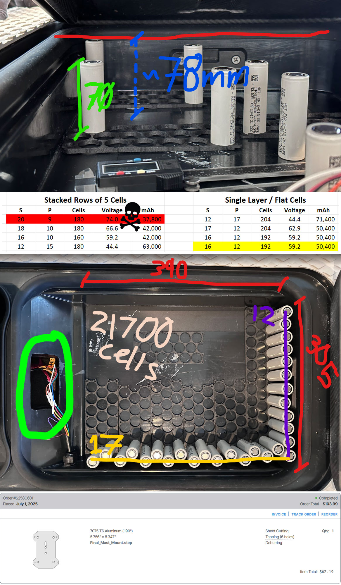
The main battery box area of the v1 fliteboard is approximately 390mm x 305mm x 80mm, but I am getting contact at 78mm in parts of my box. This only leaves 4mm above and below the cells, which is why I originally planned for the sideways cell layout. Your design looks great, so I’ll plan on switching to that and adding some carbon fiber wrap and/or carbon plates on the outer shell with ~2mm of potting compound at the top and bottom. Five questions for you:
Are you planning on a) potting the entire battery, or b) just the terminals (to leave space between the cells for airflow)?
Why did you choose to orient each series with two rows rather than one? I assume so, you have the positive and negative terminals on the same end, but wouldn’t a thick-gauge wire running 300mm to the other side of the pack work as well?
Is the flipsky LTC6811 BMS (6S-24S 150A - $225 USD) overkill for this battery (powering a Flipsky 65220 motor/esc (120KV 6000W)? The next size down only goes up to 14S, so I was curious what BMS you are using.
Does your fliteboard have a waterproof door or plug for the hole between the Mast Mounting/ESC area and the battery box (green circle in image)? Mind didn’t come with anything, and I wasn’t sure if this was intended to be a waterproof barrier.
Can you share the base files for your battery design?
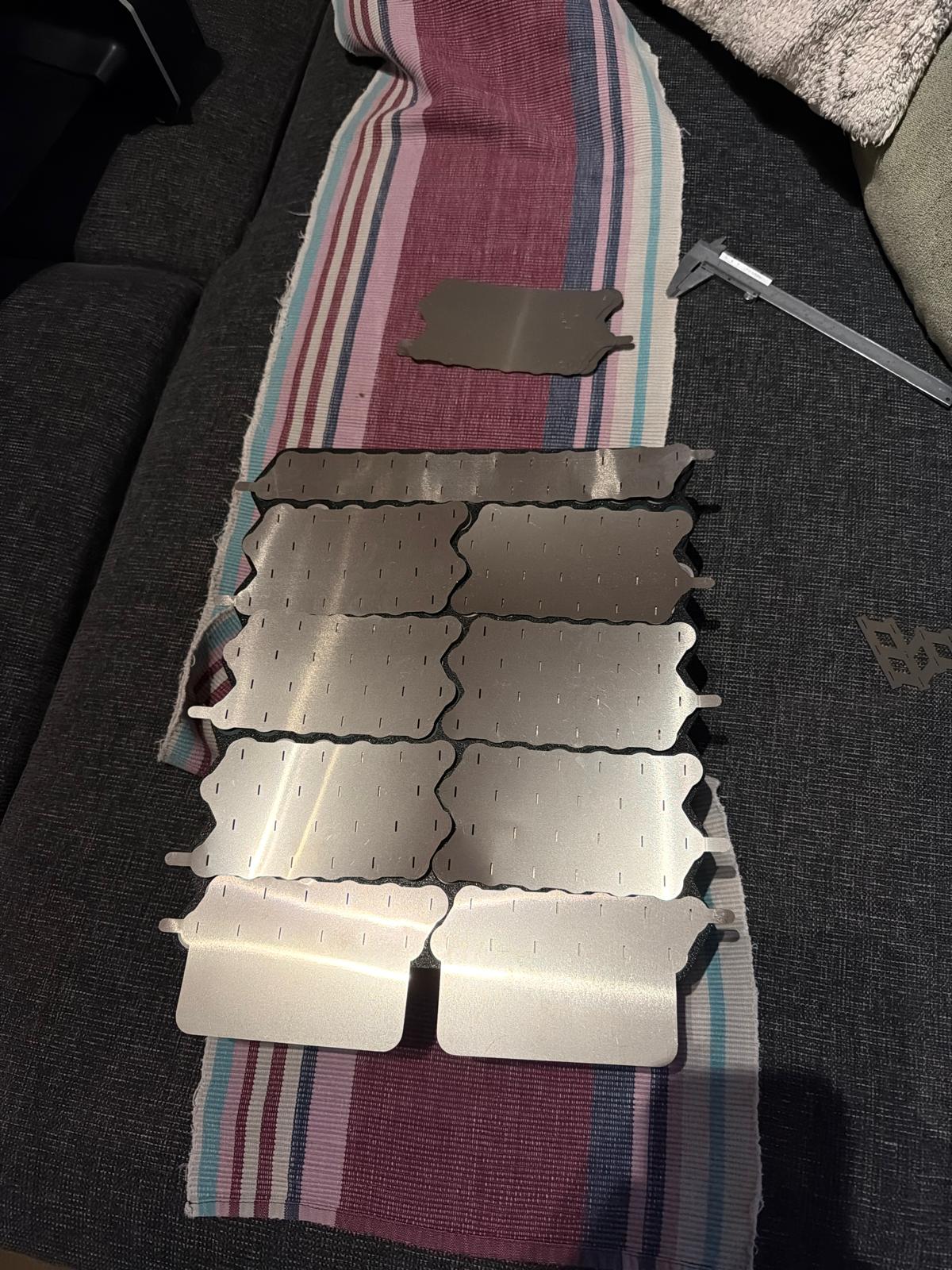
I created a custom mounting plate replacement (see bottom of image) for the fliteboard v1 which allows for easier mounting of aftermarket masts and has large enough wiring holes to fit 8mm bullet connectors. I’m happy to share the files if you want them. Also, we have several iterations of 3D printed motor mounts (link) for the board designed to take some common chinese motors.
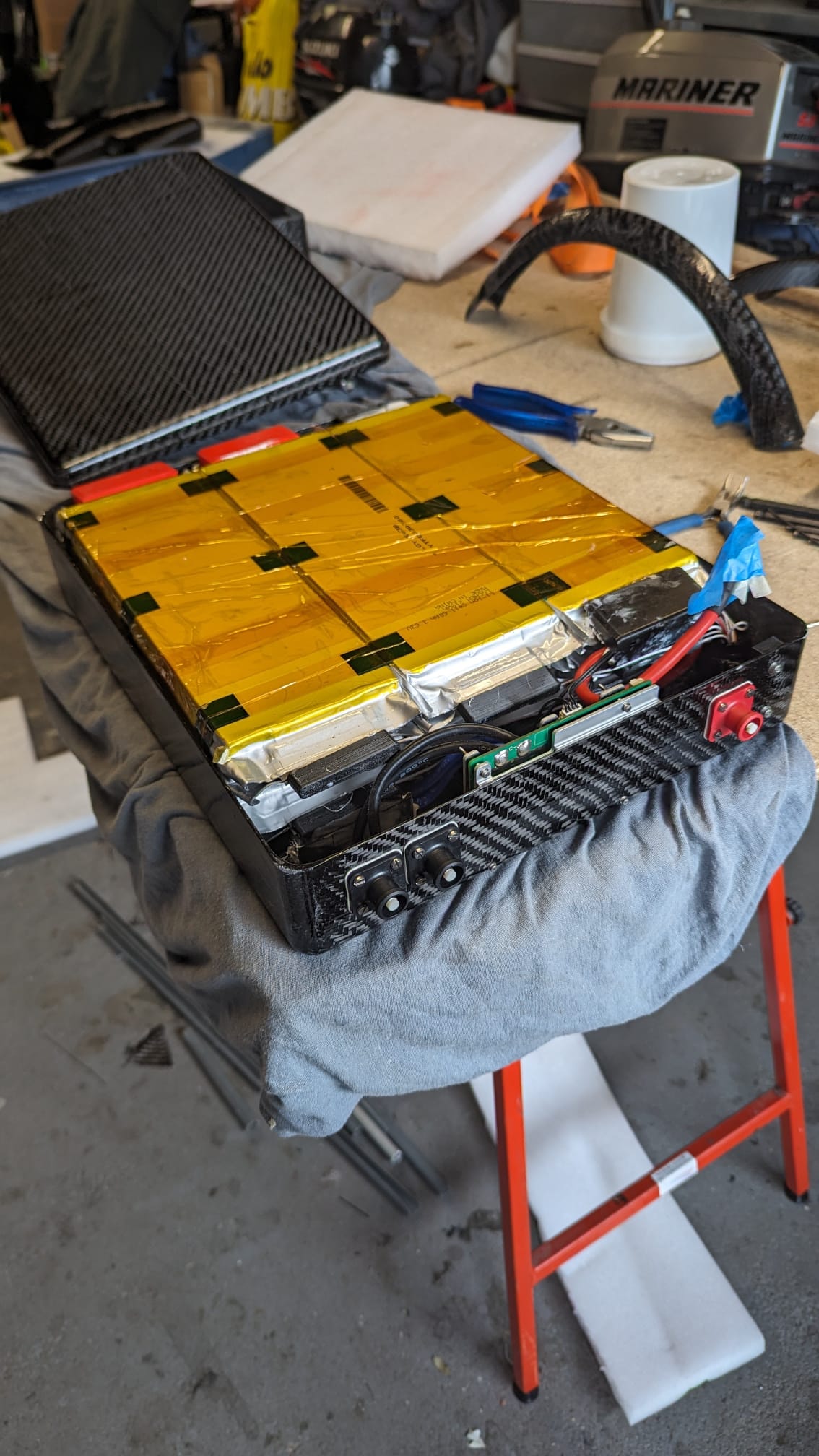
Thanks Roger! I agree that the voltage risk is scary. We purchased a brand new MantaFoil v3 battery last year thinking it would fit into the battery box. It was a bit too tall, and I ended up deconstructing the entire battery down to the cells and rebuilding it. My plan is to copy the techniques used in that battery construction, including waterproof potting, multiple shells, and 150A Ampherol connectors. Based on the feedback, Ill stick to 14 or 16S.
Maybe 80mm will fit, you can play a bit with adjusting the levers for closing the hatch from the inside.
For your questions:
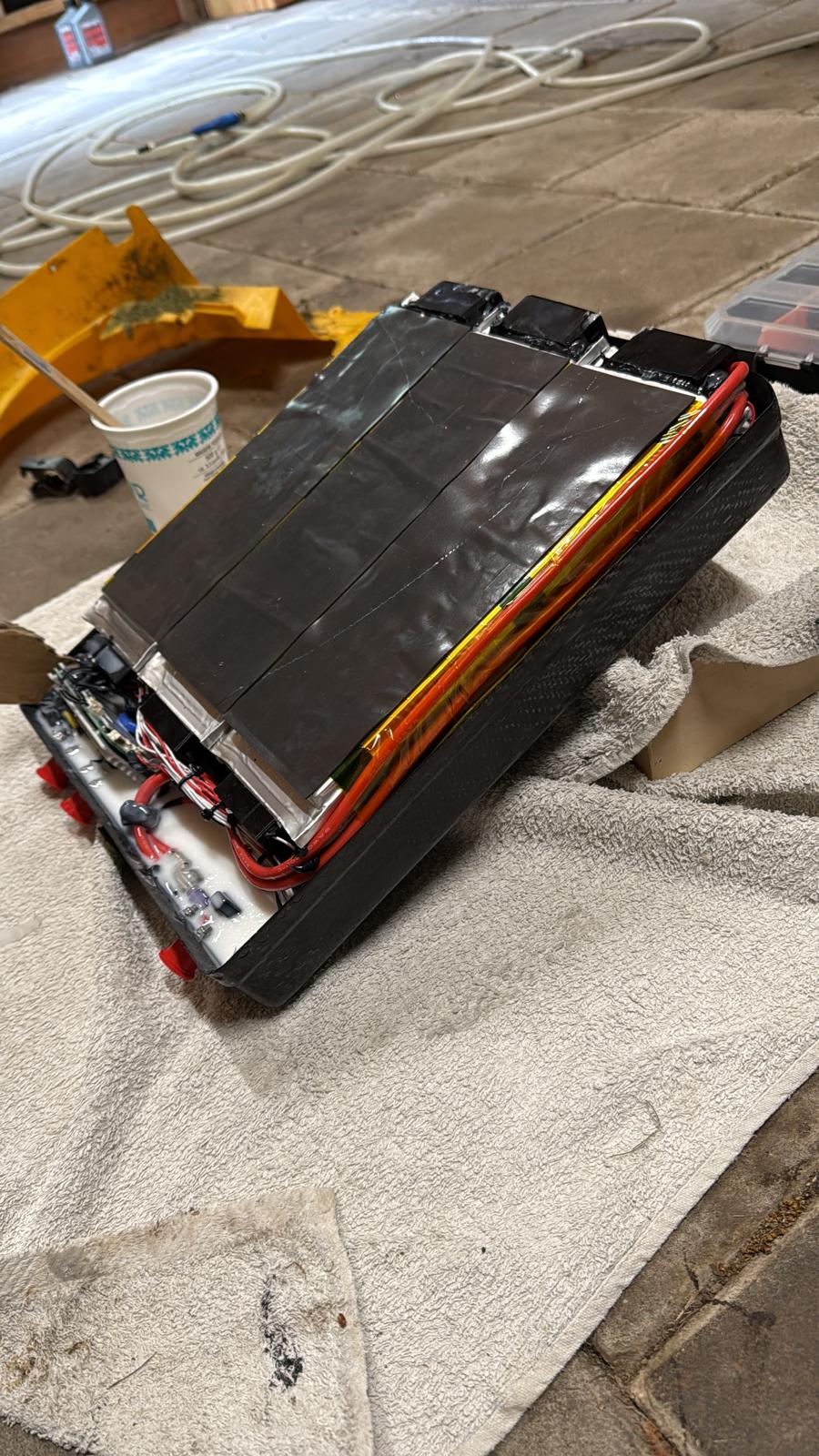
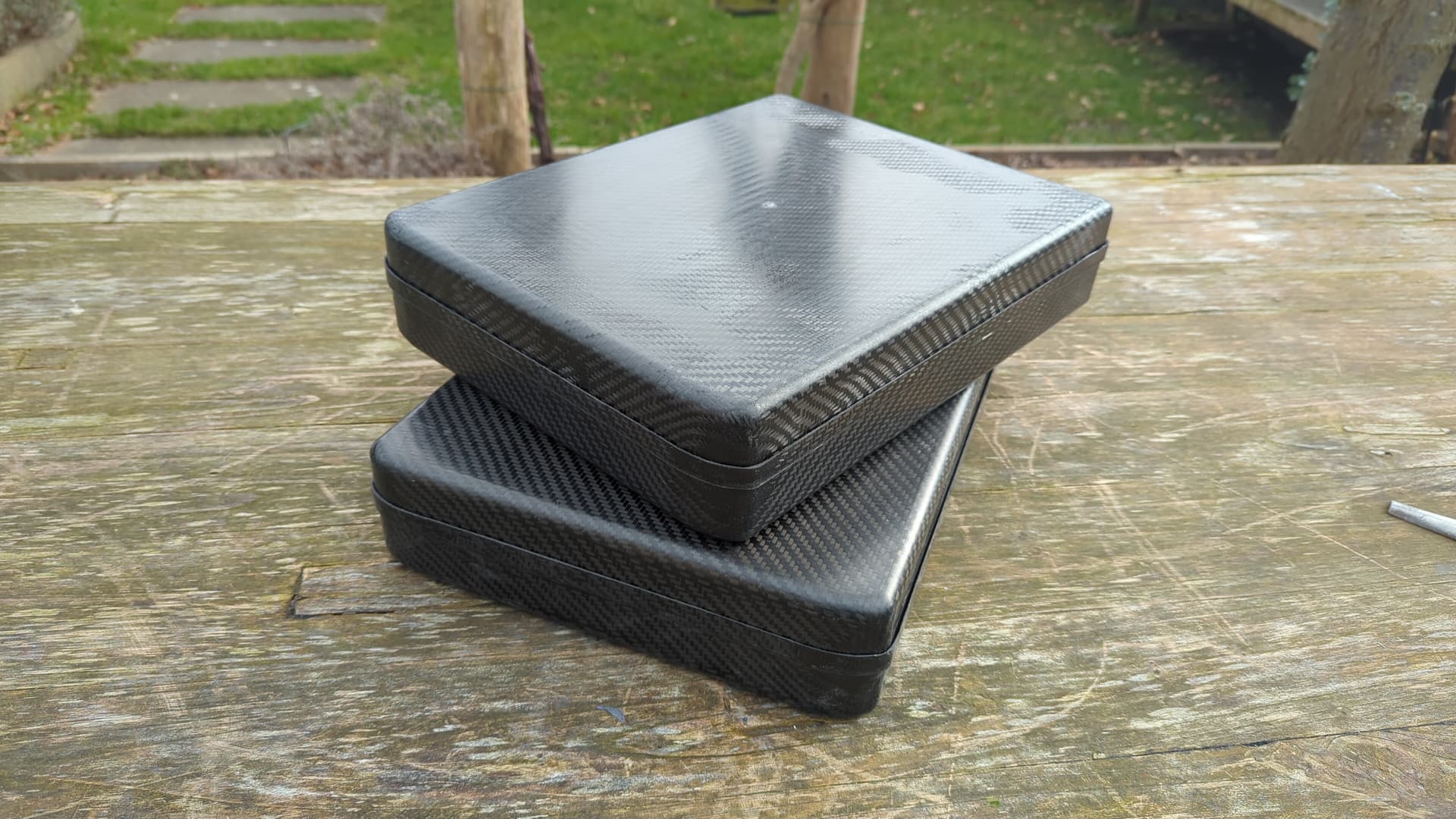
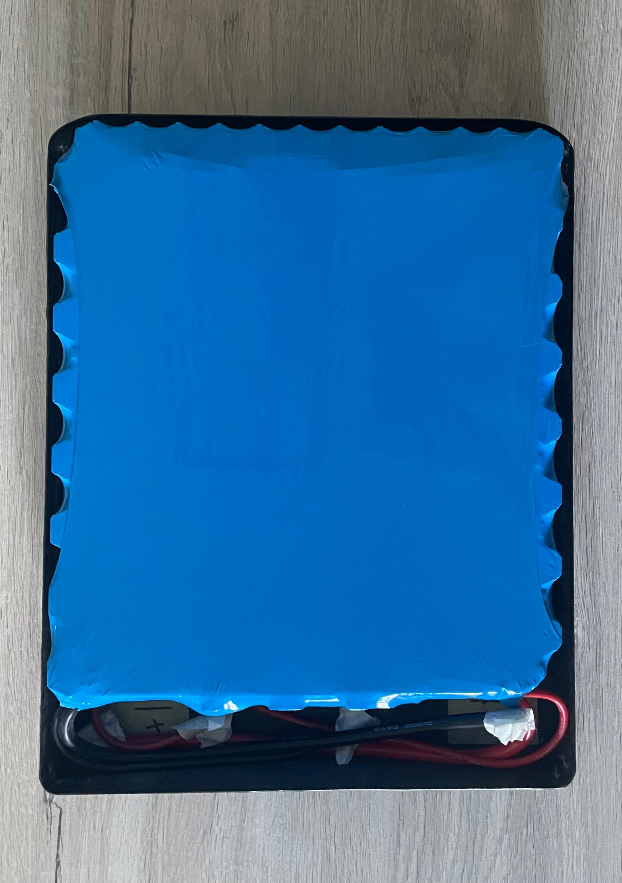
1: No I wont pot the whole battery. Ill be making sure its waterpoof by indeed waterproofing the connections from the inside with tin-cure silicon, which works great. Btw, this is my previous battery, which I sold to a friend, the 16S12P that Im building now will be its successor.
2: You are correct, but there wasnt any space to run the wire. This is the absolute maximum that can go within the battery case. Im aware that having 16 lines of just 12 cells is more ideal, but Ive got some custom cut busbars which are 0.2mm thick pure nickel, so it can run plenty of enough current.
3: The BMS is fine I guess, I have no expereince with the BMS’s from flipsky, it might be a bit pricey as it is a VESC BMS which you don’t really need, theres no real benefit. Personally im using this one
Besides, since you already have the available place to have a mastbox, checkout the Frankenstein build from Kian, so you can use a 75200 vesc instead of the motor/esc combo which i dont like. The wires are very thin (all 10awg), it can run only on fairly low currents, ive seen cases in which the esc already arrives dead and you cant really replace it, so it would be much, much better to just use a 75200 which is much much stronger.
4: Its the same as yours, im using an adapterplate from @Kian to mount a gong mast, on which you can mount the 75200. The orange flange seal in the board should form a waterproof barrier when the mast is mounted, Ive never had any water intrusion.
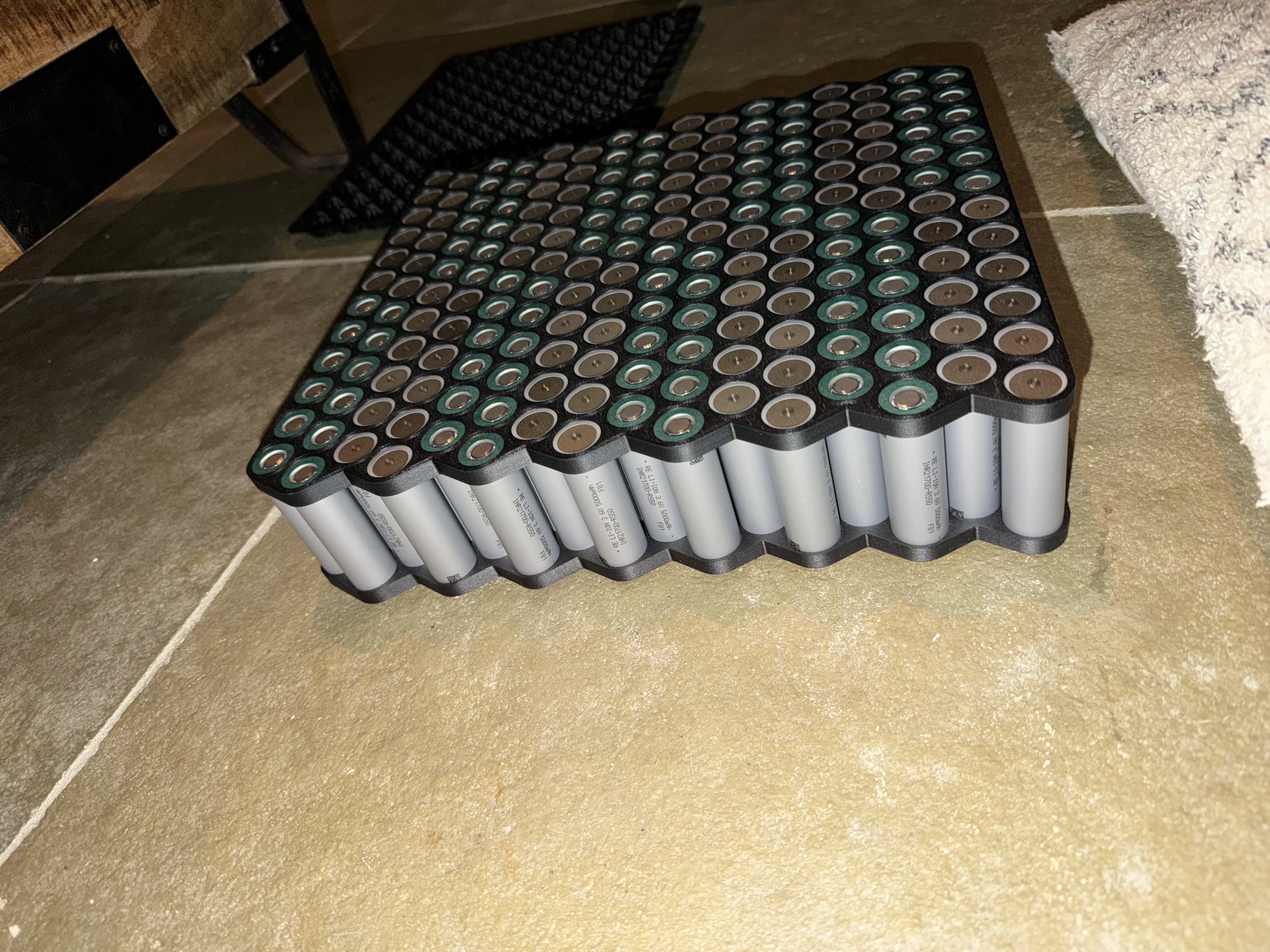
Don’t want to hijack this thread too much, @DutchFoiler i really like that old pack with reclaimed EV cells! How did you end up attaching the tabs for series connections? Solder or mechanical fasteners? That’s one of the challenges with repurposing those flat pouch cells.
Youll find how he made the 15S1P, i did it similar.
Note, you do need to have copper tabs, or at least one side of the tab needs to be copper for soldering. So you can logically structure the packs.
Instead of soldering, you can also just drill 3 tiny holes in the tabs, and screw them together nice and tight.
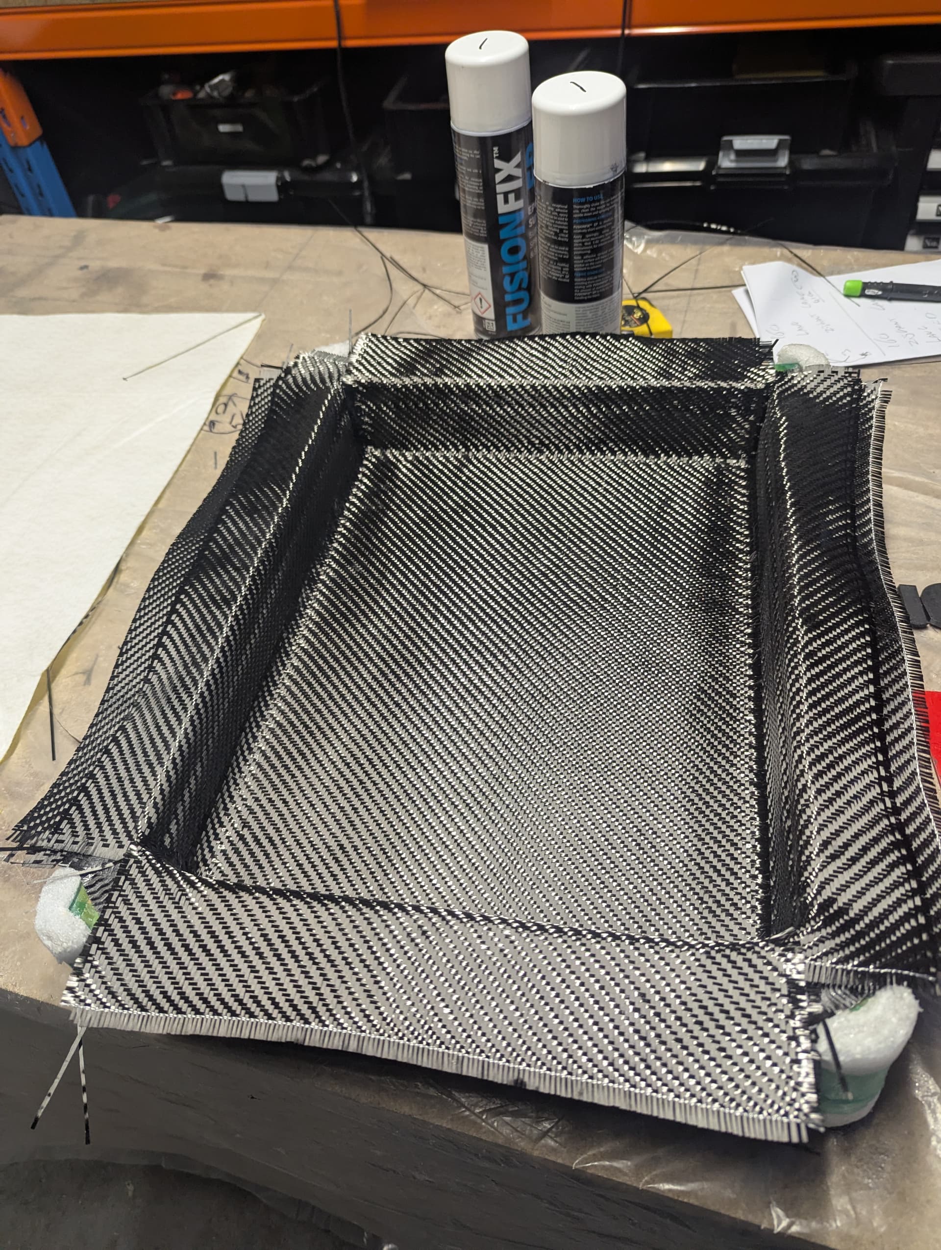
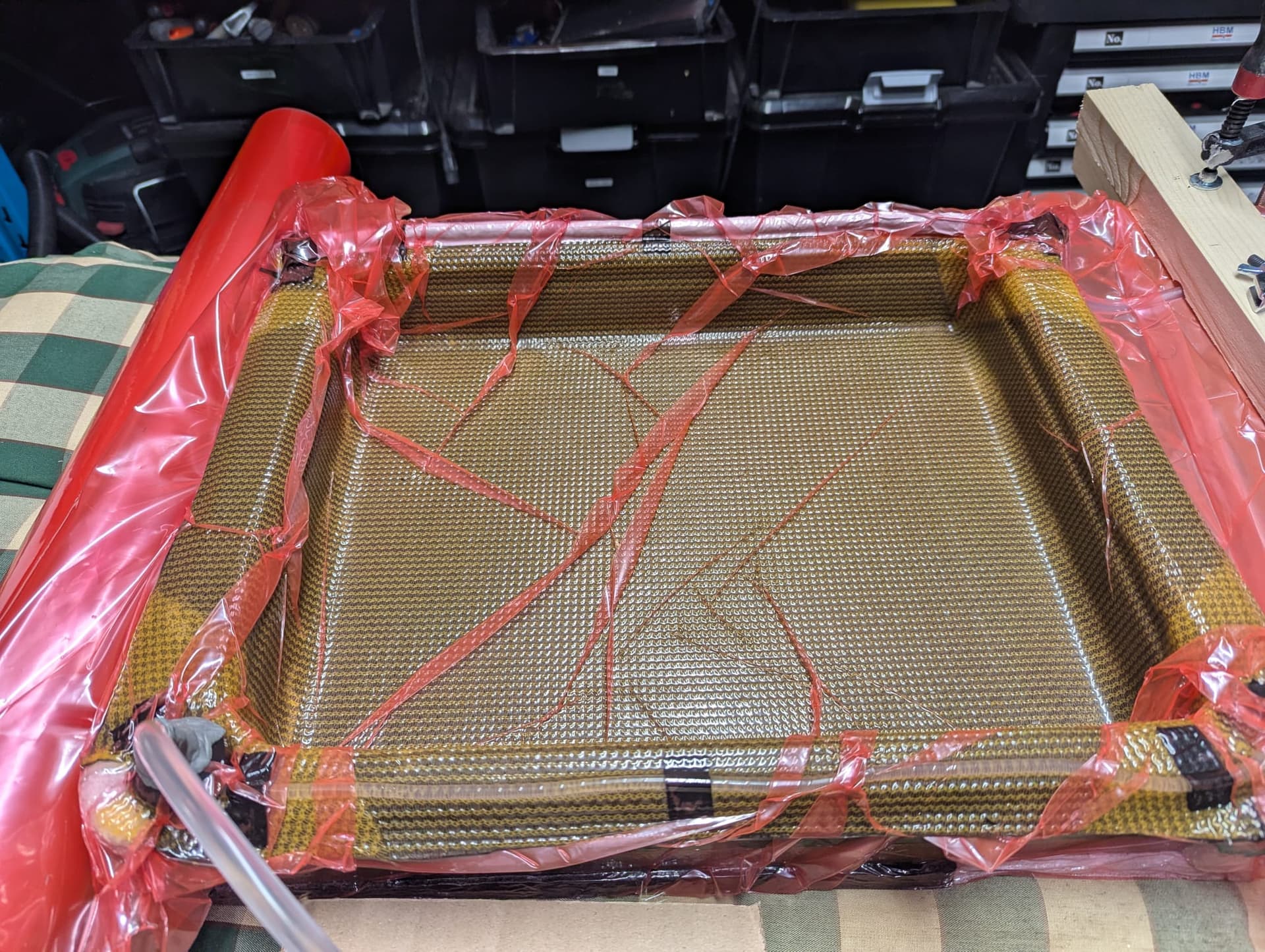
That is a cool design… Did you make a carbon fiber mold of the inside of the Fliteboard battery compartment and use that as the outer battery shell? I was thinking of doing something similar.
I updated my cell design and found that the case appears to fit a 16s15p with adequate room for padding and a small BMS (where the white foam is).
I’m not sure if this application requires a flipsky BMS with expensive features. It sounds like you are just wiring directly from the cells to the ESC (not through the BMS) and only using the BMS for balancing and charging? I’ll go that route.
I was going to see if you could share the cell holder design file, but I ended up designing something similar.
The pouch cell design looks very interesting! I’ve built a few smaller projects using old laptop pouch cells in series, but never thought of automotive pouch cells. I’m curious what type of spacing and heat dissipation they require relative to 18560 or 21700 cells.
I’ve made a pack myself with reclaimed pouch cells. They tend to have extremely high current capability, like 250-350A per cell. So even with a 1p pack they are very capable. My 10S pack never gets hot, barely even warmer than ambient. Efoiling just doesn’t stress the cells much. If you’re in the USA I can point you to a good place to order them
1: a friend of mine makes these with a special mold, they are really nice! Special thanks to @Kian
2: you still need some space for a casing and bms, 16S15P sounds big, very big. I can hardly fit 16S12P, and the case I use is simply a few mm thick. Reccomend to double check or down size a bit. In all hoesty, i dont think this is a wise idea. Reccomend to use the layout I shared, 16S12P, that will fit and gives you an insane amount of energy when using 5Ah cells.
4: If you want I can deliver you all the files which I used for my 16S12P. And again, 16S15P is too big, atleast, thats what I am thinking.
The pouch cells work great, no heat issues, its a 15S1P, has around 3.2KwH, and doesnt get warm. The one I have goes to a friend, and I wanted some extra voltage, plus the benefit, that with the cells I use (reliance RS50’s), theres barely any voltage drop, so I can ride faster for a longer period of time.
You may already have the cells you need for this (very large!) pack. If you want to try the reclaimed EV cells you can browse here:
They offer free shipping, at least in the USA. It ends up being so so cheap. I picked up the Volvo xc90 module. The cells are 32ah, so smaller than some. But they are configured as 16s1p, so you can keep the factory welds and break it into two stacks of 7s or 8s. In my case I did a single 10s stack and it fits in my Fliteboards