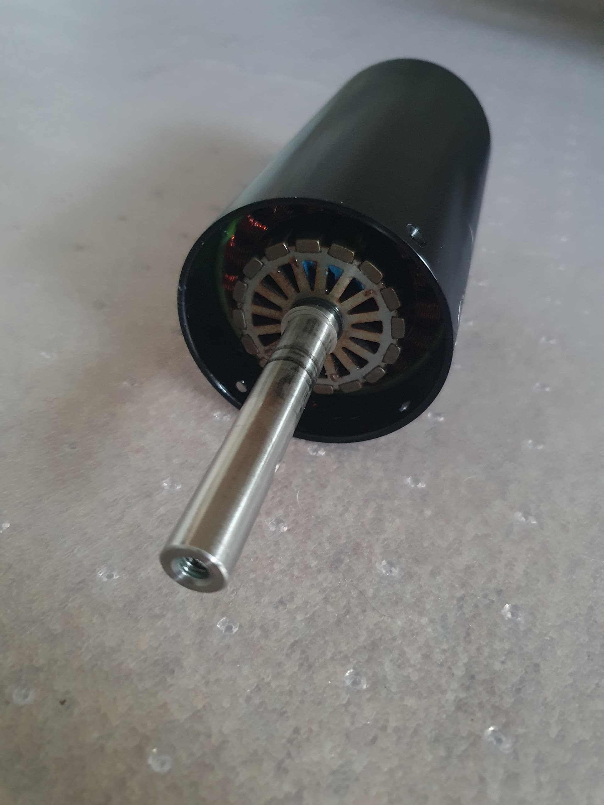
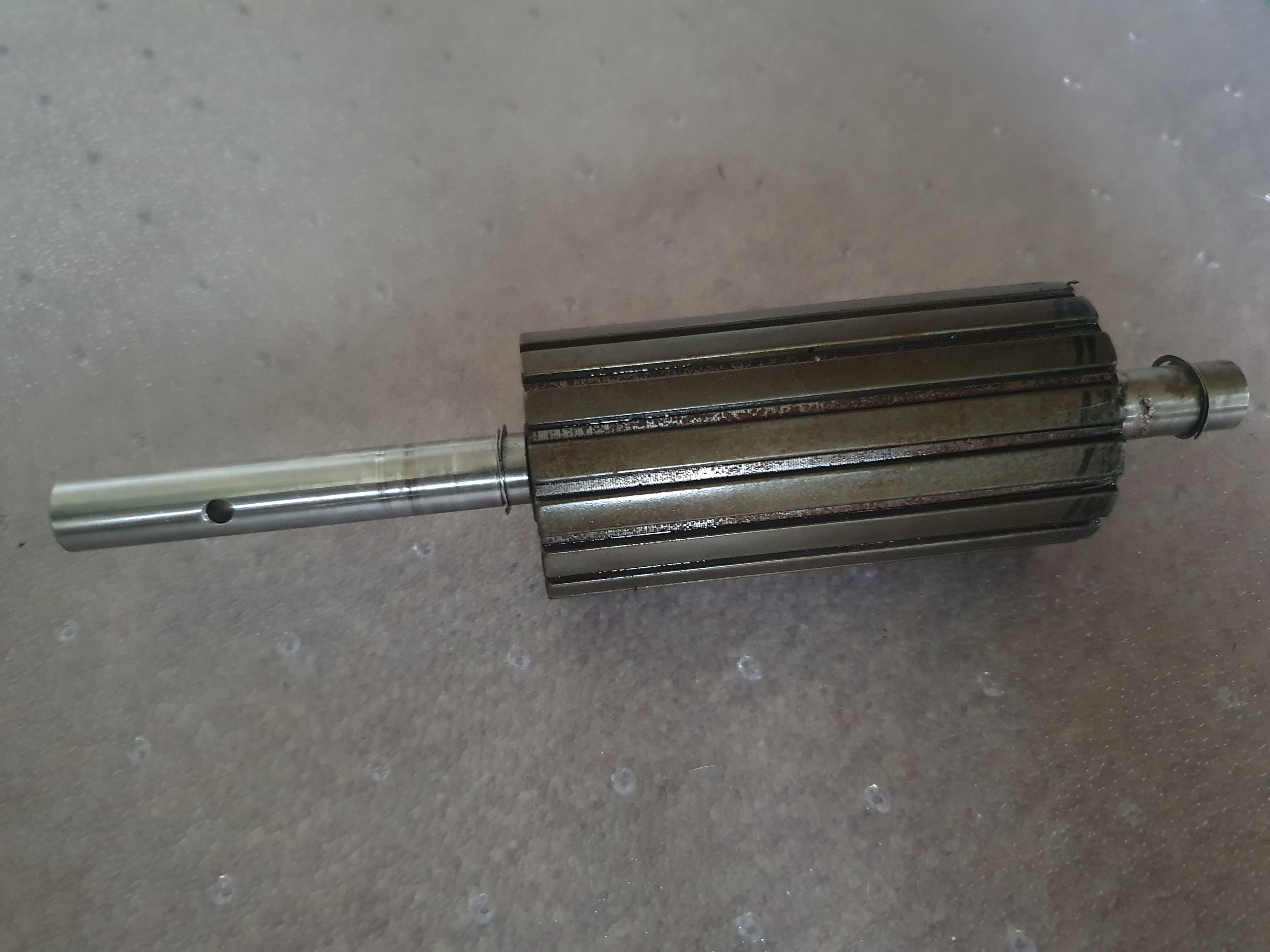
So last week I acquired a Lift mast and motor that had burnt out. It appears that the lower circlip had failed allowing the rotor to push forward into the windings. One of the magnets managed to tear and short out a winding resulting in another winding burning out. I’m not sure if it’s a design flaw, but I have seen a few units with this type of failure now.
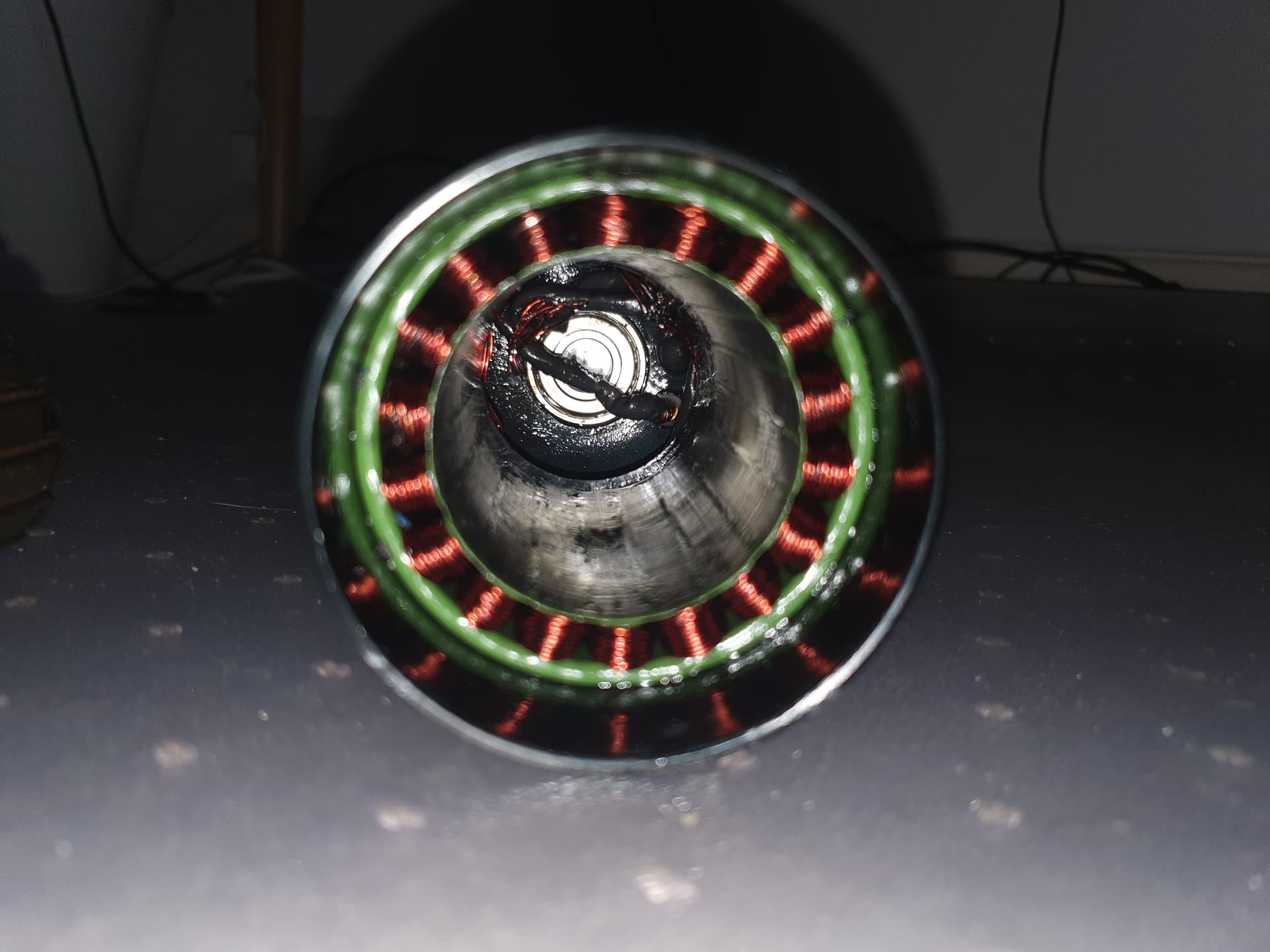
I’m now slowly disassembling the unit (when I have time) and am hoping I may be able to rewind it and get it all back up and running again. Either way it’s going to be interesting to see exactly how the motor is wound.
I found a guy selling on on Facebook so thought why not buy it…
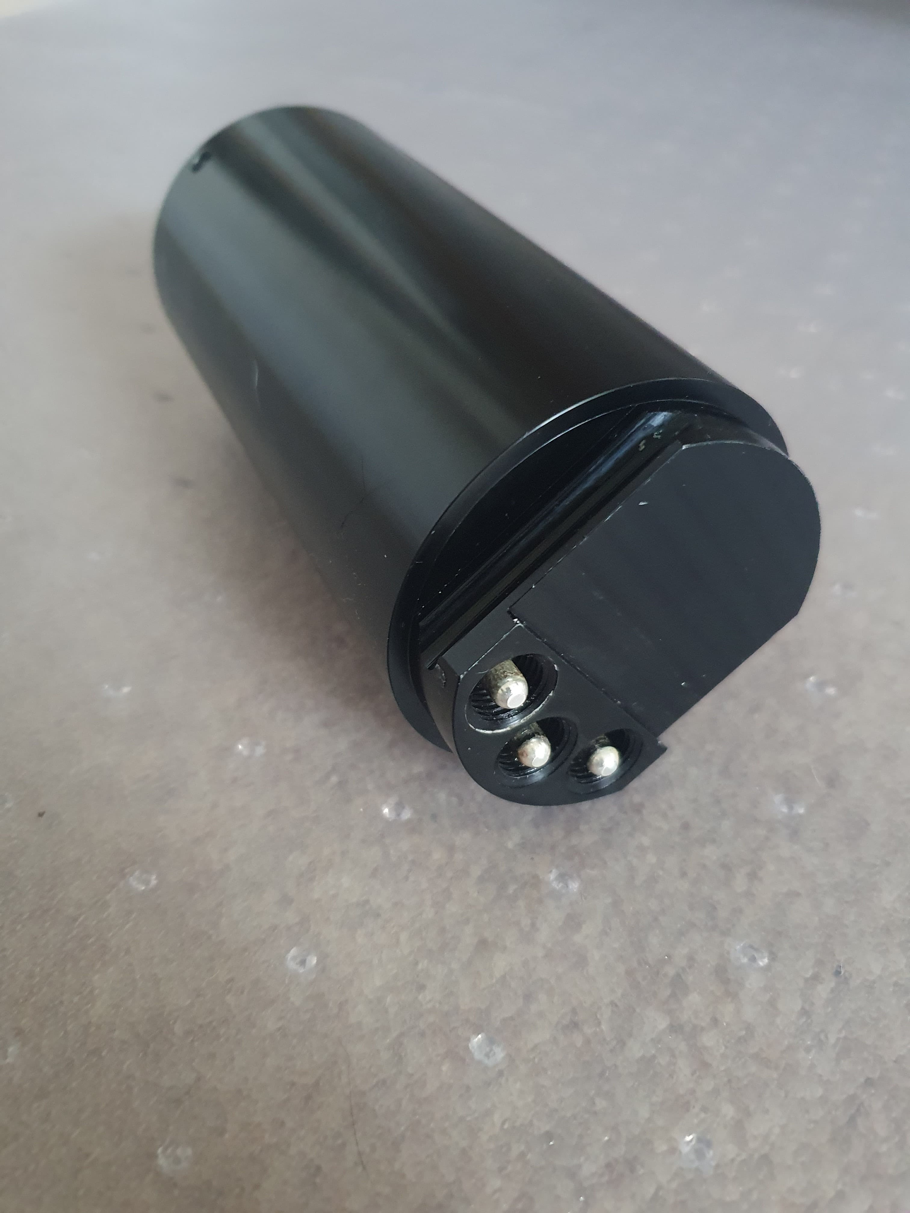
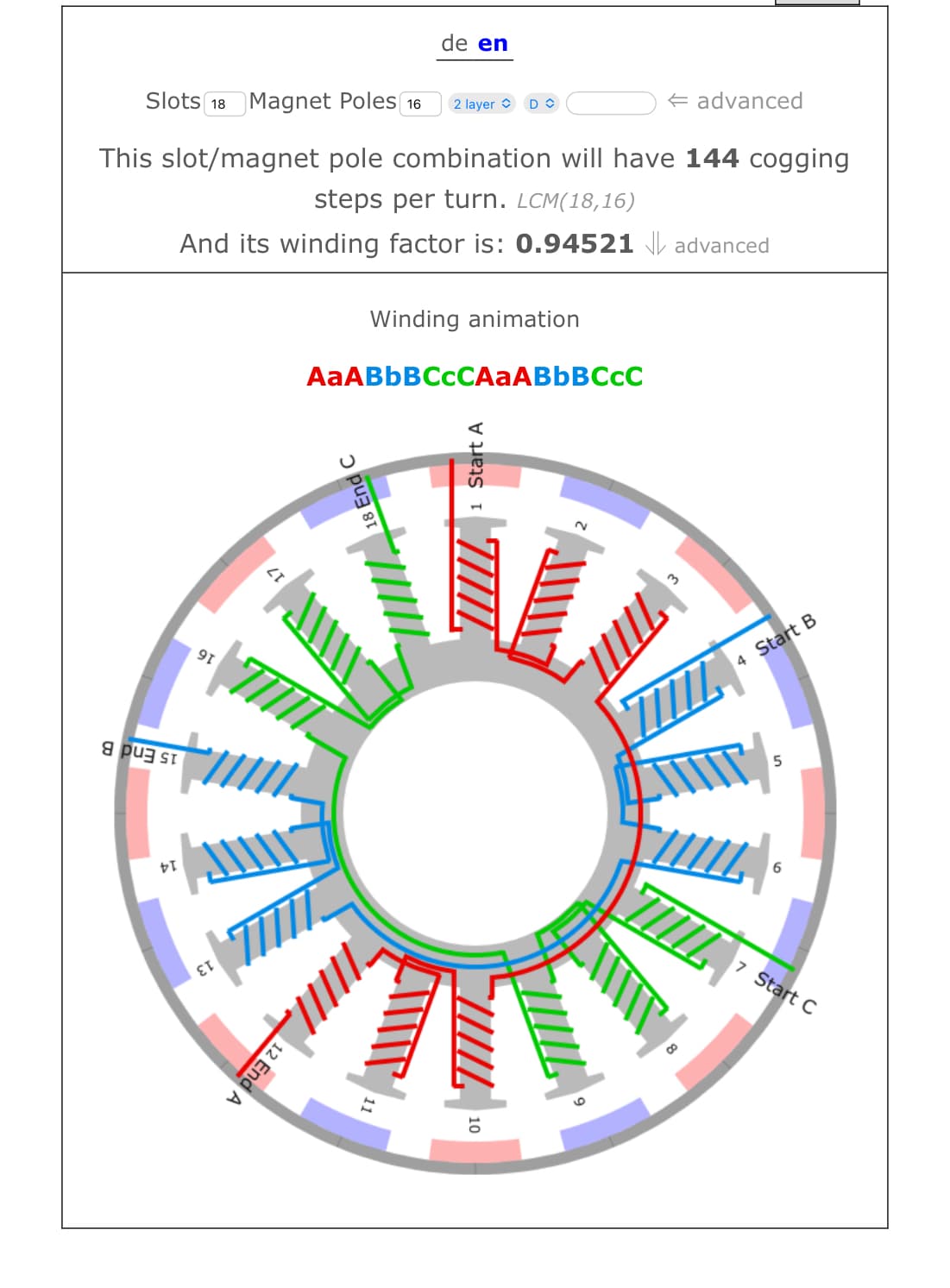
Yes its a 18S16P motor (although this info has been known for a few years already when I posted it about 2-3 years ago). What’s more interesting is how they use connectors on the motor and how the construction is done.
It will be very iteresting to see how revinding will turn out…
I hope you will post some pictures of the process.
Did you ever done somthing like that?
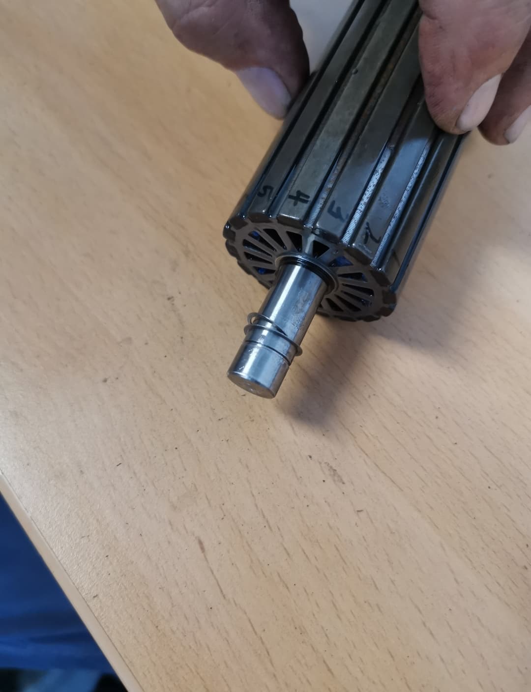
I wondered about axial play of the prop.
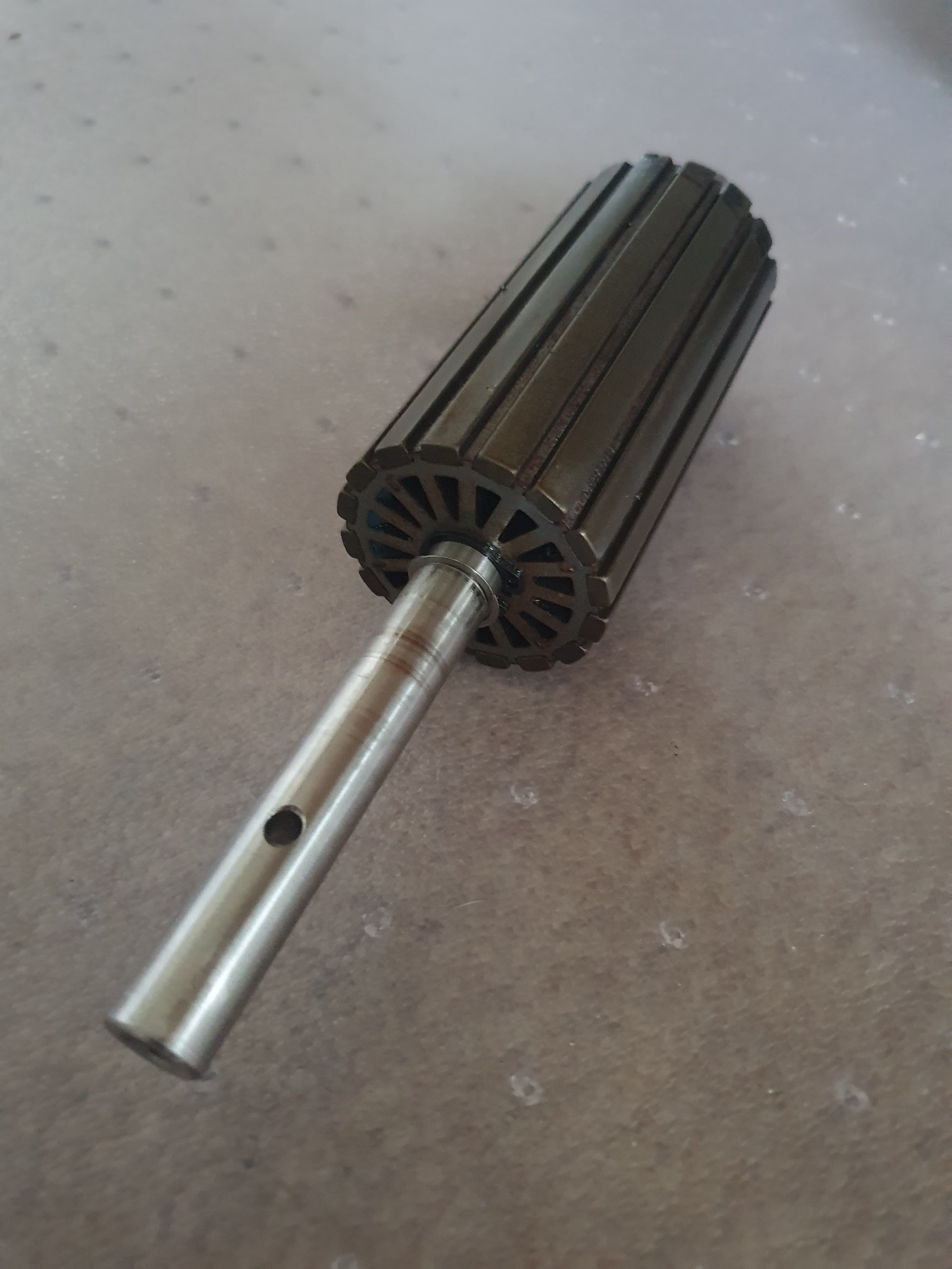
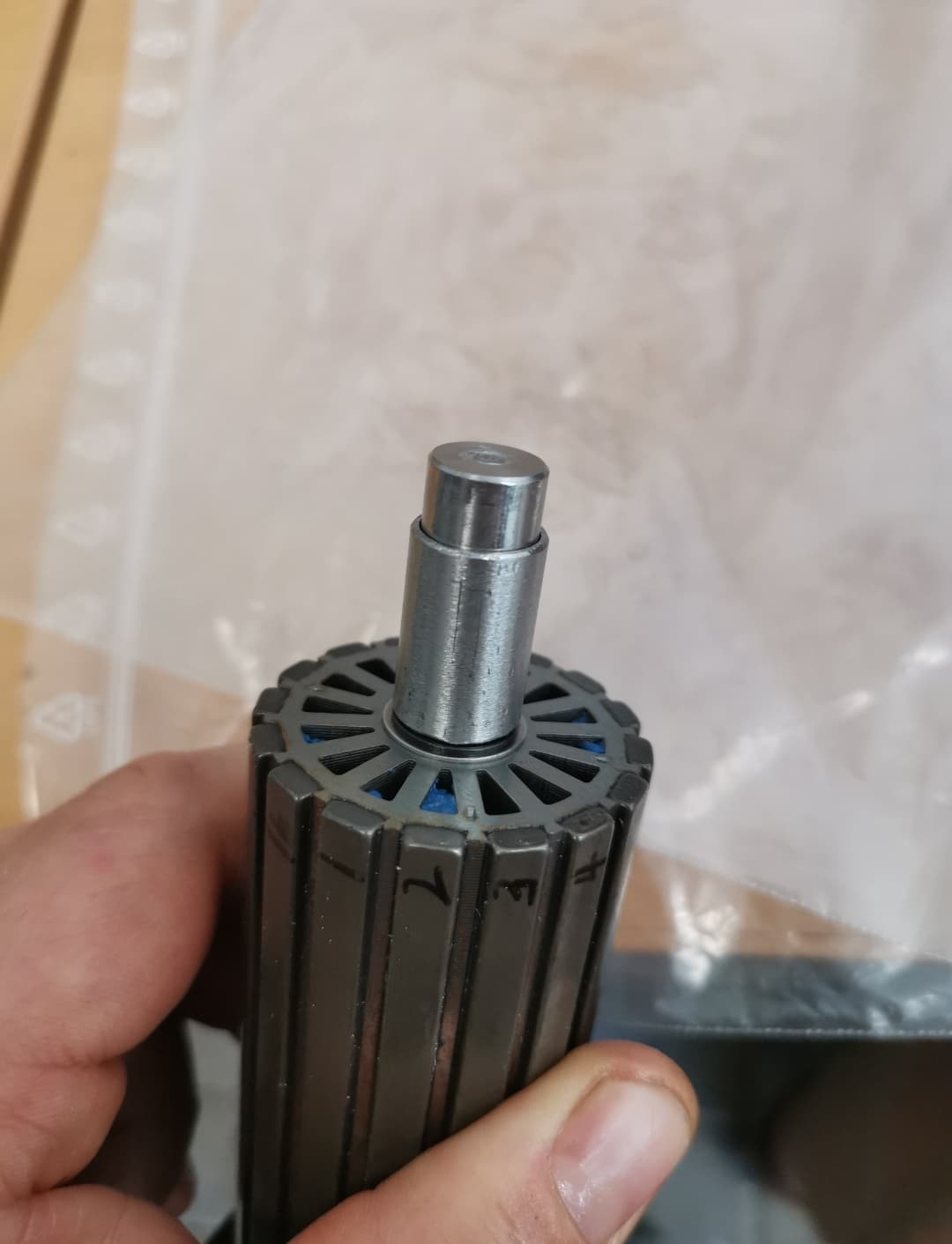
After opening it up i also found the rear circlip out of position.
Got some stainless pipe and now this won’t happen again
Motor casing is 67.76mm diameter. Casing thickness is close to 2mm.
Rotor is ±45mm if I remember correctly.
I’ll get some measurements when I have some free time.
Rotor: 16 Poles with 44mm diameter (including the magnets) x 89mm length
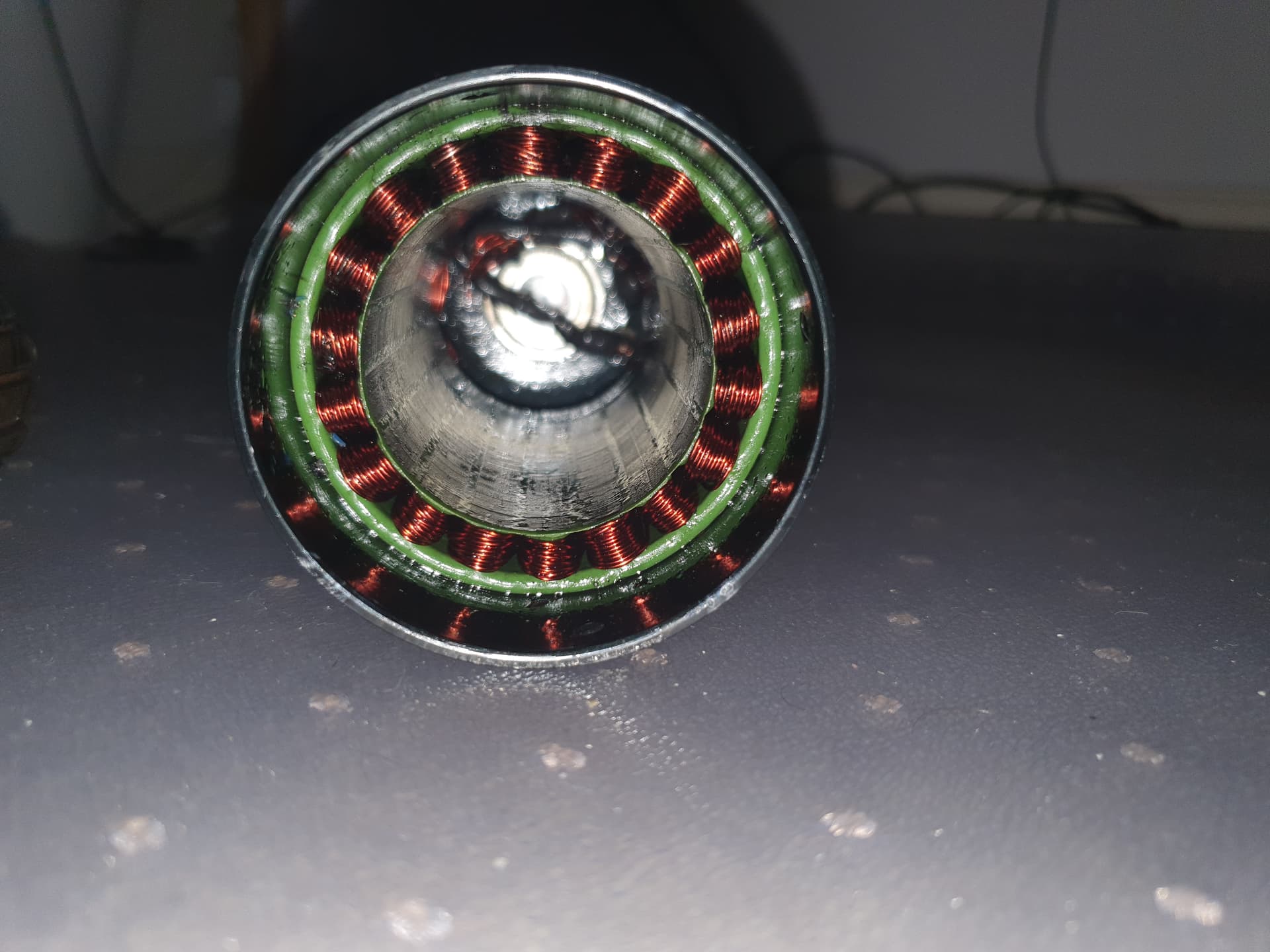
Stator: 18 Slots, 45mm (ID) x 63.5mm (OD) x 89mm length
Outer casing: 67.6 (OD) x ID to match stator x 135mm (without rear end cap and adaptor to fit to mast etc)
I’ve done some outrunner winds but not inrunners, passing the wire through the hole will be a challenge. The stator can probably be removed just by heating and pressing out the laminations when hot, that has worked for me. 200 deg C / 1h
I would try to wind each phase on a dedicated mandrel to keep it neat and pass that or make a needle for threading the wire through.
I’m not too phased about passing the wire through the hole, that I can make a number of tools to do the job.
I think the most challenging part will be removing the stator. I’m going to have to design a puller of sorts that wont damage the stator. The base of the motor unit can’t be removed from what I can see so I need to insert a puller, expand it and then pull the stator back out. Kinda like an internal bearing puller.
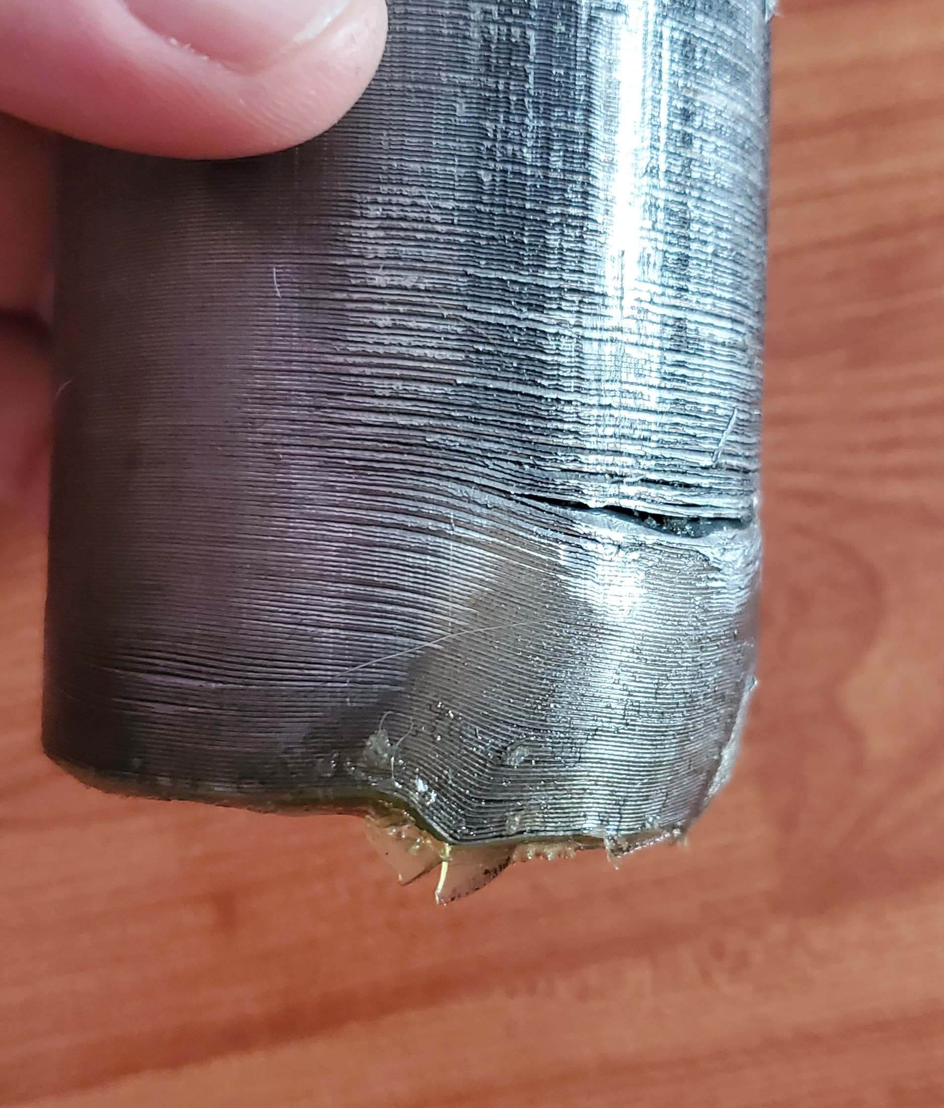
If you haven’t softened the glue enough by heating, it may turn out like this.
By the way, the internal diameter of the 66160 motor housing is 63.5 mm.
Ouch. Then the question is how isolated the lamination sheets are after pushing out with that kind of force. If it doesn’t want to come out, don’t force it!
It’s not like there’s much to lose really. The time it would take to try rewind it in the housing would probably far supersede the value of just buying a new unit, so the way I see it is that I need to get it out to minimise time wastage. If everything fails, then I’ll just put on one of the 65162 motors and run it like that…
Hmm… it needs to be done without thinking of your time as paid wages. It’s time consuming to get it right and the learning also slows you down. You won’t win that time by pressing out the sheets, it will still be an inrunner which inevitably forces you to thread the wires.
Pressing the stator will allow easier threading both ways. If the stator remains inside, then it will be near impossible to thread one way and pull for the return.
The endplate is pressed in, right? That has to come off for you to be able to connect the new wires to the pins. I’d pop FR a question what he thinks is the way to do it.