I just wanted to share some information of what I’ve been doing during this Corona winter. It’s just a first prototype and far from ready. As you will see, there are still many things to test/adjust and a proper GUI is still absent.
First of all, @samisin,@Felixfoiler, @Vincentbraillard have done an excellent job with their remotes, Volt Remote by @Mantafoils is also on its way and that one looks really interesting.
I want to emphasize that when I refer to other remotes, I’m not talking about yours. I have not tried them and have no idea of how they are constructed and how they perform.
The only remotes I can refer to are, my own YAHEF/Hiorth remote, Flipsky VX3, Maytech and a cheap China thumb throttle remote.
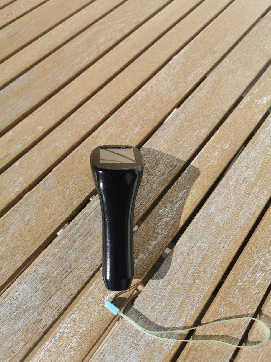
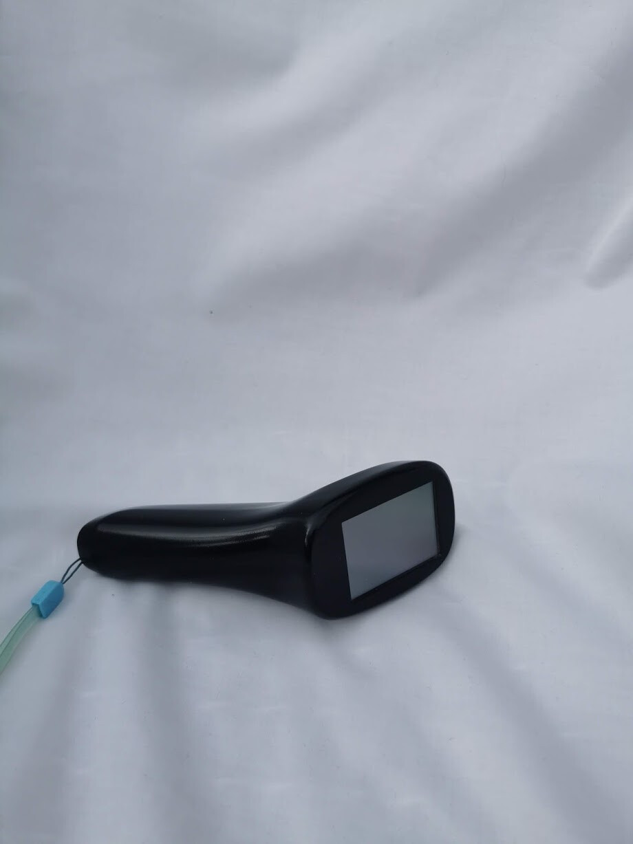
The Flying Remote is totally designed from scratch, both the housing and the electronics. During the winter and spring the remote has transformed from this.

to this
Trigger
Let’s start with the most important thing. I have spent quite some time trying to perfect the trigger. I mean, there is no point in having a remote with a nice display and a lot of fancy features if the trigger doesn’t work. Worst example is the VX3 with a decent display but the trigger is a disaster. It has a travel distance of only 15 mm and just 36 effective steps. It’s more or less an on/off switch with a display telling us whether the motor is on or off.
All remotes I’ve tried so far have a common problem with the trigger, plastic rubbing against plastic causing friction. You can feel the friction in the form of small jumps when the trigger is slowly pressed and released. The friction gets even worse if the trigger is pressed from a side angle. Because of the play in the connection between the trigger and housing, the side of the trigger scratches against the housing, creating even more friction.

So, from a trigger perspective, to get a controlled and smooth ride it comes down to a couple of things. The trigger has to run smooth, have a good resolution, a large rotation angle and a long travel distance.
I have tried to address these things by mounting the trigger on a stainless steel axle. The axle is then connected to the housing through two stainless steel bearings making it running super smooth back and forth. In this way, the friction problem and the side to side play problem gets solved since everything can be mounted really tight, without almost any play at all.
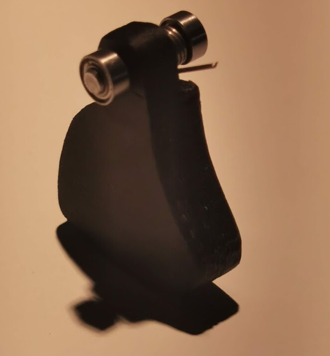
Accuracy of the trigger is also good, about 1000 steps are detected without too much noise and, with the trigger having a rotation angle of 56 degrees and the tip of the trigger has a travel distance of 25mm, it becomes really responsive, smooth and accurate.
Another potential issue is that they are all using an VESC API with the limitation of 126 steps, i.e. roughly 1.3A per step, given that your upper motor amp limit is set to 160A (except the VX3 where the limitation lies in the analog reading). I’m not sure if this actually is an issue, can’t really say I’ve felt the 1.3A jumps with the Maytech remote but in order to utilize all the steps available from the hall sensor, another API with no limitations will be used to feed the VESC.
I have three different springs to test, form soft to hard. My favorite at the moment is the soft one but I’m not sure how it performs in action, it might be too soft. We’ll see, I have to test all of them on the water. At least they don’t corrode. They have along with the bearings and axles hung outside all winter and spring. From time to time, I’ve sprayed them with salt water and there is no sign of corrosion.
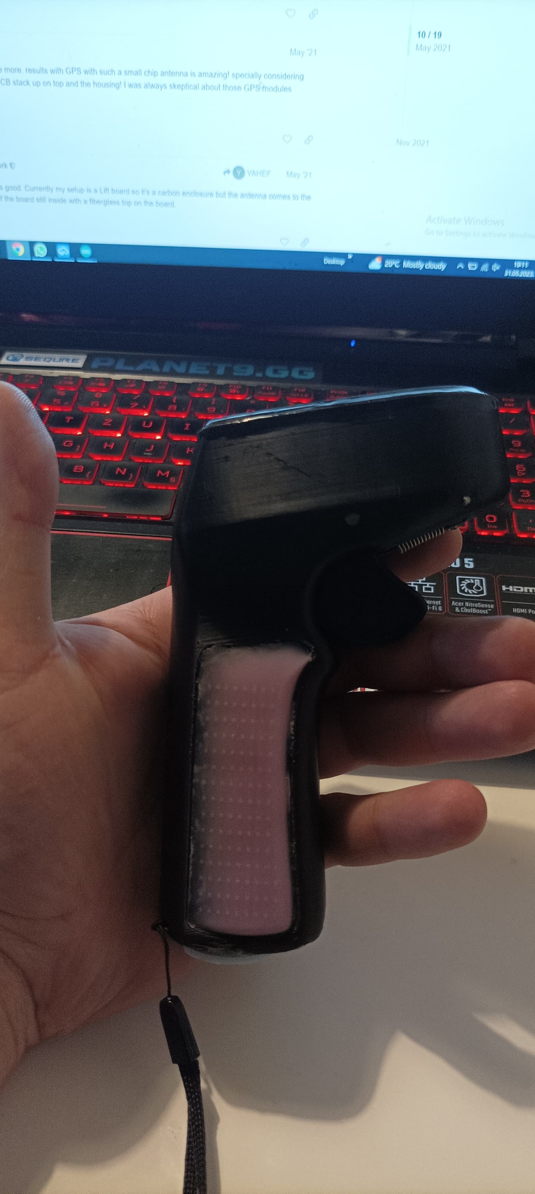
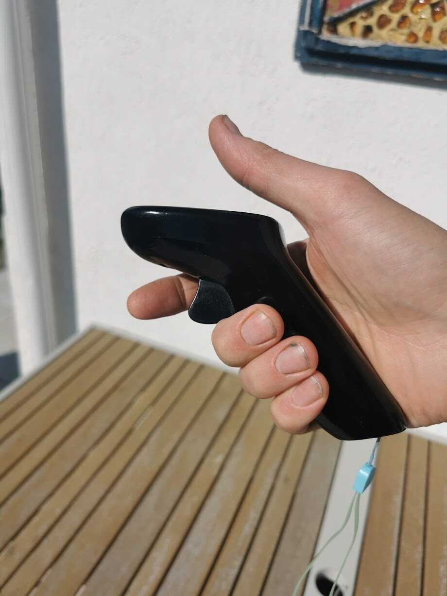
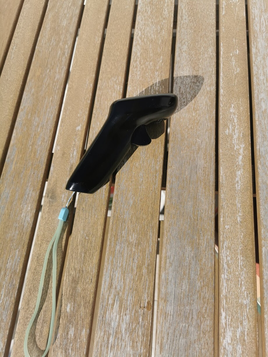
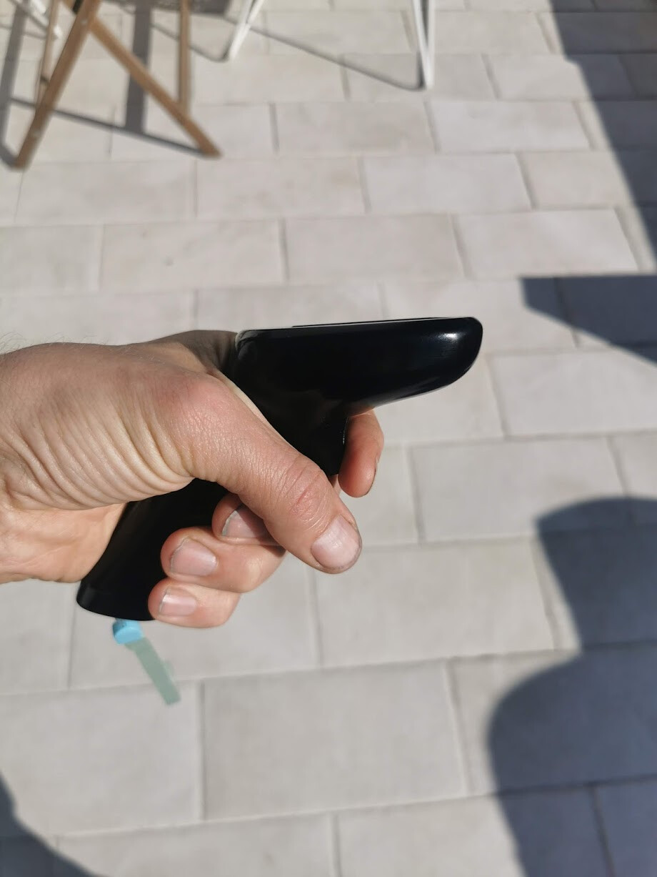
Handle
Almost just as important as the trigger is a comfortable handle. I know this is quite individual because of different hand-sizes but again, worst in class is the VX3. That one is too short for my big hands and it feels like it will slide out of my hand making me squeeze it harder and harder. Also, my YAHEF/Hiorth remote is not very comfortable to hold as that handle is too short as well and also too wide.
I’ve tried to make the handle fit as many different hand-sizes as possible. In endless iterations I’ve printed different versions and tried them out on friends and family and finally ended up with this design.
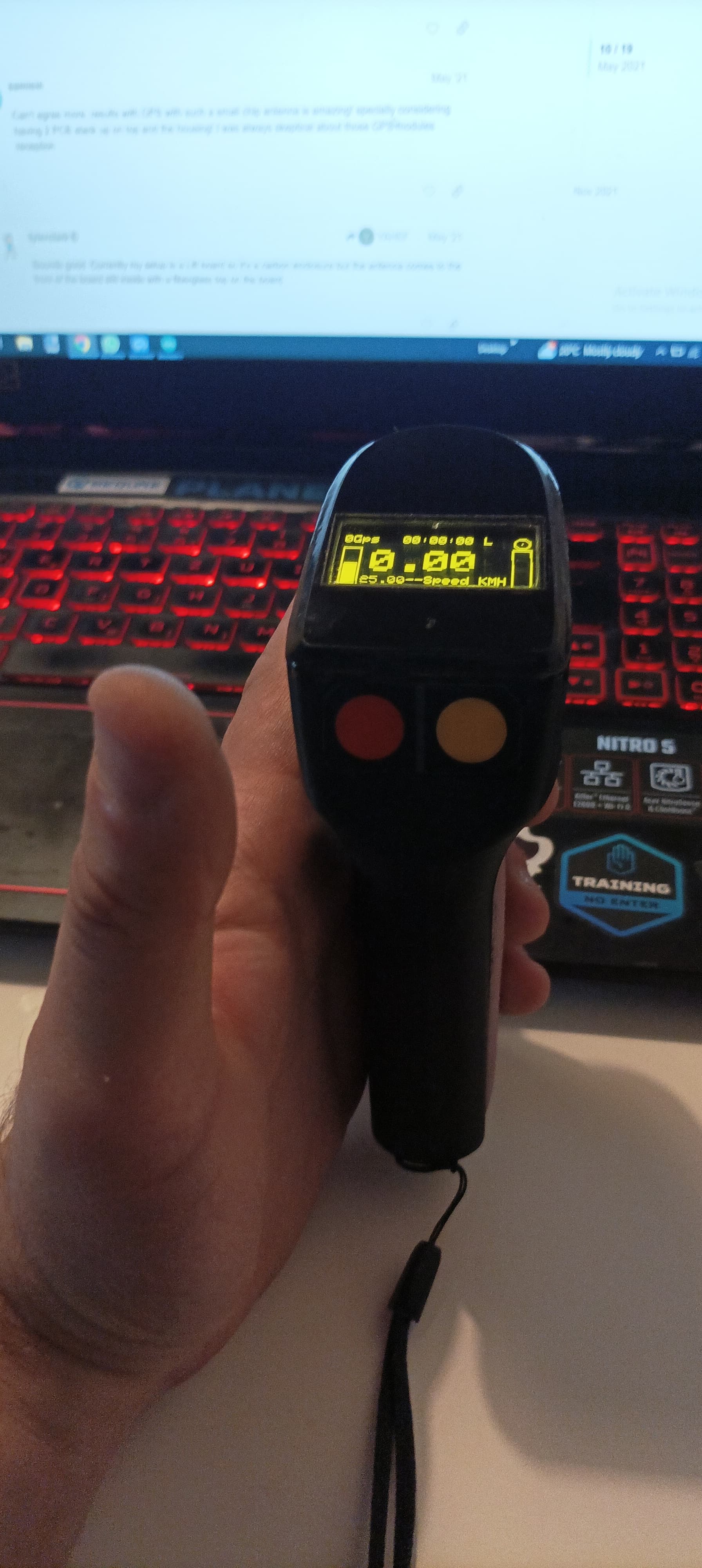
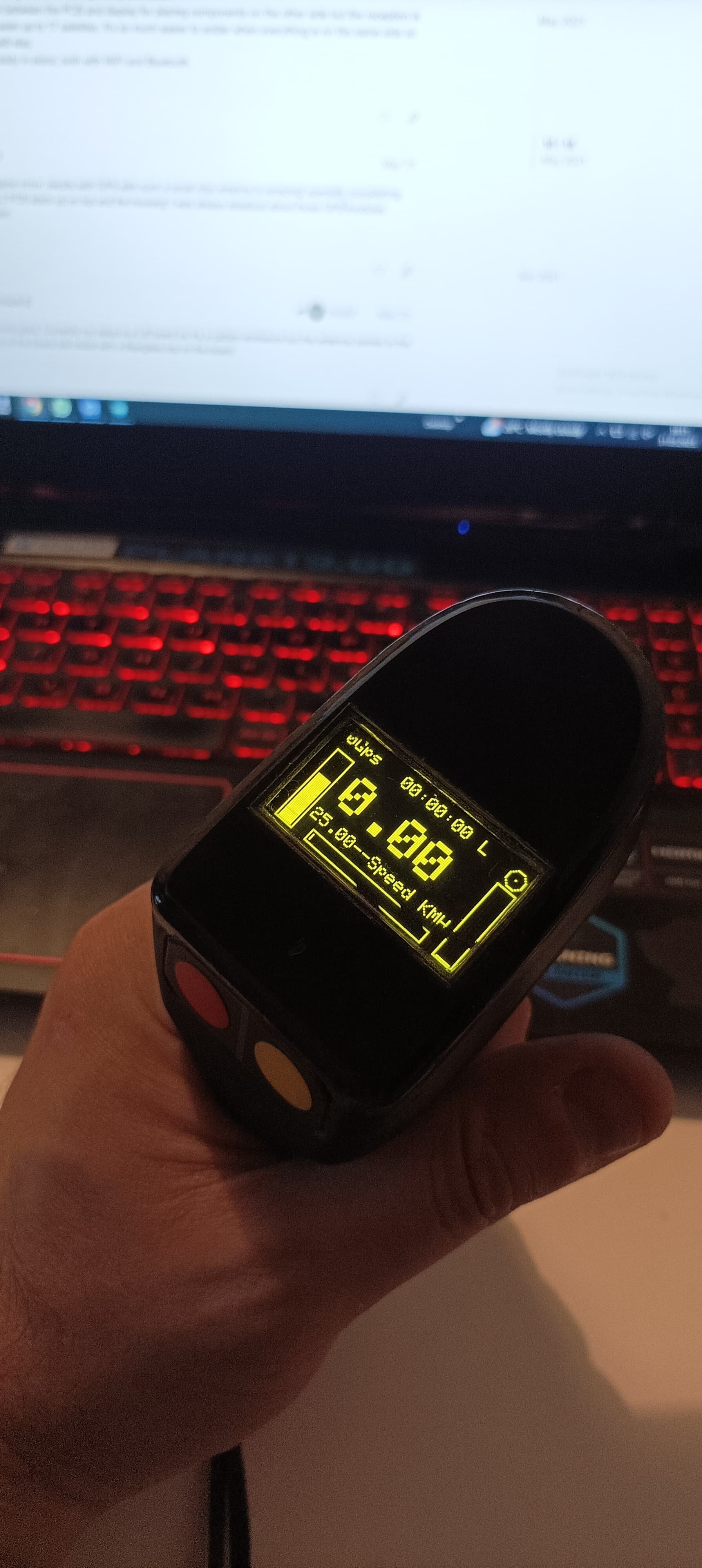
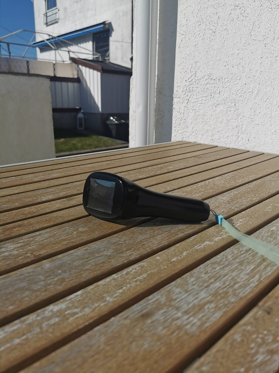
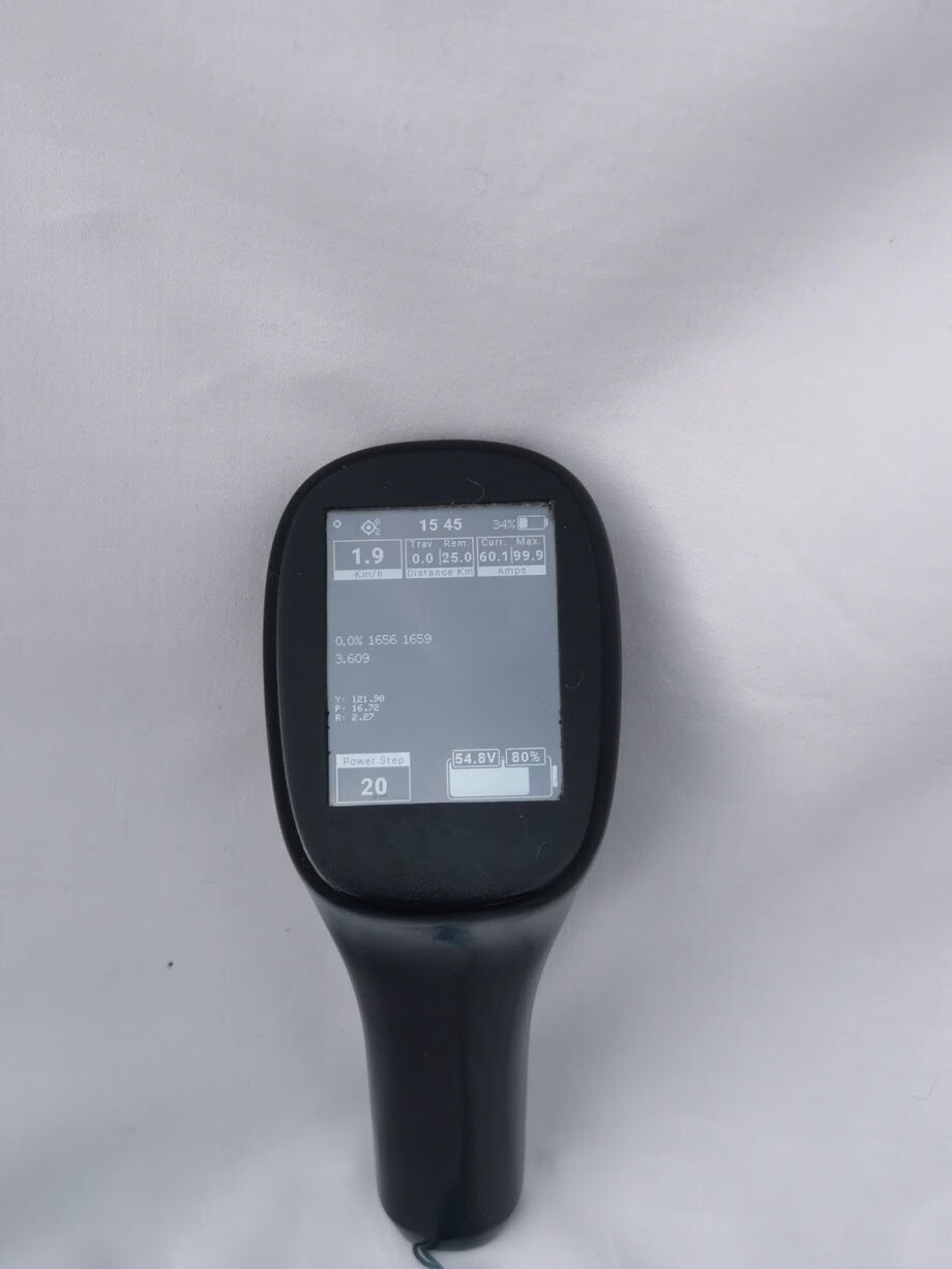
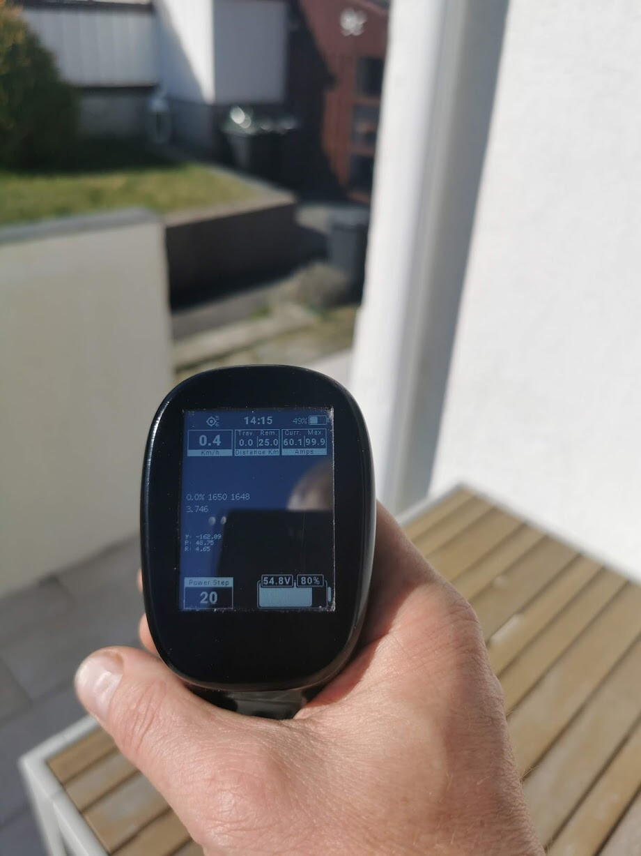
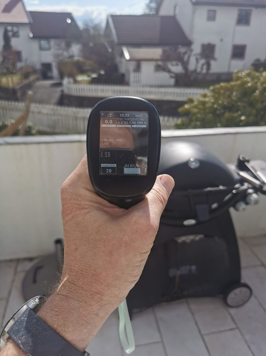
Display
As you might have seen in the images, there are no buttons on the remote, but actually there are. In theory there are 76800 of them. It’s a 2.4 inch, resistive touch display. It’s transmissive and delivers almost 1200 cd/m2 making it sunlight readable.
I have to admit, a transflective display is a bit better when the screen is angled directly to the sun, but in all other situations this transmissive display is superior because of the bright back light.
For example, when it’s sunny and bright and the display is not directed directly to the sun, most cheap transflective displays (including the VX3) don’t have enough backlight to make the screen fully visible.
The display has a 8 bit parallel interface which means the refresh rate is much faster compared to a serial (SPI) interface.
Since no physical buttons are needed the overall size of the remote can be kept relatively small even with a relatively large display. I’ve managed to tune the touch screen to only accept finger-like touches, pointy objects will not cause an input.
Radio
At the moment, I’m using Bluetooth Classic but I’m not 100% happy with the performance. It’s much better than Maytech and VX3 but I will try to implement LR (low rate/long range) WiFi and/or play around with some different antennas.
If I’m still not satisfied, I might consider adding a LoRa chip or similar.
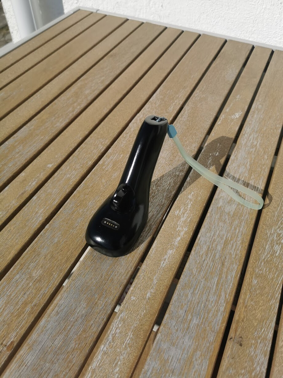
Charging
I have chosen to have a proprietary cable. I will consider having wireless charging later but at the moment I need an external connector for debugging and resetting the remote if it goes into an endless loop (some bugs in the ESP32 bluetooth stack but I think they are fixed now).
Charging is done at 1A with temperature control of the battery.
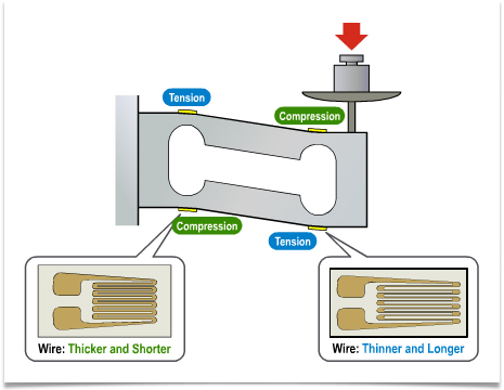
IMU (Gyro + Accelerometer + Compass)
I have managed to get the sensor’s digital motion processing (DMP) to work. DMP is a kind of a small cpu that you can load a program into. The sensor then offloads computation of motion processing algorithms from the host processor by doing it internally, like quaternion calculation, gyroscope calibration and so on. I’m not sure how Invensense/TDK does it but it’s so much more accurate than doing motion processing yourself.
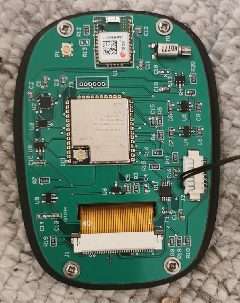
PCB
All components, except the battery is soldered to the PCB.
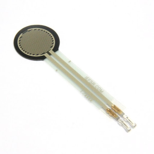
GPS, IMU, charger, vibration motor and hall sensor.
Other
Of course it’s waterproof. Have had a mock-up laying in water for a week without water penetration.
Estimated 20 hours of logging space.
OTA (wireless) firmware updates.
Samsung INR18650 35E battery.
10 - 12 hours operating time.
It Floats
Weighs 160g.
Receiver
The PCB for the receiver is about to be sent for manufacturing. The receiver will only be compatible with VESC. Apart from the ESP32, there is also an IMU in order to measure the angle of the board. The IMU will be used to cut the power to the motor if the board tilts over a certain angle or abruptly gets a negative acceleration, i.e. crashing into something.
Firmware
Until now, the hardware has been my first priority and making sure all the sensors are working but I have a long list of features I want to implement. The first priority is to get the most basic functionality in place in order to test the remote on the water and see what it feels like.
One feature quite high up on the list is the cruise control. I don’t like how the cruise control is implemented on the VX3 and Maytech. It doesn’t feel natural to completely release the trigger and then, when you fall, have to press the trigger or break and release it again to cancel the cruise control and stop the motor. That is kind of the opposite of how you normally do when you fall.
Instead there will be perhaps 25 power steps, not sure of how many yet, maybe configurable. The trigger has to be pressed all the way in and held there. To change power step, touch the screen at the lower left corner and either press +/- on the screen or tilt the remote to the right or to the left in order to adjust the power. When you’re about to fall, just release the trigger in the normal way.
We all have different needs and perspectives on how and what data we want to present on the display. Someone just wants the main battery, while others want to see a lot more. So I’ve got this vision of being able to dynamically build your own views from a set of items, much like on your smartphone homescreen, we’ll see.
Then comes the big question. Will this ever be available? The short answer is. I’m not sure. There are so many uncertainties around how to manufacture the handle in a cost efficient way and without too much initial costs. Also there are some good products coming to the market quite soon and I’m perhaps 6-12 months behind and the market is not that big yet.
Anyhow, what do you think? Is the efoil community ready for a ‘smartphone with a trigger’? Have I gone mad?
 .
.
 Do you have any estimate when to start selling those remotes? At least I have to evaluate if it makes sense to wait or buy a cheap and crappy one for the meantime.